Trotec VX 5 User manual

OPERATING MANUAL
DRYING UNIT
VX 5
EN
TRT-BA-VX5-2.0-HS-002-EN

B - 1Operating manual drying unit VX 5 EN
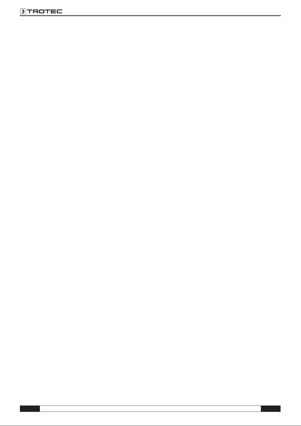
Fig. 4
Fig. 3
Fig. 1
1 silencer
NR 19
2 drying
unit VX 5
3 HEPA filter
HC
4 water separator
WA 4i with micro filter
system
5 drying unit
DA 4
Fig. 2
Table of contents
Safety .......................B - 1
Scope of delivery ..............B - 1
Device description .............B - 1
Start-up .....................B - 2
Shutdown ....................B - 2
Care and maintenance ..........B - 2
Warning .....................B - 2
Troubleshooting ...............B - 3
Technical data.................B - 3
Declaration of conformity ........B - 4
This release replaces all previous releases. No part of this publication may
be reproduced without written permission. The same applies for elec-
tronically processing, duplicating or spreading the publication. Subject to
technical changes. All rights reserved. Trademarks are used without guar-
antee that they may be used freely and primarily following the spelling of
the manufacturer. The product names used are registered and should be
treated appropriately. The right to make construction changes in the in-
terests of constant product improvement as well as changes to the shape
and colour is reserved. Scope of delivery may vary from product images.
This document was produced with all due care. We accept no liability
whatsoever for mistakes or omissions. © TROTEC®
Safety
Read this manual carefully before starting or us-
ing the device. Store the manual near the device
or its site of use!
Observe the following instructions:
• Do not use the device in potentially explosive
rooms.
• Do not use the device in atmospheres contain-
ing oil, sulphur, chlorine or salt.
• Set the device up in an upright and stable po-
sition.
• The device is designed for indoor use. Do not
use the device at a humidity level of more than
90% or in the rain.
• Ensure that the air inlet and outlet are not ob-
structed.
• Ensure that the suction side is kept free of dirt
and loose objects.
• Do not cover or transport the device during
operation.
• When using cable drums, always unroll the
cable completely.
m During damage restoration, provide a
sufficient fresh air supply! The room tem-
perature must not exceed 35°C. Ventilate
several times a day. If necessary, direct
the exhaust air produced by the VX out of
the room. You can also set up the VX in
another room (not outdoors!) and direct
the air current needed for drying to the
inside.
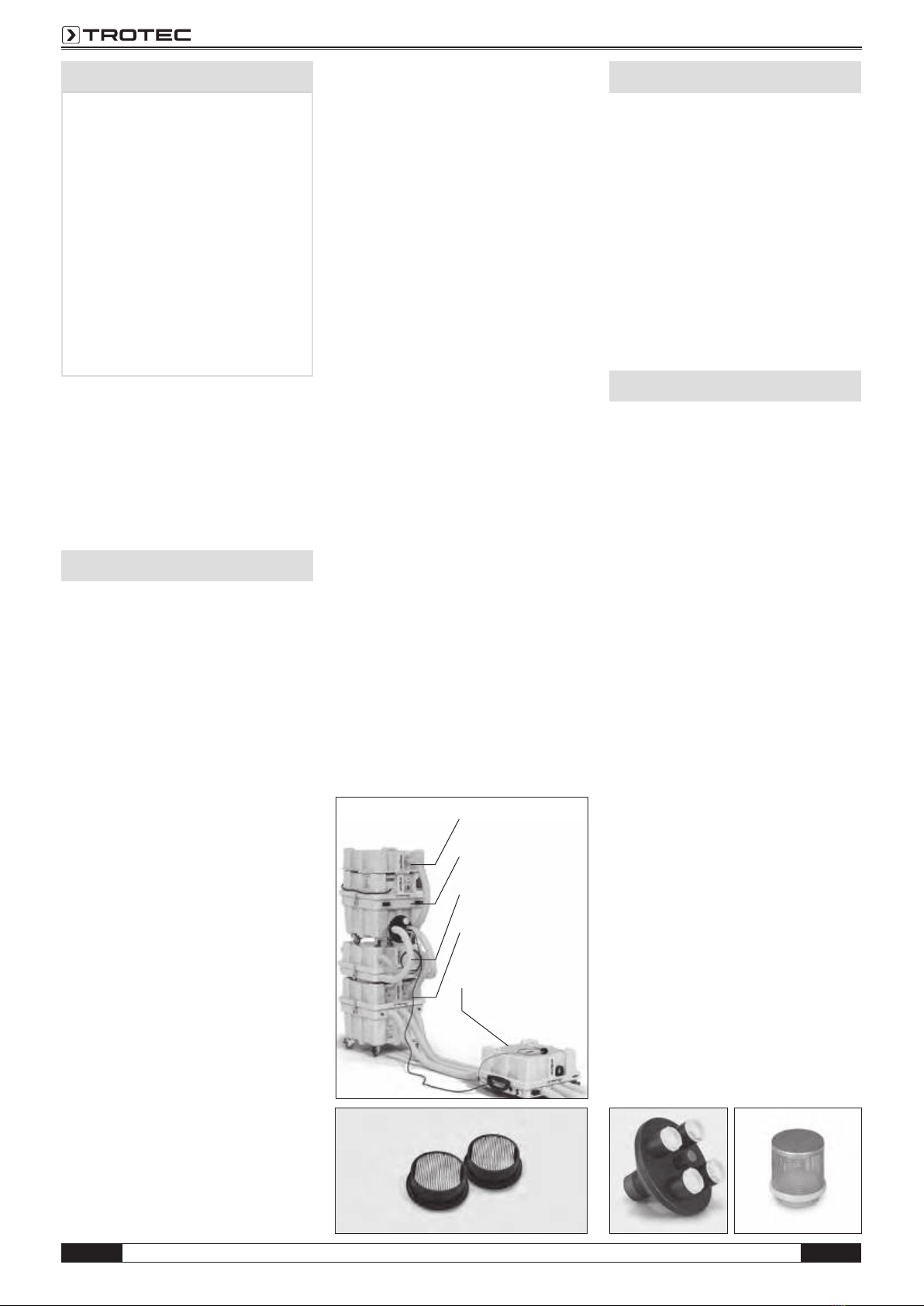
• Make sure to keep the dust exposure as low
as possible in low pressure operation by using
suitable micro filters (fig. 2).
• Make sure that the suction strainer (fig. 4) is
used when the device is operated with excess
pressure.
• Repair and maintenance work on electrical
equipment may only be carried out by an elec-
trically skilled person.
• On construction sites, the compressors must
only be operated with an upstream residual
current device (RCD) 30mA.
• Do not operate the device in a heavily
dust-loaded environment (e.g. during grinding
work).
Intended use
The turbines are to be used in low and excess
pressure mode for insulation drying of floating
screeds, flat roofs (warm roof constructions) and
hollow floorings. They are intended to transport
non-aggressive and non-explosive gaseous me-
dia. Any other use is regarded as non-intended
use.
Improper use
The devices are not suitable for the inflation of
bouncy castles or similar objects. Media other
than those listed as intended use must not be
transported.
Personnel qualifications
The compressors may only be operated by ex-
pert persons who have been instructed in the
operation of the devices and trained in insulation
drying techniques. The operating manual is to be
consulted for this purpose. Instructed persons
have been informed of and, if necessary, trained
for the tasks they were entrusted with as well as
of potential hazards resulting from inappropriate
behaviour.
Scope of delivery
Standard scope of delivery:
• 1 x compressor
• 1 x suction strainer fig. 4
• 2 x connectors 50/38 mm
• 1 x operating manual
Optionally available accessories:
• door gap nozzle PlanoPro
(Art. no. 6.100.000.160)
• MultiQube silencer NR 19
(fig. 1; no. 1);
Art. no. 6.100.000.120
• Quad distributor Pro (fig.3);
Art. no. 6.100.000.142
Description of the device
The compressors of the VX series are used for
drying insulation layers. In case of excess pres-
sure drying, the roomair is blown into the humid
insulation layer via bore holes, the insulation
layer absorbs the humidity and returns it to the
environment via the expansion joints.
In case of low pressure drying, a drying chain
(fig. 1) consisting of water separator, air filter
and compressor is used to suck the air out of the
insulation layer. The air sucked out of the bore
holes is separated from solid particles and water
drops inside the water separator. Particles and
mould spores are filtered out by the HEPA and
F7 filters.
Should there be any concerns relating to air pol-
lution due to fibres or spores from inside the in-
sulation layer (GefStoffV: Ordinance on Hazardous
Substances), the use of the low pressure proce-
dure is compulsory in order to filter the polluted
air. The silencer allows to effectively decrease the
volume in occupied buildings.
The humid air has to be dried additionally by ade-
quately powerful mobile dehumidifiers.
• To be able to use the high performance of the
VX compressors, it is necessary to operate the
optional quad distributor Pro (fig. 3) with at
least two 38mm hoses. If no quad distributor
can be used, the hose diameter should be at
least 50mm, for otherwise there might be per-
formance losses of up to 10%.
• This VX distributor is equipped with self-regu-
latory step switches.
• The device comes with 4 power stages:
stage 1 with 100 m³/h; stage 2 with 150 m³/h
and stage 3 with 180 m³/h as well as the boost
stage with up to 245 m³/h. In addition, there
is a "whisper mode" with 100 m³/h as well.
For each of these steps, the VX tries to achieve
the target air volume, regardless of the con-
struction.

Operating manual drying unit VX 5 B - 2
EN
Aindication of the selected power stage
Bindication of the motor power
Cplug socket for connection
to a DA 4 or a DA 4 M
Dindication of the air volume flow
E-decrease power stage
F+increase power stage
Gibutton for indication of operating
hours and power consumption
Hwhisper mode
Ipower button
A
B
C
D
E
F
G
H
I
1 power cable
2 LC display
3 communication port
4 power button
5 touchscreen control panel
6 service power socket
7 cooling air filter
8 air exhaust connection
9 air intake connection
9 8
1
2
3 5 6 7
4
mThe turbines are suited for transporting
clean air only. If the transported medium
contains solid particles or other impuri-
ties, it is necessary to install suitable fil-
ters on the suction side (e.g. water sep-
arators, micro filters). If impurities enter
into the turbine, this might damage the
turbine.
mDuring damage restoration, provide a suf-
ficient fresh air supply! Ideally, the room
temperature should not exceed 35 °C.
Ventilate several times a day. If neces-
sary, direct the exhaust air produced by
the VX out of the room. You can also set
up the VX in another room (not outdoors!)
and direct the air current needed for dry-
ing to the inside.
• The compressor is equipped with a multi-
functional LC display. Besides giving informa-
tion on the work stage, air flow rate etc., its
background colour changes. Making use of
the traffic light system, it indicates how suit-
able your drying installation is. An optimal air
flow rate is indicated by a green background
colour when the compressor is running. If the
display is illuminated in yellow, this means that
the installation is OK but the flow conditions for
the dry air are not optimal. Drying can be car-
ried out without any difficulties while the dis-
play is yellow. A red background indicates an
uneconomic operation. The compressor should
not be permanently operated in this condition.
Start-up
• Install the compressor according to the select-
ed procedure.
• Use suitable hoses (observe number and di-
ameter) to set up the drying installation.
• Remove any sealing plugs on the intake or ex-
haust connection!
• Use a water separator for the vacuum proce-
dure! In this case, connect the mains plug of
the VX5 compressor to the socket of the water
separator. This way, the water separator can
switch off the compressor if the amount of wa-
ter is too high. This leaves the water separator
enough time to pump off the accumulated wa-
ter. Once the water tank of the water separator
is empty, the compressor switches back on
and operates in the previously chosen setting.
• For drying operations, only use cables and
sockets complying with the regulations. In ad-
dition to the 16A fuse, the socket should also
be secured by a 30mA residual current device
(RCD).
• Use the power button
to switch the compressor on. The following
working stages are available:
- 3 power stages 1-3
- stage 4: boost stage
- whisper mode
• If an upstream MultiQube DA has been con-
nected, all three valves should be opened.
• Check its structure via the LCD monitor.
- green: optimal air volume flow
- yellow: limit range
- red: air flow rate too low -
installation must be optimized
• In boost mode, the motor runs at its maximum
performance.
• In whisper mode, the compressor runs with a
max. motor power of 60%, thus reducing the
noise emission at night. The night mode is au-
tomatically left after 10h and the compressor
starts to run at its previously chosen power
stage again. Selecting another stage via the
touchscreen will also stop the night mode.
• The communication port is used for
data transfer to the DA4 control unit.
The data can then be forwarded
(USB and modem or USB only).

B - 3Operating manual drying unit VX 5 EN
• Pressing iwhile the device is switched on al-
lows you to see the number of operating hours
and the energy consumption.
Shutdown
• Use the power button
to switch the compressor off.
• Wait until the motor has come to a standstill.
• Reinsert the sealing plugs removed during
start-up.
Care and maintenance
• Always remove the mains plug from the mains
socket first.
• Check the cooling air filter and exchange after
around 6 months or if required.
• Regularly check cables and
plugs. Damaged cables and plugs must be re-
placed.
• Maintenance and repair work should only be
carried out by Trotec.
m Suction side: The compressors of the
VX series have a strong suction air flow.
Small objects and particles can be sucked
in and lead to injuries. Pay attention that
no person is standing near the inlet or
outlet opening while the compressor is
running. If there is no tube or hose con-
nection assembled on the suction side,
the air inlet grid (fig.4) must be installed.
mBlow-out side: The compressors of the
VX series have a strong outlet air flow.
Sucked-in objects and particles may be
ejected at a high speed and lead to in-
juries. Therefore never hold your hand to
the outlet opening.
Attention: The outgoing air may reach
60–70°C.
Troubleshooting
Little or no air is sucked in or blown out:
• Check the installation and, if necessary, add
relief openings to improve the air circulation
and to operate the compressor within its op-
erating range.
Motor is not running:
• Check whether voltage is applied.
• Check the electrical connections and safety
installations.
• Check whether the thermal protection has
been activated.
Motor switches off during operation:
The compressor has been overheated due to im-
proper operation and switched off by the thermal
protection. This could be due to the following
causes:
• High counter pressure on the blow-out side
has led to overheating.
• Too strong flow resistance on the suction side
has led to overheating in suction mode.
• Wait until the motor has cooled down, switch
off the device and switch it on again.
• Check the installation and add relief openings
to improve the air circulation and to operate
the compressor within its operating range.
• Check whether the two cooling air filters are
soiled or clogged.
m Permanent or repeated overheating may
destroy the motor electronics. Avoid over-
heating the device and provide a suffi-
cient air circulation (see also "Safety"
and "Start-up"). If necessary, direct the
warm air out of the room. Room tempera-
tures above 35°C are to be avoided dur-
ing operation.
Technical data
Excess pressure /
low pressure...........270 / 220 mbar
Air flow rate max. ............250 m³/h
Motor voltage ........ 1 ~ 230 V / 50 Hz
Motor power/motor current. 1.2 kW / 5.5 A
Main fuse ..................... 16 A
Important information on recycling!
In the European Union, electronic
equipment must not be treated as do-
mestic waste, but must be disposed of
professionally in accordance with Di-
rective 2002/96/EC of the European Parliament
and Council of 27th January 2003 concerning old
electrical and electronic equipment. At the end of
its life, please dispose of this device in a manner
appropriate to the relevant legal requirements.

Operating manual drying unit VX 5 B - 4
EN
TROTEC®GmbH & Co. KG
Grebbener Straße 7 • D-52525 Heinsberg • Tel.: +49 24 52962-400 • Fax: +49 2452962-200 • E-mail: [email protected] • www.trotec.de
Managing Director: Detlef von der Lieck
• Amtsgericht Aachen HRA 5232(Commercial Register, Section A, no. 5232 at the Local Court Aachen)
The manufacturer: TROTEC®GmbH & Co. KG
Grebbener Straße 7
D-52525 Heinsberg
herewith declares that the compressors have been produced in accordance with the CE
guidelines on mechanical engineering as indicated in the following standards.
Important note:
In case of improper use, installation, maintenance etc. or unauthorized changes of the fac-
tory-supplied device version, this declaration loses its legal validity.
Device version: Compressor
Series: VX 5 2.0
Applicable regulations: EC Machinery Directive (2006/42/EC)
EC Directive about electromagnetic compatibility (2004/108/EC)
Applied national
standards and technical
specifications: EN 60204-1, VDE 0113-1:2009-10,
EN 55011:2011
Declaration of conformity
EC Declaration of Conformity
(Translation of the original)
Heinsberg, 11 November 2014
Managing Director: Detlef von der Lieck

B - 5Operating manual drying unit VX 5 EN

Operating manual drying unit VX 5 B - 6
EN

Trotec GmbH & Co. KG
Grebbener Str. 7
52525 Heinsberg
+49 2452 962-400
+49 2452 962-200
info@trotec.com
www.trotec.com
Table of contents
Other Trotec Industrial Equipment manuals

Trotec
Trotec SpeedMarker 1350 User manual

Trotec
Trotec Airozon 5000 User manual

Trotec
Trotec SpeedMarker 1600 User manual

Trotec
Trotec SpeedMarker 1300 User manual

Trotec
Trotec VSC206 User manual

Trotec
Trotec Atmos Pure User manual

Trotec
Trotec DH 25 S User manual

Trotec
Trotec FS 200 User manual

Trotec
Trotec SpeedMarker 50 fiber User manual

Trotec
Trotec DH 105 S User manual
Popular Industrial Equipment manuals by other brands

Afag
Afag aflex 150 qc Operating or assembly instructions

Scheppach
Scheppach HW2500 Translation of original instruction manual

Festo
Festo CPX-AB-1-7/8-DN Assembly instructions

Bosch
Bosch Rexroth TS 2plus WI 2/X Assembly instructions

Electron
Electron E-ROBOT+3 Series user manual

Festo
Festo SPC11 Series Supplementary Description