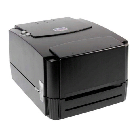
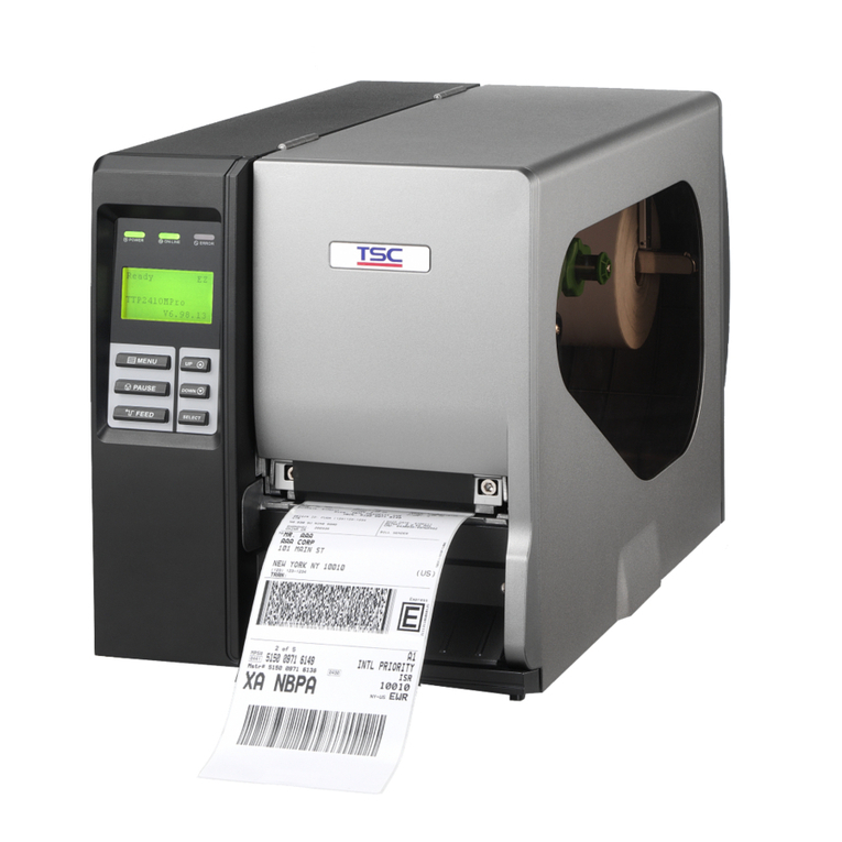
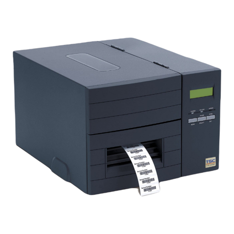
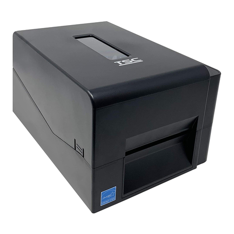
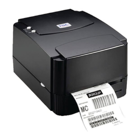
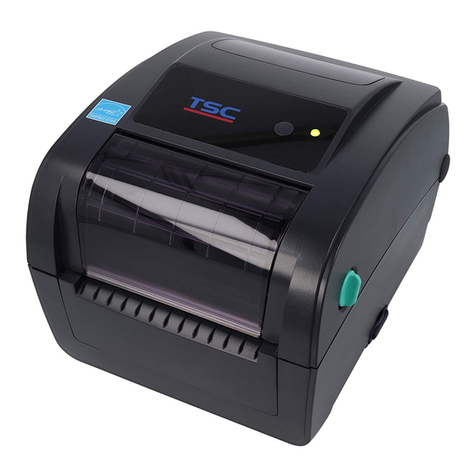
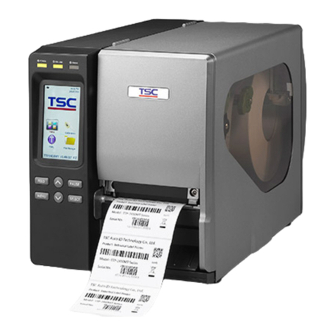
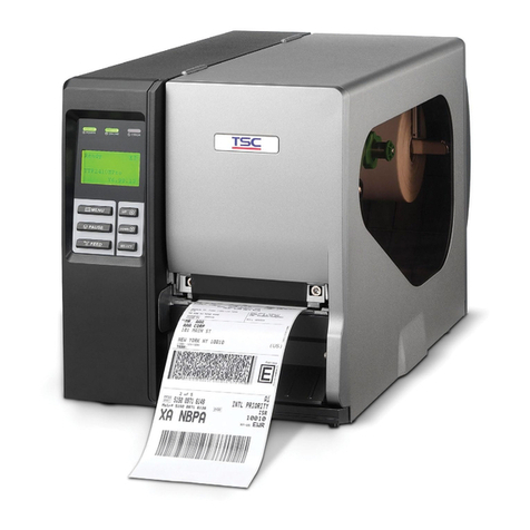
TSC TTP 246M User manual

TTP 246M/344M
SERVICE
MANUAL
THERMAL TRANSFER / DIRECT THERMAL
BAR CODE PRINTER

i
TTP-246M/344M Bar Code Printer
Service Manual
TABLE OF CONTENT
1. FoundamentalsAbout the System..............................................................................1
1.1Printer Overview........................................................................................................1
1.1.1 Front View........................................................................................................1
1.1.2 Rear View ........................................................................................................1
1.2 Pinter Specification...................................................................................................2
1.3 Available Bar Codes.................................................................................................4
2. Supply Specifications .................................................................................................5
2.1 Label Specification ...................................................................................................5
2.2 Ribbon Specification.................................................................................................5
3.Circuit Description.......................................................................................................7
3.1 PCB Function...........................................................................................................7
3.2 MCU PIN Description............................................................................................... 9
3.3 Reset Circuit........................................................................................................... 11
3.4 Memory Circuit....................................................................................................... 11
3.5 Decoder Circuit and Memory Map.......................................................................... 12
3.6 Print Head Circuit...................................................................................................15
3.7 Motor Circuit...........................................................................................................16
3.8 Cutter Circuit..........................................................................................................16
3.9 Parallel Port Circuit................................................................................................. 17
3.10 Serial Port Circuit .................................................................................................17
3.11 USB Circuit...........................................................................................................18
3.11.1 Gap/Black Mark sensor.....................................................................................18
3.11.2 Case Open Sensor............................................................................................19
3.11.3 Ribbon End Sensor...........................................................................................19
3.11.4 Head Open Sensor............................................................................................20
3.11.5 Peel-off Sensor..................................................................................................20
3.12 Summary of PCB connectors......................................................................... 21
3.12.1 TTP-246M & 344M PCB Top Side.....................................................................22
3.12.2 TTP-246M & 344M PCB Bottom Side...............................................................23
4. Mechanism...............................................................................................................24
4.1 Remove Covers, LCD Panel and Lower Front Panel.............................................24
4.2 Replacing the All Harness on Main PCB................................................................28
4.3 Replacing Power Supply Unit.................................................................................29
4.4 Replacing Belt and Gears ...................................................................................... 30
4.5 Replacing Ribbon Rewind Spindle ......................................................................... 33
ii
TTP-246M/344M Bar Code Printer
Service Manual
4.6 Replacing Ribbon Supply Spindle ..........................................................................35
4.7 Replacing Label Supply Spindle.............................................................................37
4.8 Replacing Platen.................................................................................................... 39
4.9 Replacing Stepping Motor......................................................................................41
4.10 Replacing Print Head ...........................................................................................42
4.11 Replacing Print Head Adjustment Knob................................................................43
4.12 Replacing Gap / Black Mark Sensor..................................................................... 45
4.13 Replacing Ribbon Sensor.....................................................................................48
4.14 Replacing Print Head Lift Sensor .........................................................................50
4.15 Replacing Internal Print Server Module................................................................51
4.16 Peeler Kit Installation (Option).............................................................................. 54
4.17 Loading Label For Peel-off Mode.........................................................................60
4.18 Cutter Module Installation (Option)....................................................................... 63
5. POWER ON UTILITIES............................................................................................64
5.1 Calibrate Gap/Black Mark Sensor..........................................................................64
5.2 Self-test..................................................................................................................64
5.3 Printer Initialization.................................................................................................65
6. Troubleshooting........................................................................................................67
7. MAINTENANCE.......................................................................................................69
Update History..............................................................................................................70

1
TTP-246M/344M Bar Code Printer
Service Manual
1. FOUNDAMENTALS ABOUT THE SYSTEM
1.1Printer Overview
1.1.1 Front View
Fig. 1.1 Printer Front View
1.1.2 Rear View
Fig. 1.2 Printer Rear View
Aux. LED
LCD Display
Printer Right
Side Cover
External Label
Feed Opening
Centronics Port
RS-232C Port
Power Switch
Power Supply
Connector
Keys

2
TTP-246M/344M Bar Code Printer
Service Manual
1.2 Pinter Specification
Item
Specification
Printing Mode
Thermal transfer and direct thermal
Resolution
203DPI(TTP246M), 300 DPI (TTP344M)
Max. Print Length
1000 mm (TTP246M), 460 mm (TTP344M)
Max. Print Width
108 mm (TTP246M), 104 mm (TTP344M)
Print Speed
3,4,5,6 ips (TTP246M); 2,3,4 ips (TTP344M)
Environment
Temperature
5 ~40 OC
Humidity
30 ~ 85 %
Temperature
-10 ~ 60 OC
Humidity
20 ~ 95 %
Ventilation
Free air environment
Electrical
Sensors
Label gap sensor, ribbon end sensor, black mark
sensor, head open sensor, label taken sensor
Interface
RS-232C (RS422/485 option), Centronics (SPP),
USBV1.1 and internal LAN adapter (option).
Cutter
4 inch width (Paper thickness up to 0.25 mm)
Power
100-240 V universal switching power supply.
Other
Real Time Clock
CPU
HITACH SH2 7040A
TPH
246M KPC-108-8TA01
344M KPC-106-12TA01
Stepping Motor
KH42JM2B165
Compliance
CE, UL/CUL, BSMI, FCC Class A, TÜ V-GS
Memory
Flash ROM (2MB), DRAM (2MB) and 8M optional flash
ROM (memory module)

3
TTP-246M/344M Bar Code Printer
Service Manual
Communication Interface
Communication
RS-232C (DB-9) at 2400, 4800, 9600 or 19200 baud
rate
Word Length
7 or 8 data bits, 1 or 2 stop bits, selectable parity
Communication Protocol
XON/XOFF and DSR/DTR
Parallel Port
Standard parallel interface
Input Buffer
10KB
RS-232 Interface Pin Configuration
Host
Function
9 Pin
25 Pin
9 Pin
Printer Function
1
+5V
RxD
2
3
2
TxD
TxD
3
2
3
RxD
DTR
4
20
4
DSR
GND
5
7
5
GND
DSR
6
6
6
RDY
RTS
7
4
7
N/C
CTS
8
5
8
RDY
9
+5V
Cutter off Mini-DIN Connector Pin Assignment
Mini-DIN
PCB JP10 connector
Pin 1
Pin 1, brown
Pin2
Pin 3, red
Pin 3
Pin 2, orange
Pin 4
Pin 4, yellow
Peeler Mini-DIN Connector Pin Assignment

4
TTP-246M/344M Bar Code Printer
Service Manual
Mini-DIN
PCB JP20 connector
Pin 5
Pin 1, brown
Pin 6
Pin 2, red
Pin 7
Pin 3, orange
Pin 8
Pin 4, yellow
1.3 Available Bar Codes
Code 39
Code 39C
Code 93
Code128 subsets A.B.C
Codabar
Interleave 2 of 5
EAN-8
EAN-13
EAN-128
UPC-A
UPC-E
EAN and UPC 2(5) digits add-on
CPOST
MSI
PLESSEY
POSTNET
EAN-14
ITF-14
PDF-417
Maxicode
DataMatrix
QR code

5
TTP-246M/344M Bar Code Printer
Service Manual
2. SUPPLY SPECIFICATIONS
2.1 Label Specification
Item
Specification
Type
Roll and label (Continuous, die-cut, fan-fold, ticket and
tag is option)
Label Width
25.4~116 mm ( 1”~4.4” )
Label Length
TTP-246M 10~1000 mm ( 0.4”~39.33” )
TTP-344M 10~460 mm (0.4”~18”)
Label Thickness
0.06~0.25 mm
Label Roll Diameter
203 mm (Max.)
Roll Up Method
Print surface wound outside as standard.
Roll Core Diameter
25 or 77 mm
Black Mark Width
3 mm ( Min.)
2.2 Ribbon Specification
Item
Specification
Ribbon Width
25.4~114.3 mm
Ribbon Length
300 m (Max.)
Note: The maximum length of ribbon depends on its thickness and core outside
diameter.
The formula below defines the correlation between ribbon roll length and ribbon core
diameter.
t4 )d(D
=L 22
, where

6
TTP-246M/344M Bar Code Printer
Service Manual
L = Ribbon length
D = Max. roll diameter
d = Ribbon core outside diameter
t = Ribbon thickness

7
TTP-246M/344M Bar Code Printer
Service Manual
3.CIRCUIT DESCRIPTION
3.1 PCB Function
The mainboard of TTP-344M/246M includes nine system blocks.
1. Memory System
2. Sensor System
3. Decoder System
4. RTC, EEPROM, LCD System
5. Print Head Connector System
6. Motor System
7. Power System
8. USB System
9. Communication Port

8
TTP-246M/344M Bar Code Printer
Service Manual
The figure below shows the PCB system areas:
Fig.3.1 System Block of PCB
Communication
Port
Memory
System
MCU
Sensor
System
RTC,
EPROM
, LCD
Print
Head
Connector
Decoder
USB
System
Power
System
Motor
System

9
9
TTP-246M/344M Bar Code Printer
Service Manual
3.2 MCU PIN Description
A. The Function is follow 40-0220001-02 PCB version.
Port
I/O
High
Low
Function
Instruction
PD0~PD15
I/O
Data D0~D15
Data bus
PC0~PC15
O
Address A0~A15
Address bus
PB0~PB1
O
Address A16~A17
Address bus
PB6~PB9
O
Address A18~A21
Address bus
PB2
O
Active
/RAS
DRAM control signal
PB.3
O
Active
/CASL
DRAM control signal
PB.4
O
Active
/CASH
DRAM control signal
PB5
O
Read
Write
RDWR
DRAM control signal
PA0
I
RXD0
RS232 RX
PA1
O
TXD0
RS232 DX
PA2
I
Active
IRQ0
/Select In
PA3
O
PA3
RS232 CTS
PA4
O
TXD1
TPH Data In
PA5
O
SCK1
TPH Clock
PA6
O
Active
/CS2
CS2
PA7
O
Active
/CS3
CS3
PA8
I
Active
IRQ2
Centronic port /AF
PA9
I
Active
IRQ3
USB interrupt
PA10
O
Active
/CS0
CS0
PA11
O
Active
/CS1
CS1
PA12
O
Active
/WRL
Write Low Byte
PA13
O
Active
/WRH
Write High Byte
PA14
O
Active
/RD
Read
PA15
O
Active
PA15
TPH Latch
PE0
O
Active
PE0
TPH Strobe 1
PE1
O
Active
PE1
TPH Strobe 2
PE2
O
Enable
PE2
LED 1 (L1)
PE3
O
Active
PE3
TPH Power Enable
PE4
I
Enable
PE4
Menu Key
PE5
O
Enable
PE5
LED 2 (L2)

10
10
TTP-246M/344M Bar Code Printer
Service Manual
PE6
I
TIOC2A
Ribbon Near End Sensor
PE7
O
Enable
PE7
LED 3 (L3)
PE8
I
TIOC3A
Paper Near End Sensor
PE9
I/O
PE9
EEPROM SDO&SDI
PE10
O
Enable
PE10
EEPROM Chip Select
PE11
O
PE11
EEPROM Clock
PE12
I/O
PE12
USB Suspend
PE13
I
Enable
PE13
Pause Key
PE14
I
Enable
PE14
Feed Key
PE15
I
Enable
PE15
Head Sensor
PF0
I
AN0
TPH Voltage
PF1
I
AN1
TPH Temperature
PF2
I
Enable
PF2
Cutter Sensor
PF3
I
PF3
RS232 RTS
PF4
I
Enable
PF4
Peel Sensor
PF5
I
Enable
PF5
Ribbon End Sensor
PF6
I
Enable
PF6
Black Mark Sensor
PF7
I
Enable
PF7
Gap Sensor
NMI
I
Active
NMI
Power Down
/WDTOVF
O
Active
(Reserve)
B. Other define
1. Crystal is 7.15909 MHz.
2. Option mode is mode 1. ( MD0 is high, MD1 is low. )
3. Clock mode is PLL ON x 4. ( MD2 is low, MD3 is high. )
4. Vcc is 5V, AVcc is 5V.

11
11
TTP-246M/344M Bar Code Printer
Service Manual
3.3 Reset Circuit
This is reset circuit. The 80846 is voltage detecting IC. It can detect the voltage while the
voltage is up to 4.6V;its output signal is high.
3.4 Memory Circuit
There are 2MB DRAM and 2MB flash ROM on board.
JP7 is memory card connector. The memory card can be expanded to 8MB.

12
12
TTP-246M/344M Bar Code Printer
Service Manual
3.5 Decoder Circuit and Memory Map
The CPLD is used to decode the memory and other function.
Please refer to the memory map below.

13
13
TTP-246M/344M Bar Code Printer
Service Manual
Memory Map

14
14
TTP-246M/344M Bar Code Printer
Service Manual
Definition of other decode function

15
15
TTP-246M/344M Bar Code Printer
Service Manual
3.6 Print Head Circuit
STB1, and STB2 are the print head heating signal. There is a limit for RC heating time of
U15 (74HC123), it can avoid the print head over-heating.
U26 is used to protect print head and avoid the current appears in the improper time.

16
16
TTP-246M/344M Bar Code Printer
Service Manual
3.7 Motor Circuit
This is motor circuit. U12 and U13 are drivers to control the bipolar stepping motor by using
full step control method
3.8 Cutter Circuit

17
17
TTP-246M/344M Bar Code Printer
Service Manual
U15B (74HC123) controls the breaking of U14. U14 is the driver of cutter’s DC motor.
3.9 Parallel Port Circuit
Centronics port is SPP mode and one-way communication.
3.10 Serial Port Circuit
U18 (SP232A) is RS232 asynchronous communication driver IC.
U19 is used for industrial long-distance asynchronous communication;U19 is optional for
RS-422/485.
Other manuals for TTP 246M
1
Table of contents
Other TSC Barcode Reader manuals

TSC
TSC 4D200 Series User manual

TSC
TSC TTP 244M Pro Series User manual

TSC
TSC TTP-245C series User manual

TSC
TSC TTP-244 series User manual

TSC
TSC Alpha-30L Series User manual

TSC
TSC TTP-243 Series User manual

TSC
TSC MH240 User manual

TSC
TSC MX340P Series User manual

TSC
TSC Alpha-30L Series User manual

TSC
TSC TTP-342M Plus User manual

TSC
TSC TTP-245C series User manual

TSC
TSC Prontronix TTP-244CE User manual

TSC
TSC ME240 series User manual

TSC
TSC TTP-243 Pro Series User manual

TSC
TSC TTP-342ME Pro User manual

TSC
TSC TTP-2410MU Series User manual

TSC
TSC TDP-244 Series User manual

TSC
TSC PRINTRONIX TX210 Series User manual

TSC
TSC TDP-225 User manual

TSC
TSC Alpha-4L Series User manual