TSC TTP-244 Plus User manual

THERMAL TRANSFER BAR CODE PRINTER
TTP-244 Plus
TTP/TDP 244/342
Service
Manual

i
TTP-244 Plus Bar Code
Printer Service Manual
Table of Contents
1. FUNDAMENTALS ABOUT THE SYSTEM ..................................................................1
1.1 Features of the TTP/TDP-244 Plus ............................................................................1
1.2 Model Naming Syntax............................................................................................1
1.3 Overview ....................................................................................................................2
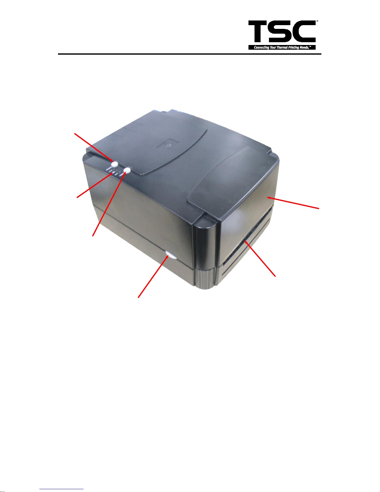
1.3.1 Front View...........................................................................................................2
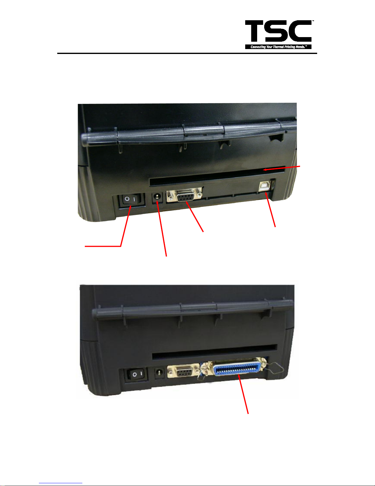
1.3.2 Rear View...........................................................................................................3
1.4 Basic Specifications....................................................................................................4
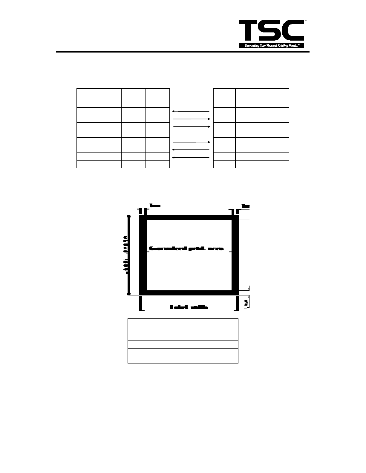
1.5 Effective Print Area.....................................................................................................5
1.6 Available Bar Codes...................................................................................................5
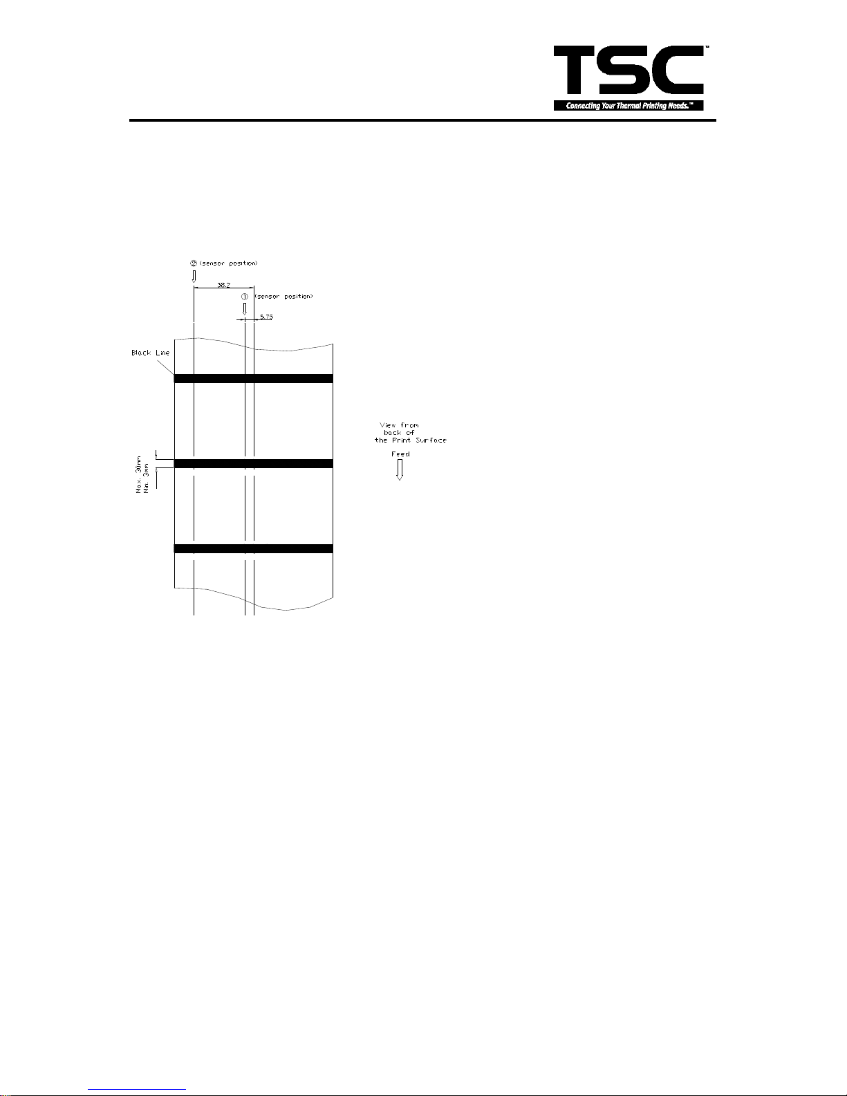
1.7 Various Sensors.........................................................................................................6
2. SUPPLY SPECIFICATIONS.............................................................................................8
2.1 Types of Paper...........................................................................................................8
2.2 Specifications.............................................................................................................8
2.3 Ribbon Sizes and Shapes ........................................................................................10
3. ELECTRONICS ..............................................................................................................11
3.1 Summary of Board Connectors ................................................................................11
3.2 Pin Configuration......................................................................................................13
4. MECHANISM..................................................................................................................15
4.1 Mainboard Replacement...........................................................................................15
4.2 DC Motor Replacement............................................................................................17
4.3 Print Head Replacement ..........................................................................................21
4.4 Ribbon Rewind Spindle Encoder Replacement ........................................................23
4.5 Felt Fabric Replacement ..........................................................................................24
4.6 Stepping Motor Replacement...................................................................................26
4.7 Black Mark Sensor / Gap Sensor (Receiver) Replacement ......................................27
4.8 Ribbon Sensor (Receiver) Replacement...................................................................28
4.9 Ribbon Sensor (Transmitter) / Gap Sensor (Transmitter) Replacement ...................30

ii
TTP-244 Plus Bar Code
Printer Service Manual
4.10 Platen Replacement...............................................................................................31
5. TROUBLE SHOOTING................................................................................................... 33
5.1 Trouble Shooting......................................................................................................33
5.2 Calibrate the Gap Register.......................................................................................34
5.3 Self-test....................................................................................................................34
5.4 Ram Clear................................................................................................................34
5.5 Diagnosis Operation Procedure................................................................................34
5.6 Testing Sensors .......................................................................................................35
UPDATE HISTORY ............................................................................................................36

1
TTP-244 Plus Bar Code
Printer Service Manual
1. FUNDAMENTALS ABOUT THE SYSTEM
1.1 Features of the TTP/TDP-244 Plus
1. TTP-244 Plus bar code printer prints bar codes, characters, logos, on various types of labels
and tickets by direct thermal or thermal transfer printing.
2 TTP-244 Plus adopts a “BASIC-like” high level programming language to help users
programme the desired label forms with ease.
3. TTP-244 Plus bar code printer can be connected to a personal computer or an optional LCD
keyboard to execute the programs downloaded in the printer’s memory. The printer is
equipped with the following standard devices:gap transmissive sensor, black mark reflective
sensor and ribbon end sensor.
4. TTP-244 Plus bar code printer provides a selection of optional features, including portable LCD
keyboard, etc.
1.2 Model Naming Syntax
T T P –2 4 4 Plus
(1) (2) (3) (4)
(1) Print method:
TTP –Thermal Transfer Printing
TDP –Thermal Direct Printing
(2) Resolution of print head (DPI)
(3) Maximum print width (Inch)
(4) Maximum print speed (Inch/Sec)

2
TTP-244 Plus Bar Code
Printer Service Manual
1.3 Overview
1.3.1 Front View
Label Dispense
Opening
Cover Release Button
Top Cover
FEED Button
PAUSE ButtonPAUSE Button
PWR., ON-LINE
and ERR.
Indicators

3
TTP-244 Plus Bar Code
Printer Service Manual
1.3.2 Rear View
Power Supply
Connector
RS-232 Interface
Connector
USB Interface
Connector
Label Insert
Opening (for use
with external
labels)
Power On/Off
Switch
Centronics Interface
Connector (Option)

4
TTP-244 Plus Bar Code
Printer Service Manual
1.4 Basic Specifications
Thermal transfer and direct thermal printing
High dot density printing (203 dots/inch)
Selectable print speeds at 2.0”, 3.0” or 4.0” per second
Supports RS-232 and USB interface
Maximum media width up to 4.49”(114 mm)
Adjustable label edge guide
International character sets
Print area is 4.09”W x 40”L (without any file downloaded in the printer memory)
User selectable bar code ratios and heights
Prints on labels or tickets
Equipped with black mark sensor
Label stock and thermal transfer ribbon are easy to install
Internal label print counter
Self test and hex dump mode
Downloadable fonts from label design software
Electronics/Communication Specifications
Electrical
DC Motor: DC24V
Memory:
─DRAM: 8 Mb
─Flash: 2 Mb
Adapter 100~240VAC10%, 50~60Hz
Regulations: FCC Class A, CE Class A, C-Tick Class A, TÜ V/GS, CCC
Communications Interface:
* RS-232/USB
* RS-232/Centronics (factory option)

5
TTP-244 Plus Bar Code
Printer Service Manual
RS-232 Interface Pin Configuration:
Host Function
9 Pin
25 Pin
9 Pin
Printer Function
1
+5V
RxD
2
3
2
TxD
TxD
3
2
3
RxD
DTR
4
20
4
DSR
GND
5
7
5
GND
DSR
6
6
6
RDY
RTS
7
4
7
N/C
CTS
8
5
8
RDY
9
+5V
1.5 Effective Print Area
Label/Ticket Length
12mm~2286mm
Effective Print
Length
10mm~2284mm
Label/Ticket Width
25mm~103mm
Effective Print Width
23mm~101mm
No Print Area
1mm
1.6 Available Bar Codes
1D bar code:
Code 39
Code 93
Code 128 UCC
Code 128, Subsets A, B, and C

6
TTP-244 Plus Bar Code
Printer Service Manual
Codabar
Interleaved 2 of 5
EAN-8, EAN-13, EAN-128
UPC-A, UPC-E
EAN and UPC with 2 or 5 digits add-on
MSI
Postnet
Plessey
China POST
2D bar codes:
Maxicode
DataMatrix
PDF-417
QR code
1.7 Various Sensors
Feed Gap Sensor
The feed gap sensor detects a label gap to locate the starting print position of the next
label. The sensor is mounted 4 mm off the center line of the main mechanism.
In case of Label
Black Mark Sensor
The black mark sensor locates the position of label by emitting infrared rays onto the
black mark at the back of the ticket. The sensor is mounted 5.75 mm off the center line
of the ticket roll width on the mechanism.

7
TTP-244 Plus Bar Code
Printer Service Manual
In case of Ticket
The default sensor position is (1) as shown on the figure below. To change to the (2)
position, the customer should notify the manufacturer in advance. There can be only
one position for the sensor. Once the sensor position is agreed upon, it can not be
changed afterwards.
Ribbon End Sensor
The sensor detects the end portion of the ribbon. The ribbon end must be transparent.
Label End Sensor
The sensor detects the end portion of the label.
Ribbon encoder
The encoder is used to detect if the ribbon is broken.

8
TTP-244 Plus Bar Code
Printer Service Manual
2. SUPPLY SPECIFICATIONS
2.1 Types of Paper
Two types of media are available for TTP-244 Plus: label and ticket.
In TTP-244 Plus, there are two types of sensors for paper: gap sensor and black mark
sensor.
Label and ticket can be further classified into direct thermal type or thermal transfer type.
2.2 Specifications
Items
Label
Paper Width
Max.114mm
Min. 25.4mm
Length (Pitch)
10~1016mm
Paper
Thickness
0.25 mm
Paper Weight
Max 240 g/m2
Max. Roll
Diameter
(1” core)
Inner roll diameter. Max 4.3” (110mm)
External roll diameter. Max 8.4”
(214mm)
Roll Up Method
Print surface wound outside as
standard
Paper Core ID.
25.7±0.3mm
Note:
(1). The width and thickness quoted above are said of the label plus its backing paper.
(2). Likewise, the approval of label entails that of its backing paper.
(3). Paper shape is as shown on next page:

9
TTP-244 Plus Bar Code
Printer Service Manual

10
TTP-244 Plus Bar Code
Printer Service Manual
2.3 Ribbon Sizes and Shapes
Item
Specifications
Ribbon shape
Spool type
Ribbon width
Max. 110mm
Min. 40mm
Ribbon winding width
Max. 110mm
Min. 40mm
Leading tape
Polyester film, 3355mm long
End tape
Polyester film (transparent), 2505mm
long
Max. ribbon OD.
67mm
Winding method
Ink surface to be wound outside
Note: The maximum length of ribbon depends on its thickness and core outside diameter.
The formula below defines the correlation between ribbon roll length and ribbon core
diameter.
t4 )d(D
=L 22
, where
L = Ribbon length
D = Max. roll diameter
d = Ribbon core outside diameter
t = Ribbon thickness

11
TTP-244 Plus Bar Code
Printer Service Manual
3. ELECTRONICS
3.1 Summary of Board Connectors
Main board
Connector
Description
Remark
1
Ribbon sensor connector
JP18
2
Black mark sensor connector
JP46
Pin
Description
Voltage
1
Power
5V
2
Black mark
sensor receiver
No paper or black mark : 3.1~3.2V
Detect paper: 0~0.3V
3
GND
0V
1
2
3
9
6
7
12
8
4
10
13
5
14
11

12
TTP-244 Plus Bar Code
Printer Service Manual
3
Gap sensor connector
JP53
Pin
Description
Voltage
1
GND
0V
2
Gap sensor emitter
Emitter on : 0.7~1.8V
Emitter off: 2.4~2.7V
3
Power
5V
4
GND
0V
5
Gap sensor receiver
No paper or gap: 3.1~3.2V
Detect paper: 0~0.3V
6
Power
5V
4
Ribbon encoder sensor & DC motor connector
JP37
5
Stepping motor connector
JP14
6
Print head connector
JP42
7
SD memory card module connector
JP44
8
Micro processor
U2
9
Power switch
SW2
10
Power supply output (24V DC) connector
B3
11
RS-232C connector
JP7
12
Centronics port connector (Option)
JP4
13
USB connector
JP9
14
Push button connector
JP52
Pin
Description
Voltage
1
LED green (PWR)
LED light on: 2.0~2.2V
LED light off: 0~0.3V
2
LED green (ONLINE)
LED light on: 2.0~2.2V
LED light off: 0~0.3V
3
LED red (ERR)
LED light on : 2.0~2.2V
LED light off: 0~0.3V
4
Pause switch
0V: Push key
3.3V: Stand-by
5
Feed switch
0V: Push key
3.3V: Stand-by
6
GND
0V

13
TTP-244 Plus Bar Code
Printer Service Manual
3.2 Pin Configuration
RS-232C
PIN
CONFIGURATION
1
+5 V
2
TXD
3
RXD
4
CTS
5
GND
6
RTS
7
N/C
8
RTS
9
N/C
USB
PIN
CONFIGURATION
1
N/C
2
D-
3
D+
4
GND
Centronics
Pin
SPP Mode
Nibble
In/Out
Function
1
Strobe
N/A
In
A low on this line indicates that there are valid data
at the host. When this pin is de-asserted, the +ve
clock edge should be used to shift the data into the
device.
2-9
Data 0-7
N/A
In
Data Bus. Single-directional.
10
Ack
N/A
Out
A low on this line indicates that there are valid data
at the Device. When this pin is de-asserted, the
+ve clock edge should be used to shift the data into
the host.
11
Busy
N/A
Out
When in reverse direction, a high indicates data,
while a low indicates a command cycle. In forward
direction, it functions as PtrBusy.
12
Paper Out /
End
N/A
Out
When low, device acknowledges reverse request.
13
Select
N/A
Out
Extensibility flag
14
Ground
N/A
GND
15
No Defined
N/A
N/A
16-17
Ground
N/A
GND
Ground
18
No Defined
N/A
N/A
19-30
Ground
N/A
GND
Ground
31
No Defined
N/A
N/A

14
TTP-244 Plus Bar Code
Printer Service Manual
32
Error / Fault
N/A
Out
A low set by the device indicates that the reverse
data is available
33-35
Ground
N/A
GND
Ground
36
No Defined
N/A
N/A

15
TTP-244 Plus Bar Code
Printer Service Manual
4. MECHANISM
4.1 Mainboard Replacement
1. Turn off the printer power.
2. Remove the power cord and RS-232 and/or USB port cable.
3. Open the top cover of the printer.
4. Remove the four screws of the internal label roll mount.
Remove screws of the label roll mount
5. Move the mechanism about 5 mm in the label feed direction.
6. Take out the internal label roll mount.
Internal label
roll mount

16
TTP-244 Plus Bar Code
Printer Service Manual
7. Remove all connectors on the main board.
Remark
Description
JP52
Push button connector
JP37
Ribbon encoder sensor & DC motor connector
JP14
Stepping motor connector
JP53
Gap sensor connector
JP46
BLine sensor connector
JP18
Ribbon sensor connector
JP42
Print head connector
8. Remove the screw of ground wire on the main board.
9. Remove the rest three screws on the mainboard.
10. Replace the mainboard.
11. Reassemble the internal label roll mount in the reverse procedures of the removal.
Ground Wire
JP52
JP14
JP53
JP37
JP46
JP18
JP42

17
TTP-244 Plus Bar Code
Printer Service Manual
4.2 DC Motor Replacement
1. Turn off the printer power.
2. Remove the power cord and RS-232 and/or USB port cable.
3. Open the top cover of the printer.
4. Remove the printer front panel.
5. Remove the screws in the lower left, lower right corners of the main mechanism.
6. Remove all four screws of the internal label roll mount.
Screws
Table of contents
Other TSC Printer manuals

TSC
TSC TTP-286MT Series User manual

TSC
TSC Alpha-2R Series User manual

TSC
TSC TDM-20 User manual

TSC
TSC TTP-2410MT Series User manual

TSC
TSC PEX-1120 Series User manual

TSC
TSC Alpha-3R User manual

TSC
TSC TA300 Series User manual

TSC
TSC TTP-225 Series User manual

TSC
TSC TTP-2410M User manual

TSC
TSC TDP-245 Series User manual

TSC
TSC TE200 series User manual

TSC
TSC TTP-245 series User manual

TSC
TSC DA200 Series User manual

TSC
TSC Alpha-3R User manual

TSC
TSC MB340 Series User manual

TSC
TSC Printronix MB240 Series User manual

TSC
TSC TTP-245 series User manual

TSC
TSC TTP-384M User manual

TSC
TSC Console User manual

TSC
TSC TSC-30 Series User manual