TurnOnGreen FSP Series Manual

Copyright © 2021. TurnOnGreen Technologies, a subsidary of TurnOnGreen, Inc. All Rights Reserved.
FSP1200 120KW
Standalone Fast Charger
User Manual & Installation Instructions
FSP Series


CONTENT
Introductions ����������������������������������������������������������������������������� 1
Features ������������������������������������������������������������������������������������ 1
Applications ������������������������������������������������������������������������������� 1
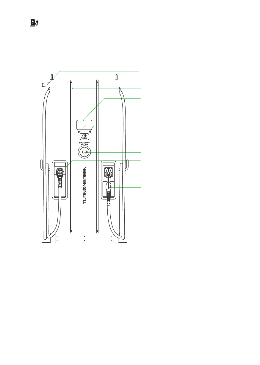
1� Basic User Interface ��������������������������������������������������������������� 2
2. Specication �������������������������������������������������������������������������� 3
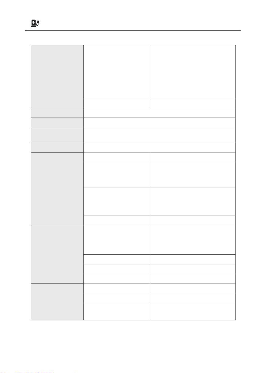
2.1 Product Specication ������������������������������������������������������ 3
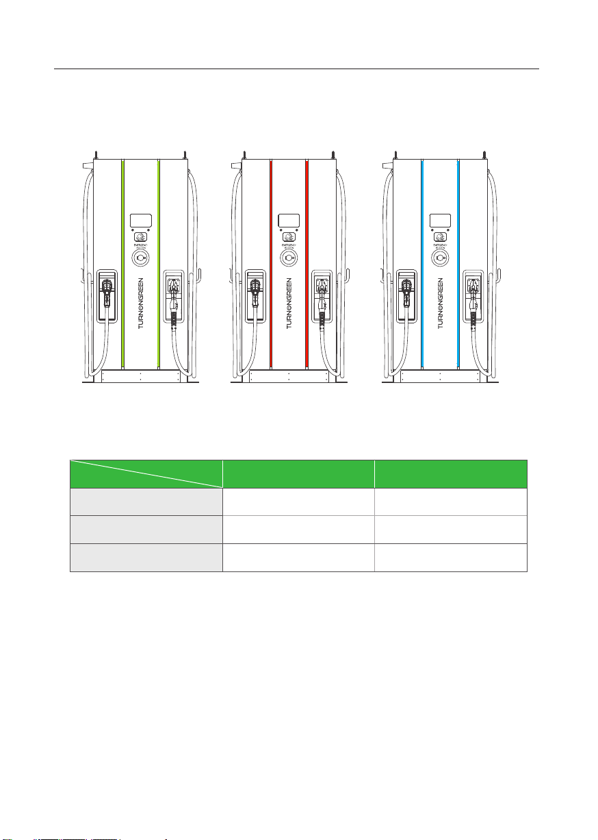
2�2 FPS 1200 Version Description ����������������������������������������� 6
2�3 LED Indication and Operation Status �������������������������������� 7
2�4 Dimensions ��������������������������������������������������������������������� 8
2�5 Direction of cooling Airflow ���������������������������������������������� 8
3� Installation Instruction ����������������������������������������������������������� 9
3�1 Before Installation ����������������������������������������������������������� 9
3�2 Grounding and Safety Requirement �������������������������������� 10
3�3 Unpack the charger �������������������������������������������������������� 12
3�4 Recommended Tools for Installation and Inspection ������� 15
3�5 Installation Procedure ���������������������������������������������������� 16
3�6 Installation Inspection & Commissioning ����������������������� 21
4� Network Setting ������������������������������������������������������������������� 24
4�1 Wi-Fi Network Setting ���������������������������������������������������� 24
4�2 3G/4G Setting ���������������������������������������������������������������� 26
4�3 Time setting ������������������������������������������������������������������ 28
5� Operation Process ���������������������������������������������������������������� 30
5�1 Operating Sequence ������������������������������������������������������� 30
5�2 Operating Procedure ������������������������������������������������������ 30
5�3 Troubleshooting ������������������������������������������������������������ 35
5�4 Status Codes ����������������������������������������������������������������� 35
6� Maintenance ������������������������������������������������������������������������ 56
6�1 General Maintenance ����������������������������������������������������� 56
6�2 Replacement Kits and Accessories ��������������������������������� 59
7� Limited Product Warranty ����������������������������������������������������� 60
Appendix - Package list ������������������������������������������������������������ 61

Introductions
Features
• Pluggable power modules make installation easy and flexible.
• Offers customers the convenience of start/stop charging control from an autho-
rized RFID smart card or mobile APP.
• Built according to the latest industry standards for DC charging.
• Carries an outdoor rating capable of withstanding solid and liquid intrusions in
outdoor settings making the unit more stable and highly reliable.
• Provides a high-contrast, screen interface with multi-function buttons.
Applications
• Public and Private Parking Areas
• Community Parking Areas
• Parking Areas of Hotels, Supermarkets and Shopping Malls
• Workplace Parking Areas
• Charging Stations
• Highway Rest Areas
The Standalone DC Fast Charger is the top choice to power battery electric vehicles
(BEV) and plug-in hybrid electric vehicles (PHEV). It is designed for quick charging
in both public and private locations, such as retail and commercial parking spaces,
fleet charging stations, highway service areas, workplace, residence, etc.
The Standalone DC Fast Charger has the advantage of easy installation. The
wall-mounted design and pluggable power modules realize flexible and cost-ef-
fective installation for different types of locations. The DC Standalone charger also
has network communication capability. It is able to connect with remote network
systems and provide drivers of electric cars real-time information, such as the lo-
cation of charging stations, charging progress and billing information. The Stand-
alone DC Fast Charger has a clear user interface with function buttons, safety cer-
tifications and an excellent waterproof and dust proof design to provide the best
choice for outdoor environments.
1

1. Basic User Interface
Antenna for Wi-Fi & 3G/4G
LED Indication
7" Information Screen
Right Button & Left Button
RFID Card Reader
• Charging Status
• Alarm information
• User Authorization
Emergency Stop
Left DC Connector
Right DC Connector
*The connectors installed on
the EVSE may vary depending
on the model(section 2.2)
2
POWERING POSITIVE CHANGEPOWERING POSITIVE CHANGE

2. Specication
2.1 Product Specication
Model Name FSP1200 Series
AC
INPUT
Voltage Rating 3Φ480Vac(+10%,-15%)
Max. Input Current 170A@277Vac,L-N
190A@235Vac,L-N
Electrical Distribution 3P+ N+ PE (Wye conguration)
Power Grid System TN/TT and IT
Frequency 50/60Hz
Max. Input Power 129kVA
Power Factor > 0.99
Efciency > 94%, at optimize V/I point
DC
OUTPUT
Dual Output CCS1 and CHAdeMO
Output Voltage Range CCS1 150Vdc ~ 950Vdc
CHAdeMO 150Vdc ~ 500Vdc
Maximum Output Current
**CCS1
200A@150Vdc ~ 500Vdc when
output voltage up to 950Vdc the
output current is 126A
**CHAdeMO
120A@150Vdc ~ 500Vdc
Maximum Output Power DC 120kW
Simultaneously output
mode
0% , 50% , 100%
*Each connector will get 50%
output power when plug in
simultaneously; And one connector
will get 100% when another
connector nish the charging
session or only this connector is
plugged in.
Voltage Accuracy ±2%
Current Accuracy ±2%
Electrical Isolation Isolation between Input and Output
Standby Power < 100W
3

Communication External
Ethernet, Wi-Fi and 3G or 4G
4G Frequency Band:
LTE FDD : B2/B4/B5/B12/B13/
B14/B66/B71
3G Frequency Band:
WCDMA : B2/B4/B5
Internal CAN Bus/ RS485
Input Protection OVP, OCP, OPP, UVP, RCD, SPD
Output Protection OCP, OVP, LVP, OTP, IMD
Internal Protection OTP, AC contactor detection, DC contactor detection, Fuse
detection
Load Management Via OCCP 1.6 JSON
User Interface &
Control
Display 7-inch LCD
Button
Right Button : Select charging
connector.
Left Button : Home / Stop charge
User Authentication
RFID Support ISO 14443A/B, ISO
15693, FeliCa Lite-S (RCS966),
OCPP, 2D barcode, APP, Mobile
Payment
Backend Support OCPP 1.6 JSON
Environmental
Conditions
Operation Temperature
-30°C to 50°C (-22°F to 122°F),
power
derating from 50°C (122°F) and
above
Storage Temperature -40°C to 70°C (-40°F to 158°F)
Relative Humidity 5%~95% RH, non-condensing
Altitude ≤ 2000m(6560 ft)
Regulations
Safety UL2202,UL2231
EMI/EMC UL2202
Charging Interface CHAdeMO Ver 1.2
CCS DIN 70121
4
POWERING POSITIVE CHANGE

Mechanical
Specications
Dimensions (WxDxH mm) 800x650x1900mm (32x26x75
inches )
Weight (typ.) <500kg (1102 lbs) with two
charging guns
DC Charging Connector CCS1,CHAdeMO or GB/T
Cooling Fan Cooling
Ingression Protection IP55 NEMA 3R
Anti-vandalism IK10,
not include LCD & RFID cover
5

Left DC Connector Right DC Connector
2.2 FSP1200 Version Description
The FSP1200 series are available in different versions depending on the charging
connectors, below table shows the available combinations, the corresponding
position of charging connectors are indicated from left to right in the view of front
charger.
Version Left DC Connector AC Connector Right DC Connector
FSP1200 CHAdeMO -CCS1
FSP1200 CCS1 - -
FSP1200 CCS1 -CCS1
0 : none
1 : IEC 62196-2 Type 1/SAE J1772 Plug
2 : IEC 62196-2 Type 1/SAE J1772 Socket
3 : IEC 62196-2 Type 2 Plug
4 : IEC 62196-2 Type 2 Socket
5 : GB/T AC Plug
6 : GB/T AC Socket
7 : CCS2 AC Plug
J : CHAdeMO
U : Natural cooling CCS1 combo
V : Liquid cooling CCS1 combo
E : Natural cooling CCS2 combo
F : Liquid cooling CCS2 combo
G : GBT DC
6
POWERING POSITIVE CHANGE

Standby Fault Charging
7
2.3 LED Indication and Operation Status
Status LED Left Indicator Right Indicator
Standby Green Green
Fault Red Red
Charging Blue Blue

8
POWERING POSITIVE CHANGE
2.5 Direction of cooling Airflow
Air OutAir In
2.4 Dimensions
Main Size of Charger:(Unit: mm)
800 650
1900

9
• Read all the instructions before using and installing this product.
• Do not use this product if power cable or charging cable have any damage.
• Do not use this product if the enclosure or charging connector are broken or
open or if there is damage.
• Do not put any tool, material, finger or other body part into the charging connec-
tor or EV connector.
• Do not twist, swing, bend, drop or crush the charging cable. Never drive over it
with a vehicle.
• Power feed must be 3 Phase Wye configuration with TN(-S)/ TT grounding sys-
tems.
• In the installation of TN(-S) system: the neutral (N) and the PE of the power dis-
tribution are directly connected to the earth. The PE of the charger equipment is
directly connected to the PE of power distribution and separate conductor for PE
and neutral (N).
• In the installation of TT system: the neutral (N) and the PE of the power distribu-
tion are directly connected to the earth. The PE of the charger equipment is iso-
lated to the PE of power distribution to the earth.
• The capacity of power supply should be higher than 129kVA in order to function
correctly.
• The product should be installed in free air area and keep at least 30cm (12 inch-
es) clearance distance to all air vent of the product.
• Need sufficient space for product installation and maintenance, please keep not
less than 107cm (42 inches) clearance distance from all around the product.
3. Installation Instruction
3.1 Before Installation
Warning: The product should be installed only by a licensed contractor
and/or licensed technician in accordance with all building codes, elec-
trical codes and safety standards.
Warning: The product should be inspected by a qualified installer prior
to initial use. Under no circumstances will compliance with the infor-
mation in this manual relieve user of his /her responsibilities to comply
with all applicable codes and safety standards.

10
POWERING POSITIVE CHANGE
• The product must be connected to a grounded, metal, permanent wiring system.
Connections shall comply with all applicable electrical codes. Recommend the
ground resistance be less than 10Ω.
• Ensure no power is connected at all times when installing, servicing, or maintain-
ing the charger.
• Use appropriate protection when connecting to main power distribution network.
• Use appropriate tools for each task.
3.2 Grounding and Safety Requirement
CAUTION: The disconnect switch for each ungrounded conductor of
AC input shall be provided by installation contractor or technician.
CAUTION: A cord extension set or second cable assembly shall not be
used in addition to the cable assembly for connection of the EV to the
EVSE.
NOTICE
It is recommended to conduct WI-Fi and 4G signal strength while
charger installation. The RSSI (Received Signal Strength Indication)
value is considered as good as higher than -65dBm. Poor connec-
tion quality might interrupt charging process or data transaction.

11
3�2�1 Service Wiring
• Ground Connection
Always connect the Neutral at the service to Earth Ground. If ground is not pro-
vided by the electrical service then a grounding stake must be installed nearby.
The grounding stake must be connected to the ground bar in the main breaker
panel and Neutral connected to Ground at that point.
• 480Vac Three-Phase(Line to Line)
CAUTION!
This is feed from Y-connection power grid, the Standalone DC Fast
Charger can connect to L1, L2 or L3, and Neutral. Earth ground must be
connected to neutral at only one point, usually at the breaker panel.
480V Three-Phase Wiring Connection
WARNING!
Earth Connection is Essential!
PE
277V 277V
277V
480V
Neutral
T
R
S
DANGERS
Be Aware of High Voltage!

12
POWERING POSITIVE CHANGE
WARNING!
Charger weight might be 420 kg. Charger with package
might be 520 kg. Be careful during unpack process.
3.3 Unpack the charger
1. The product is direct current (DC) charger and the packing design passed the
packaging simulation test. If the packaging damage caused by overturning, fall-
ing or external impact during transportation, it may cause the product damage
or defects. If there is any serious damage to the packaging when receiving the
goods, please notify the supplier about your findings.
2. The product is delivered by transport company to warehouse or specified loca-
tion where it will be handed over. Transporting the charger to its final location
(last mile service) is not standard included in the order.
3. NOTICE: The delivery truck unloads the pallet carrying the charger. The move-
ment of the charger to its final location is the responsibility of the customer /
contractor.
If the TiltWatch indicator is red (tilted over 80°)
1. Do not refuse the shipment / receipt.
2. Make a notation on the delivery receipt and inspect cabinet for damage.
3. If damage is discovered, leave cabinet in original package and request imme-
diate inspection from carrier within 3 days of delivery.
4. Contact the supplier by mail or phone to address your findings.

13
Remove the surrounding boards
STEP 1�
STEP 2�
Remove the carton and packing cushion and film.

14
POWERING POSITIVE CHANGE
Remove these 6 pcs of fixing M12 screws.
STEP 3�
To use lifting eye bolts to move the EVSE,please appply 6mm(1/4 inches )di-
ameter steel wire rope to the four eye bolts as following picture.
STEP 4�
> 800mm (31.5”)

15
3.4 Recommended Tools for Installation and
Inspection
3�4�1 Recommended Tools for Installation
Type Description
Philips Screwdriver No. 2 and 3
Shifting Wrench
Socket Screwdriver No. 8 and 10 and 17 and 19
Electrical Tape Black / 15mm (0.6”) Width
AC Input Cable 95mm²(188 kcmil) at least Cable ×5 (L1,L2,L3,N,PE)
recommend 600V,90°C,XLPE power cablee
Ring Terminal
1.Ring Terminal for L1, L2, L3, N(Inner Diameter:
10.5mm (0.41”), Outer Diameter: 28.5mm (1.12”))
2. Ring Terminal for PE (Inner Diameter: 10.5mm
(0.41”), Outer Diameter: 28.5mm (1.12”))
Crimping Pliers for Ring
Terminal Hexagonal
Wire Stripper
Wire Cutters
Crane / Forklift <500kg(1102 lbs)
3�4�2 Recommended Tools for Inspection & Commissioning
Type Description
EV or EV Simulator Meet CHAdeMO/CCS Standard
Multiple Meter 1000V
Current Probe 400Amp
RFID Authorized Card
RFID No Valid Card
Door Key
Needle-Nose Plier
Laptop or PC & CAT6 cable For Charger Configuration
Wi-Fi /4G signal quality checker Recommended

16
POWERING POSITIVE CHANGE
3.5 Installation Procedure
STEP 1�
1. Build 1090mm x 750mm x 200mm (42.91” x 29.53”x 7.87”) concrete base on
the level to stand charger in advance.
2. Implant AC input cable conduit less than Φ102mm(eg.3” PVC conduit),and
SFTP Ethernet cable conduit less than Φ34mm (eg. 1” PVC conduit).
3. And implant 4 pcs of M12 screw stick out the concrete base for 40 mm (1.57”)
to fix the charger. The positioning of these 4 pcs of M12 screws should be
within ±2 mm (0.08”) in short axis, ±8 mm (0.32”) in long axis according to
screw holes of charger.
4. To fit this positioning requirement, a steel plate fixture be suggested. Please
create the fixture by the following drawing or order this fixture from your ven-
dor.
5. The other way to fix the charger on concrete base is install 2 of L-brackets
accessories outside of charger and drill the screw holes (Φ16 mm (0.63”)) on
the cement base as drawing below.
3�5�1 Build Concrete Base
L Bracket Orifice
L Brscket Orifice
4XM12 Screw stick
Ethernet Cable at least 1800mm(71 inch)
AC Cable at least 500mm(19.69 inch)
*The distance should be Sufficient for maintenance from the wall

17
200.0(7.87")
1090.0(42.91")
890.0(35.03")
690.0(27.17")
750.0(29.53")
475.0(18.70")
470.0(18.50")
270.0(10.63")
140.0(5.51")
137.5(5.41")
100.0(3.94")
200.0(7.87")
347.7(13.69)
467.7(18.41")
6XØ16MM(0.63")
(L Bracket orifice)
4xM12 SCREW STICK
Ø102MM(4.02")
(For AC cable Conduit)
Ø34MM(1.34")
(For Ethernet Cable Conduit)
STEP 2�
• Extend 3 phase 5 wires AC input cables from conduit of concrete base, AC
cables expose at least 500mm (19.69”) and these 5 wires should be with ring
terminals (L1, L2, L3 & N : Inner Diameter : 10.5mm (0.41”), Outer Diameter
: 28.5mm (1.12”) & PE : Inner Diameter : 10.5mm (0.41”), Outer Diameter :
28.5mm (1.12”)).
• The conductor cross sectional area of input power wires should be not
less than 95mm² (212 kcmil). If internet is connected via Ethernet, at least
1800mm (71”) of the Ethernet cable must be exposed from the conduit.
Other manuals for FSP Series
1
This manual suits for next models
1
Table of contents
Other TurnOnGreen Batteries Charger manuals