manuals.online logo
Brands
  1. Home
  2. •
  3. Brands
  4. •
  5. Tyco Electronics
  6. •
  7. Tools
  8. •
  9. Tyco Electronics 1338744-1 User manual

Tyco Electronics 1338744-1 User manual

Other Tyco Electronics Tools manuals

Tyco Electronics 90390-3 User manual

Tyco Electronics

Tyco Electronics 90390-3 User manual

Tyco Electronics ERGOCRIMP User manual

Tyco Electronics

Tyco Electronics ERGOCRIMP User manual

Tyco Electronics 1372039-1 User manual

Tyco Electronics

Tyco Electronics 1372039-1 User manual

Tyco Electronics AMPACT 602080 User manual

Tyco Electronics

Tyco Electronics AMPACT 602080 User manual

Tyco Electronics CERTI- CRIMP 90720- 1 User manual

Tyco Electronics

Tyco Electronics CERTI- CRIMP 90720- 1 User manual

Tyco Electronics 549043-1 User manual

Tyco Electronics

Tyco Electronics 549043-1 User manual

Tyco Electronics 7-0528441-6 User manual

Tyco Electronics

Tyco Electronics 7-0528441-6 User manual

Tyco Electronics 8-528030-1 User manual

Tyco Electronics

Tyco Electronics 8-528030-1 User manual

Tyco Electronics 59239-4 User manual

Tyco Electronics

Tyco Electronics 59239-4 User manual

Tyco Electronics CXP 2161060-1 User manual

Tyco Electronics

Tyco Electronics CXP 2161060-1 User manual

Tyco Electronics ERGOCRIMP User manual

Tyco Electronics

Tyco Electronics ERGOCRIMP User manual

Tyco Electronics 871087 Reference guide

Tyco Electronics

Tyco Electronics 871087 Reference guide

Tyco Electronics 411-15684 User manual

Tyco Electronics

Tyco Electronics 411-15684 User manual

Tyco Electronics AMP 231652 Series User manual

Tyco Electronics

Tyco Electronics AMP 231652 Series User manual

Popular Tools manuals by other brands

AGI Westfield MKX16 Assembly manual

AGI

AGI Westfield MKX16 Assembly manual

GYS HAND-DUCTION 056923 Translation of the original instructions

GYS

GYS HAND-DUCTION 056923 Translation of the original instructions

Grizzly H7583 instruction manual

Grizzly

Grizzly H7583 instruction manual

Sealey VS0462.V2 instructions

Sealey

Sealey VS0462.V2 instructions

Makita HR2650 instruction manual

Makita

Makita HR2650 instruction manual

Forza 1100H Series manual

Forza

Forza 1100H Series manual

Aventics EBS-PI operating instructions

Aventics

Aventics EBS-PI operating instructions

Martor SECUNORM 175 quick start guide

Martor

Martor SECUNORM 175 quick start guide

jbc N4473 instruction manual

jbc

jbc N4473 instruction manual

FEINMETALL FZWZ-SET-001 quick start guide

FEINMETALL

FEINMETALL FZWZ-SET-001 quick start guide

Worx Professional Sonicrafter WU676 Original instructions

Worx Professional

Worx Professional Sonicrafter WU676 Original instructions

Gage Bilt GB713SH Original instructions

Gage Bilt

Gage Bilt GB713SH Original instructions

Hilti DX 9-ENP Original operating instructions

Hilti

Hilti DX 9-ENP Original operating instructions

norbar NORTRONIC 34399 Operator's manual

norbar

norbar NORTRONIC 34399 Operator's manual

BGS technic 8578 manual

BGS technic

BGS technic 8578 manual

axing BWZ 5-02 Operation instructions

axing

axing BWZ 5-02 Operation instructions

Makita DHR241 instruction manual

Makita

Makita DHR241 instruction manual

Motor Guard JMB-1250 instructions

Motor Guard

Motor Guard JMB-1250 instructions

manuals.online logo
manuals.online logoBrands
  • About & Mission
  • Contact us
  • Privacy Policy
  • Terms and Conditions

Copyright 2025 Manuals.Online. All Rights Reserved.

Instruction Sheet
Housing Removal Tool 408--8393
LOC B
1of 2
E2010 Tyco Electronics Corporation, Harrisburg, PA
All International Rights Reserved
TE logo and Tyco Electronics are trademarks.
*Trademark. Other products, logos, and company names used are the property of their respective owners.
TOOLING ASSISTANCE CENTER 1--800--722--1111
PRODUCT INFORMATION 1--800--522--6752
This controlled document is subject to change.
For latest revision and Regional Customer Service,
visit our website at www.tycoelectronics.com
02 FEB 10 Rev A1338744- 1
Figure 1
Insertion
Adjuster Rod
Socket Head
Screw
Side Push Bars
Screw
Clamp
Upper
Clamp
Lower
Clamp
1. INTRODUCTION
Housing Removal Tool 1338744--1 shown in Figure 1
is designed to remove the receptacle housing from a
6-- or 10--row Z--PACK* HM or HS3 backplane
receptacle connector on a printed circuit (pc) board.
The removal tool is designed for use in Pistol Grip
Manual Handle Assembly 58074--1. For set up and
operation of the manual hand assembly, refer to
instruction sheet 408--6790.
Dimensions on this instruction sheet are in metric
[with U.S. customary units in brackets]. Figures
are not drawn to scale.
Reasons for reissue of this instruction sheet are
provided in Section 7, REVISION SUMMARY.
2. DESCRIPTION
When properly inserted into the manual handle
assembly, the removal tool will clamp the receptacle
housing while removing it from the remaining part of
the connector. Features of the removal tool and their
functions are as follows:
Upper and Lower Clamps — used to clamp the housing
into the removal tool.
Screw Clamp — used to adjust the clamps for the
different housing sizes.
Insertion Adjuster Rod — used to mount into the manual
handle assembly and to adjust stroke length.
Side Push Bars — used to push on the pc board.
3. ADJUSTMENT
If the removal tool requires more travel to remove the
receptacle housing, remove the removal tool from the
manual handle assembly and turn the insertion
adjuster rod counterclockwise to increase the travel.
This setting is normally pre--set and will not need
adjustment.
4. HOUSING REMOVAL PROCEDURE
1. Select the connector that requires housing
removal.
2. Position the removal tool over the connector as
shown in Figure 2.
3. Using the screw clamp, close the upper clamp
onto the housing until the latches on the clamps
lock behind the front edge of the housing and the
connector is held firmly with the tool. See Figure 2.
4. Activate the manual handle assembly. This will
remove the housing from the remaining part of the
connector.
5. Loosen the screw clamp, and remove the
connector from removal tool.
Figure 2
Screw
Clamp Clamp
Latch Front Edg
e
of Housing
Housing
NOTE
i
NOTE
i
408- 8393
Housing Removal Tool 1338744- 1
Rev A2 of 2 Tyco Electronics Corporation
5. MAINTENANCE AND INSPECTION
5.1. Daily Maintenance
It is recommended that each operator of the removal
tool be made aware of, and responsible for, the
following steps of daily maintenance:
1. Remove dust, moisture, and other contaminants
with a clean brush or a soft, lint--free cloth.
2. Make sure all components are in place and
properly secured.
3. Actuate the removal tool to ensure all
mechanisms of the tool move smoothly.
5.2. Periodic Inspection
Regular inspections should be performed by quality
control personnel. A record of scheduled inspections
should remain with the removal tool or be supplied to
personnel responsible for the removal tool. Though
recommendations call for at least one inspection a
month, the inspection frequency should be based on
the amount of use, ambient working conditions,
operator training and skill, and established company
standards. These inspections should include a visual
inspection and should be performed in the sequence
listed:
1. Remove any accumulated dirt and debris that
could affect the operation of the removal tool.
2. Make sure all components are in place and are
properly secured.
3. Check for chipped, cracked, worn, or broken
areas. If damage is evident, repair is necessary.
See Section 6, REPLACEMENT AND REPAIR.
6. REPLACEMENT AND REPAIR
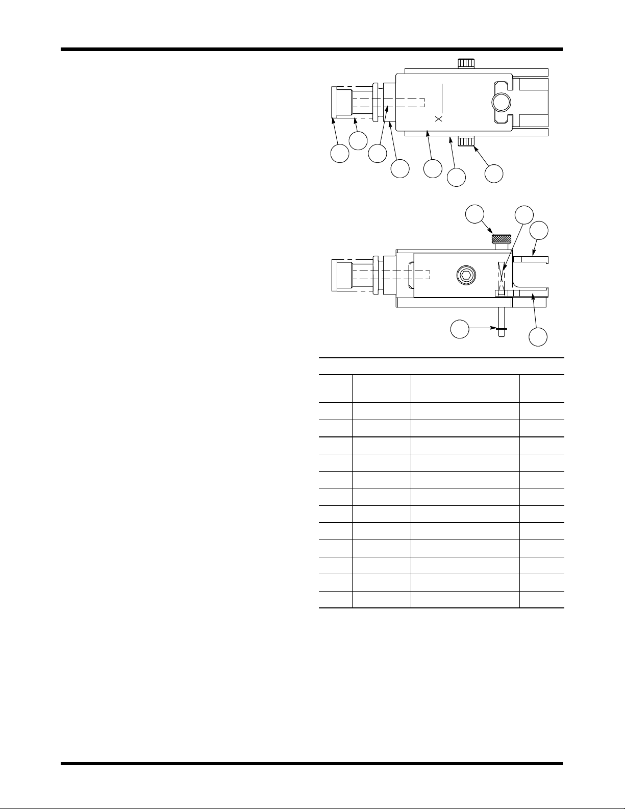
Replacement parts are listed in Figure 3. Parts other
than those listed in Figure 3 should be replaced by
Tyco Electronics to ensure quality and reliability of the
removal tool. Order replacement parts through your
representative, or call 1--800--526--5142, or send a
facsimile of your purchase order to 1--717--986--7605,
or write to:
CUSTOMER SERVICE (38--35)
TYCO ELECTRONICS CORPORATION
PO BOX 3608
HARRISBURG PA 17105--3608
For customer repair service, call 1--800--526--5136.
1
2
3
4 5 67
12
11
10
9
8
REPLACEMENT PARTS
ITEM PART
NUMBER DESCRIPTION QTY PER
TOOL
1-- 312149--1 ROD, Insertion Adjuster 1
2-- 0 22488--5 SPRING, Compression 1
31--21007--2 SCREW, Set 1
41320254--1 HEAD, Machined 1
51338748--1 BAR, Drive 1
61338749--1 BAR, Side Push 2
7-- 0 21000--7 SCREW, Socket Head Cap 2
8-- 21986--4 RING, Retaining 2
91320261--1 SCREW, Clamp 1
1002--22278--1 SPRING, Compression 2
1101338753--1 CLAMP, Upper 1
1201338754--1 CLAMP, Lower 1
Figure 3
7. REVISION SUMMARY
Revisions to this instruction sheet include:
SUpdated instruction sheet to corporate
requirements