Instruction Sheet
Cr mp ng D e Assembl es 408-9279
E
2006 yco Electronics Corporation, Harrisburg, PA
All International Rights Reserved
yco is a trademark. * rademark
Other products, logos, and company names used are the property of their respective owners. LOC B
1
of 5
OOLING ASSIS ANCE CEN ER 1-800-722-1111
PRODUC INFORMA ION 1-800-522-6752 his controlled document is subject to change.
For latest revision and Regional Customer Service,
visit our website at
www.tycoelectron cs.com
25 JUL 06 Rev B
90390-3 and 90391-3
PROPER USE GUIDELINES
Cumulative raumaDisorderscanresultfromtheprolongeduseofmanuallypoweredhandtools.Handtoolsareintendedforoccasionaluseandlowvolume
applications. A wide selection of powered application equipment for extended-use, production operations is available.
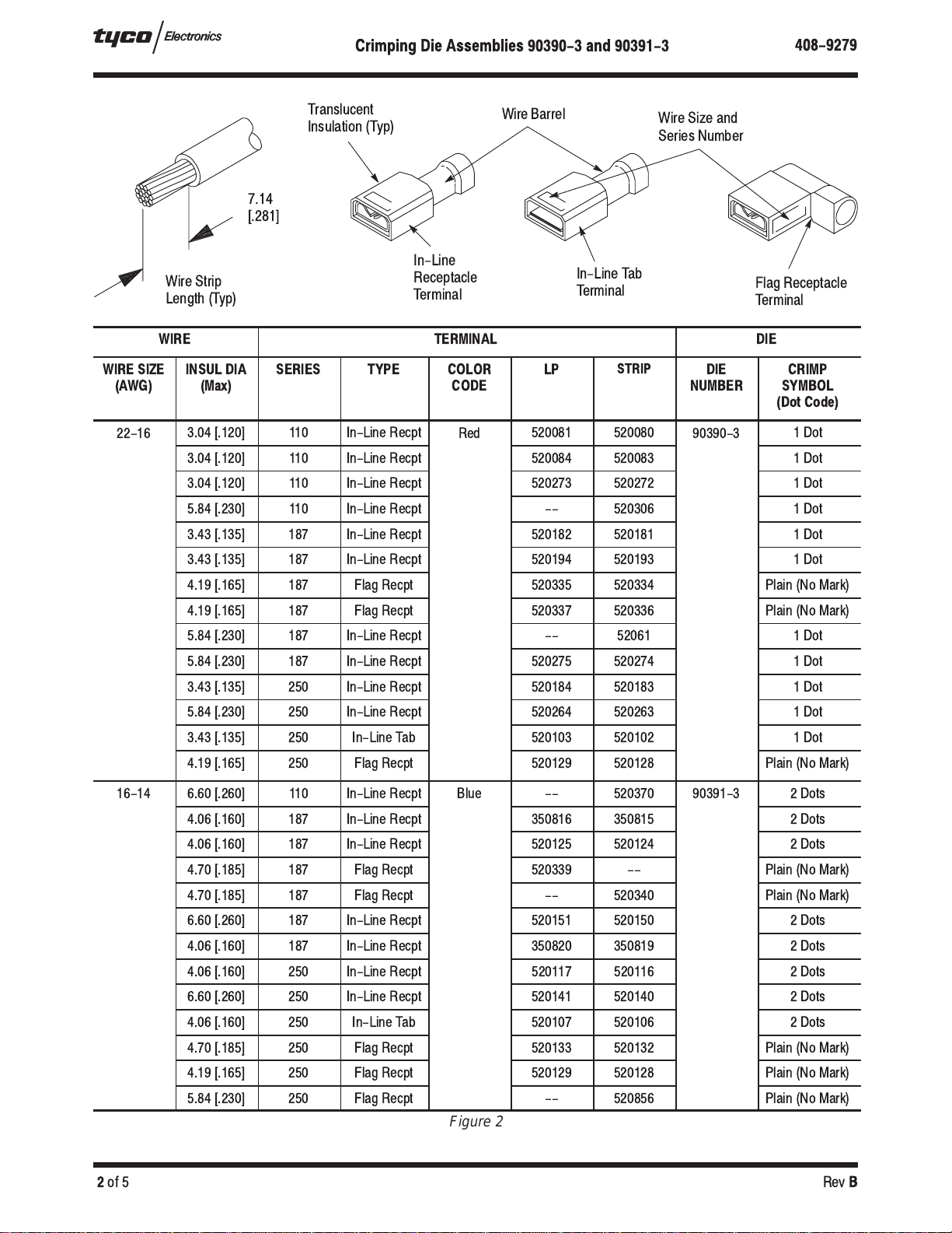
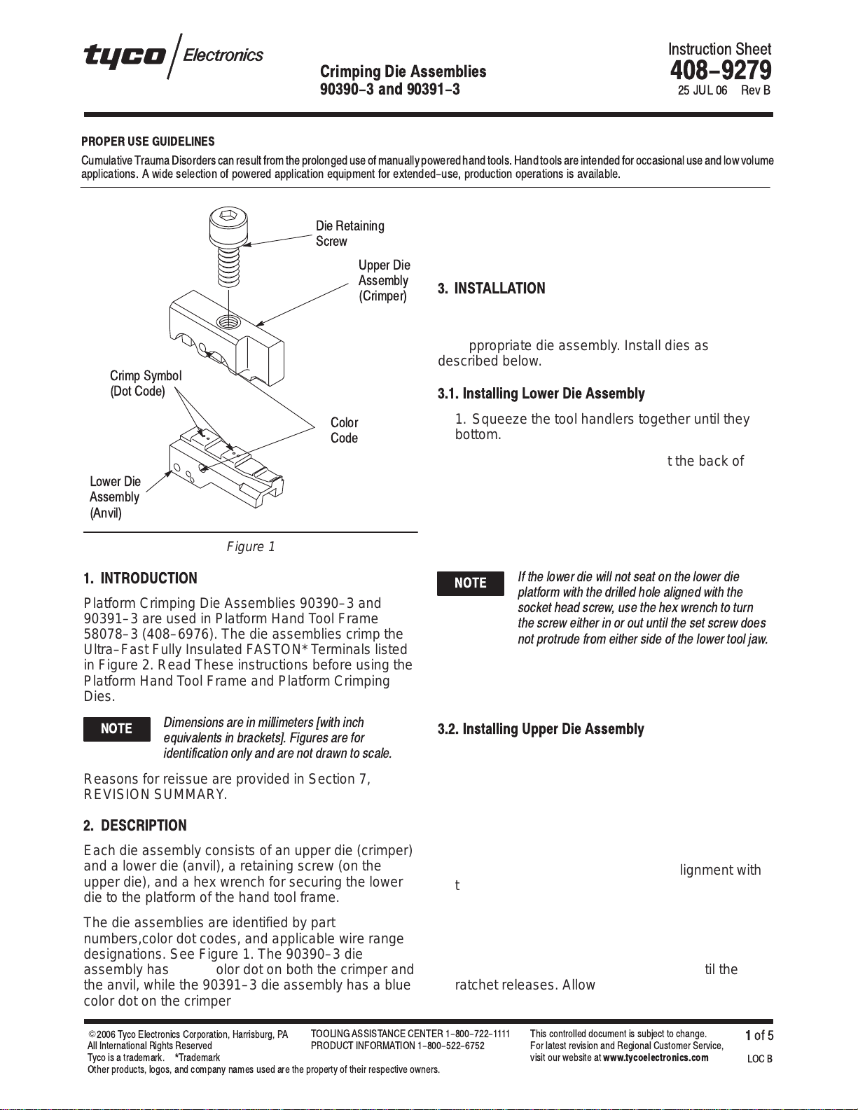
Figure 1
Die Retaining
Screw
Upper Die
Assembly
(Crimper)
Lower Die
Assembly
(Anvil)
Color
Code
Crimp Symbol
(Dot Code)
1. INTRODUCTION
Platform Crimping Die Assemblies 90390–3 and
90391–3 are used in Platform Hand Tool Frame
58078–3 (408–6976). The die assemblies crimp the
Ultra–Fast Fully Insulated FASTON* Terminals listed
in Figure 2. Read These instructions before using the
Platform Hand Tool Frame and Platform Crimping
Dies.
Dimensions are in millimeters [with inch
equivalents in brackets]. Figures are for
identification only and are not drawn to scale.
Reasons for reissue are provided in Section 7,
REVISION SUMMARY.
2. DESCRIPTION
Each die assembly consists of an upper die (crimper)
and a lower die (anvil), a retaining screw (on the
upper die), and a hex wrench for securing the lower
die to the platform of the hand tool frame.
The die assemblies are identified by part
numbers,color dot codes, and applicable wire range
designations. See Figure 1. The 90390–3 die
assembly has a red color dot on both the crimper and
the anvil, while the 90391–3 die assembly has a blue
color dot on the crimper and the anvil. The color
coding on the die assembly corresponds to the color
coding on translucent insulation of the Ultra–Fast
FASTON terminal for easier identification when
crimping.
3. INSTALLATION
Determine the part number of the terminal you are
crimping, then refer to the table in Figure 2 and select
the appropriate die assembly. Install dies as
described below.
3.1. Install ng Lower D e Assembly
1. Squeeze the tool handlers together until they
bottom. Then allow them to open fully.
2. Hold the hand tool frame so that the back of the
tool is facing you and note the socket head screw
located in the lower die platform. See Figure 3.
3. Slide the lower die onto the lower platform,
ensuring that the drilled holes on the side of the
lower die line up with the socket head screw.
If the lower die will not seat on the lower die
platform with the drilled hole aligned with the
socket head screw, use the he wrench to turn
the screw either in or out until the set screw does
not protrude from either side of the lower tool jaw.
4. With the lower die in place, turn the socket head
screw (on the die platform) clockwise until snug.
Do NOT overtighten.
3.2. Install ng Upper D e Assembly
1. Remove the die retaining screw from the die
assembly.
2. Position the upper die in upper die platform of
the tool. Thread the die retaining screw through the
mounting hole in the top of tool and tighten the
screw until it is snug but NOT secured.
3. While guiding the upper die into alignment with
the lower die, slowly close the tool handles until the
dies bottom.
4. Tighten the upper die retaining screw until the
die is secure.
5. Squeeze the tool handles together until the
ratchet releases. Allow the tool handles to open
fully. The tool is now ready for use.
NOTE
NOTE