408–9767
Modular Plug Hand Tool (Premium Grade) 231652–[ ]
5of 7Rev H
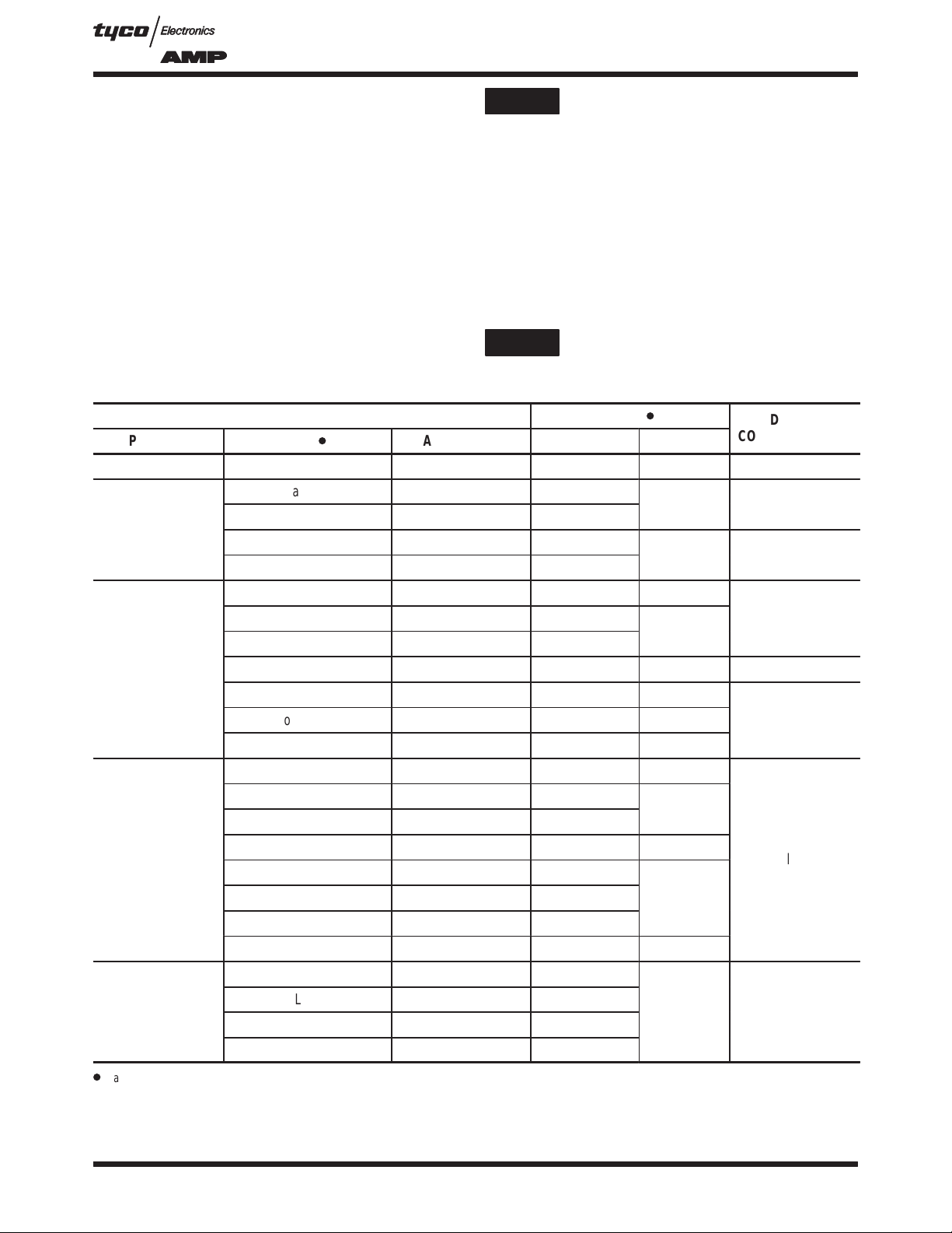
BladeSet–Up
Gage(Ref)
MovableBlade
Assembly
Screw
(2Places)
Adjusting Flat Oval Cable Stripper
Figure 7
6.4 [.25] (Length)
Screw (2 Places)
FixedBlade
SupportPlate
Cable(Ref)
MovableBlade
SupportPlate
9.7 [.38] (Length)
Screws (2 Places)
MovableBlade
Assembly
BeveledEdges
of Blades Face
Inward
FixedBlade
Assembly
Replacing Blades in Flat Oval Cable Stripper
DO NOT cycle the tool without a die in place.
Damage to the stripping blades may occur.
CAUTION
Die Set Must Be
Installed in Tool
3. Insert Blade Set–Up Gage 231667–2 (available
separately and part of Blade Replacement Kit
231662–4) or a 1.02 [.040] shim between the
stationary and movable blades. Slide the movable
blade against the gage or shim, and tighten the
screws.
The recommended shim thickness does not
account for larger than normal conductor
insulation. Adjust the blade gap according to your
specificneeds.
5.3. Replacing Flat Oval Cable Stripper Blades (Figure 7)
If the flat oval cable stripper blades are worn or
damaged, replace the fixed blade assembly and
movable blade assembly according to the following.
1. Remove the four screws holding both blades in
place. Remove fixed blade assembly and movable
blade assembly from tool.
2. Position new blades onto tool with beveled
edges facing inward.
3. Install and tighten screws. Adjust flat oval cable
stripper according to Paragraph 5.2.
DO NOT cycle the tool without a die in place.
Damage to the stripping blades may occur.
6. MAINTENANCE AND INSPECTION
Inspect the tool and die set immediately upon arrival
at your facility and at regularly–scheduled intervals
thereafter to ensure that they have not been
damaged. When not in use, store tool with handles
closed in a clean, dry area.
Failure to perform daily maintenance and periodic
inspection can cause defective modular plug
terminations,leading to discontinuities on
individualwire circuits.
6.1. Daily Maintenance
Foreign particles should be cleaned from the tool
using a soft, clean, lint–free cloth or brush. Make sure
all pins, rings and other retaining hardware is in place,
and that the die set is undamaged. Lightly lubricate all
pins, pivot points, and bearing surfaces using a good
grade SAE 20 motor oil. DO NOT lubricate
excessively.
DO NOT lubricate surfaces of the die set that
contact the product. These areas must be kept
clean to ensure a usable modular plug assembly.
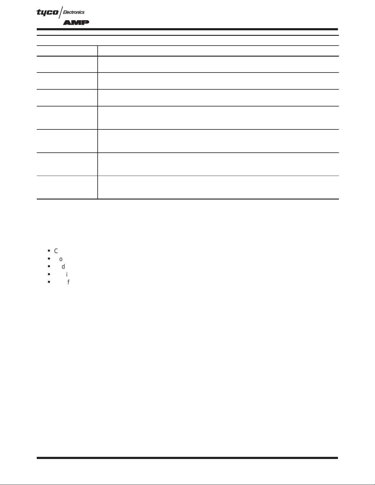
6.2. Periodic Inspection
It is recommended that the following inspections be
conducted at least once a month by quality control
personnel. More frequent inspections should be
conducted if your work environment, company
standards, or amount of tool use indicates the need.
A. Visual Inspection
Remove die set from the tool; then, remove all
lubrication and accumulated film and debris by
immersing the dies and tool head in a mild
commercial degreaser.
1. Check for missing or defective pins, rings, or
other retaining hardware. Replace parts as
necessary.
2. Closely inspect dies for damage, giving special
attention to bearing surfaces and surfaces that
contact the product. Worn, cracked, pitted, or
chipped indenter or nest surfaces, or other obvious
wear or damage to the die set or tool head requires
removal of the affected part from service.
NOTE
CAUTION
CAUTION
CAUTION