manuals.online logo
Brands
  1. Home
  2. •
  3. Brands
  4. •
  5. Tyco
  6. •
  7. Industrial Equipment
  8. •
  9. Tyco GRINNELL F445 User manual

Tyco GRINNELL F445 User manual

- ,
PREACTION SYSTEM. DOUBLE INTERLOCK
ELECTRIC/ELECTRIC RELEASE
MODEL F445 - 2-l/2 INCH (65 mm)
l- Model F445 Automatic
Resetting Deluge Valve
2- Model F52 Swing Check Valve
3- System Main Control Valve
(supervised in open position)
4- System Shut-Off Valve
(supervised in open position)
5- Solenoid Valve
6- Low Air Pressure Alarm Switch
7- Diaphragm Chamber Pressure
Gauge
9 Waterflow Pressure Alarm Switch
9- Manual Control Station
lo- Automatic Air/Nitrogen Pressure
Maintenance Device
1l_ Water Motor Alarm (optional)
12- Cross-Zone Deluge Valve
Releasing Panel with Battery
Back-Up
13- Manual Pull Station (as required)
14- Alarm Bell
15 Heat Detectors (or other fire
detection devices)
16- Automatic Sprinklers
17- Water Supply Pressure Gauge
16 System Air Pressure Gauge
19- F445 Main Drain Valve
20- F52 Main Drain Valve
A- Power Supply To Panel ulm
B- Audible Alarm Circuit
C- Fire Detection Initiating Circuit
(Zone 1)
D- Manual Pull Initiating Circuit
(Zone 1)
E- Low Pressure Alarm Initiating FIGURE A
Circuit (Zone 2)
F- Releasing Circuit MODEL F445 ELECTRIC/ELECTRIC
G- Waterflow Alarm Initiating Circuit DOUBLE INTERLOCK PREACTION SYSTEM
- SCHEMATIC OF TYPICAL ARRANGEMENT-
The 2-l/2 inch (65 mm) Model F445 The F445 Electric/Electric Double In-
Electric/Electric Double Interlock Pre- terlock Preaction System utilizes a
action System (Ref. Figure A) is de- Model F445 Automatic Resetting Del-
signed for use in applications, such as uge Valve and a Model F52 Swing
refrigerated areas, requiring the maxi- Check Valve. The Swing Check Valve
mum degree of protection against in- isolates the Deluge Valve from the
Printed in U.S.A. 1l-97
advertent flooding of the sprinkler sys-
tem piping. system air pressure. The releasing
trim for the Deluge Valve utilizes a
Solenoid Valve, which is operated by
energizing the releasing circuit of a
Cross-Zone Deluge Valve Releasing
Panel (automatic control unit).
Zone 1 of the Releasing Panel is oper-
ated by either a fire detection device or
TDll48
OBSOLETE
manual pull station. Zone 2 of the Re-
leasing Panel is operated by a Low Air
Pressure Alarm Switch in response to
a loss of system air pressure due to the
opening of an automatic sprinkler. The
Solenoid Valve remains closed until it
is electrically energized by the Releas-
ing Panel.
In order for the Double Interlock Pre-
action System to automatically actu-
ate, two independent events must oc-
cur. Zone 1 of the Releasing Panel
must operate upon automatic opera-
tion of the electric fire detection initiat-
ing circuit or manual operation of the
electric-manual pull initiating circuit,
and Zone 2 of the Releasing Panel
must operate via the Low Air Pressure
Alarm Switch upon loss of air pressure
from the sprinkler system piping, due
to operation of one or more sprinklers.
The Double Interlock Preaction Sys-
tem will automatically actuate only
when both Zone 1 and Zone 2 of the
Releasing Panel have operated, which
in turn will energize the Solenoid
Valve. Accidental loss of system air
pressure (for example: a lift truck acci-
dentally dislodges a sprinkler), or op-
eration of just the fire detection circuit
(for example: an accidental operation
of an electric pull station), will only
cause an alarm, and will not actuate
the system or flood the sprinkler sys-
tem piping.
The 2-l/2 inch (65 mm) Model F445
Electric/Electric Double Interlock Pre-
action System is listed by Underwriters
Laboratories Inc. and Underwriters’
Laboratories of Canada as Double In-
terlock Type Water Control Valves,
and they are approved by Factory Mu-
tual Research Corporation as Refrig-
erated Area Systems for use in refrig-
erated rooms or buildings.
WARNING
The 2-1 I2 inch Model F445 Double
Interlock Preaction System with the
associated trim described herein must
be installed and maintained in com-
pliance with this document, as well as
with the applicable standards of the
National Fire Protection Association,
in addition to the standards of any
other Authorities Having Jurisdic-
tion. Failure to do so may impair the
integrity of the associated devices.
The owner is responsible for main-
taining their fire protection system
and devices in proper operating con-
dition. The installing contractor or
manufacturer should be contacted
relative to any questions.
The 2-l/2 inch (65 mm) Model F445
Electric/Electric Double Interlock Pre-
action System, as well as its associ-
ated trim, is rated for use at a minimum
service pressure of 20 psi (1,4 bar)
and a maximum service pressure of
175 psi (12,l bar).
The following is a list of the Technical
Data Sheets for the valves and de-
vices which are required as part of the
Double Interlock Preaction System:
Deluge Valve . . . . . . TD114
Swing Check Valve . . . . . TD318
Solenoid Valve . . . . . . . TD119
Manual Control Station . . . TD121
Low Air Pressure Alarm
Switch . . . . . . . . . . . . TD213
Waterflow Pressure Alarm
Switch . . . . . . . . . . . . TD213
The following is a list of the Technical
Data Sheets for the recommended
system pressure maintenance devices
to be used as part of the Double Inter-
lock Preaction System:
System Pressure Maintenance De-
vice (select one)
-Air Pressure Reducing Type
. . . . . . . . . . . . . . TDlll
-Nitrogen Press. Reducing Type
. . . . . . . . . . . . . . TD113
System Design Considerations
The automatic sprinklers, as well as
the cross-zone deluge valve releasing
panel (automatic control unit), fire de-
tection devices, manual pull stations,
and signaling devices, which are util-
ized with the Electric/Electric Double
Interlock Preaction System must be
UL Listed, ULC Listed, C-UL Listed, or
FM Approved, as applicable.
NOTE
When the Solenoid Valve is energized
via the cross-zone controlpanel to op-
erate the F445 Valve. the Solenoid
Valve must remain energized in order
for the F445 Valve to remain open.
Because a double interlock preaction
system requires time for a drop in sys-
tem air pressure to occur (concurrently
with the response time for the separate
fire detection system), before it will
allow water to enter the system piping,
this system has characteristics similar
to a dry pipe sprinkler system. There-
fore, the system design considerations
for a dry pipe system are normally ap-
plied to a double interlock preaction
system - including a 30% increase in
-2-
design area and prohibition of gridded
system piping.
The deluge valve, swing check valve,
and all interconnecting piping must be
located in a readily visible and acces-
sible location and in an area which can
be maintained at a minimum tempera-
ture of 4O”F/4”C.
NOTE
Heat tracing is not permitted for the
deluge valve, swing check valve, or
any of the interconnecting piping.
Heat tracing can promote the forma-
tion of hardened mineral deposits
which can prevent system operation.
Heat tracing can also result in dam-
age to the F445 Deluge Valve Dia-
phragm Assembly.
In planning the installation, considera-
tion must also be given to the disposal
of the large quantities of water which
may be associated with draining the
system or performing a flow test.
Installation configuration and clear-
ance dimensions are given in Figure B.
The grooved inlet and outlet connec-
tions of the F445, as well as the F52
Swing Check Valve are cut in accord-
ance with Gruvlok standard groove
specifications for steel pipe, and they
are suitable for use with grooved end
pipe couplings that are listed or ap-
proved for fire protection service.
In order to readily perform the System
Inspection Procedure described in the
Care and Maintenance section, it is
recommended that a System Shut-Off
Valve be installed above the Model
F52 Swing Check Valve, as shown in
Figure A. The System Shut-Off Valve
should be a listed or approved (as ap-
propriate) indicating valve with a su-
pervisory switch to monitor the nor-
mally open position.
System Air Pressure Requirements
The recommended system air pres-
sure for the Electric/Electric Double
Interlock Preaction System is nomi-
nally 15 psi (1,O bar), irrespective of
the water supply pressure. The use of
a higher system air pressure may in-
crease water delivery time, and the
use of a lower system air pressure may
prevent clearing the alarm of the Low
Air Pressure Alarm Switch (Item 19 -
Fig. C) on increasing pressure. The
Low Pressure Alarm Switch is field set
to alarm at nominally 12 psi (0,8 bar)
on decreasing pressure. It is recom-
mended that the system air pressure
be maintained by one of the following
methods.
l A maximum 200 psi (13,8 bar) plant
air supply in combination with the
Model F324 Air Maintenance Device
described in TDl 11.
l A maximum 3000 psi (206.9 bar)
OBSOLETE
,2”(01
(300mml
t---- DIAPHRAGM
CHAMBER
SUPPLY
CONNECTIONS .
. 13” I- ,,“(O)
(330mml (275mm) -1
I-- ;:i
dd
l-S/a”
+ (41.3mml
NOTES:
(a.)Minimum clearance, additional 2’ (5Omm) is recommended.
(b.)Refer to Technical Data Sheet TD114 for additional installation dimensions.
(c.)The F445 Deluge Valve I F52 Check Valve riser arrangement is shown for “Flow Right”.
A “Flow Left” arrangement can be obtained by rotating the F445 Valve so that it discharges
to the left and by mounting the F52 Check Valve with Electric/Electric Double Interlock
Preaction Trim to the left of the F445 Deluge Valve. The trim arrangements for electric
actuation shown in TD114 may be installed either “Flow Right” or “Flow Left”.
FIGURE B
INSTALLATION CONFIGURATION AND CLEARANCE DIMENSIONS
nitrogen cylinder in combination with
the Model F328 Nitrogen Mainte-
nance Device described in TD113.
NOTES
It is recommended that the pressure
maintenance device be of a type that
maintains a constant system pres-
sure, i.e., a pressure maintenance de-
vice that utilizes a pressure regulator
versus a pressure switch (e.g., the
F-324 or F328). Use of a pressure
switch operated pressure mainte-
nance device with a cut-in/cut-out
differential may result in a delay in
the operation of the system due to a
fire, because of the cut-out pressure
being higher than the recommended
nominal system air pressure.
The dew point of the air or nitrogen
must be maintained below the lowest
ambient temperature to which the
Double Interlock Preaction System
-3-
piping will be exposed, or as required
by theAuthority Having Jurisdiction.
Introduction of moisture into the sys-
tem piping that is exposed to freezing
temperatures can create ice build up
which could prevent proper operation
of the system.
Friction Loss
The nominal pressure losses versus
flow rate for the 2-l/2 inch (65 mm)
combination of the Model F445 Deluge
Valve, 90” Grooved End Elbow, and
Model F52 Swing Check Valve are
shown in Graphs A-l and A-2.
The approximate friction losses,
based on the Hazen and Williams for-
mula and expressed in equivalent
length of Schedule 40 pipe, with C =
100 is 13.7 feet and with C = 120 is
19.2 feet. The equivalent length of pipe
has been calculated on the basis of the
flow rates typically used with a 2-l/2
inch (65 mm) system.
Electric/Electric Double Interlock
PreactionTrim (Ref. Figure C)
The nipples utilized in the trim arrange-
ment are Schedule 40 steel per ASTM
A53 or Al 35 and they are threaded per
ANSI Standard B1.20.1. Fittings are
either malleable iron per ANSI 816.3
or cast iron per ANSI B16.4. “Standard
order” trim is provided with black nip-
ples and fittings; however, galvanized
nipples and fittings are available on
“special order”.
The Low Air Pressure Alarm Switch
(Item 19) is field set at nominally 12 psi
(0,8 bar) on decreasing pressure. A
complete description of the switch is
provided in Technical Data Sheet
TD213. The Pressure Relief Valve
(Item 7) is typically field set to crack
open at a pressure of about 20 psi (1,4
bar).
Fire Department Connection
When installing a fire department con-
nection per NFPA 13 for preaction sys-
tems, a tee fitting (to accommodate the
supply from the fire department con-
nection) will be required between the
90” Grooved End Elbow and the F52
Swing Check Valve.
OBSOLETE
6
100 200 300
FLOW RATE
IN U.S. GALLONS PER MINUTE (GPM)
00 600 800 1000 1500
FLOW RATE
IN LITRES PER MINUTE (LPM)
GRAPH A-l GRAPH A-2
GRAPHS A-l and A-2
NOMINAL PRESSURE LOSS VERSUS FLOW
FOR THE MODEL F445 DOUBLE INTERLOCK PREACTION SYSTEM
(DELUGE VALVE AND CHECK VALVE COMBINATION)
As indicated in the General Descrip-
tion section, two independent events
resulting in operation of both Zone 1
and Zone 2 of the Cross-Zone Releas-
ing Panel must occur to actuate the
Model F445 Electric/Electric Double
Interlock Preaction System.
When the Double Interlock Preaction
System is set for service, the dia-
phragm chamber of the Model F445
Deluge Valve is pressurized through
the Diaphragm Chamber Supply Con-
nections (Fig. B). The Model F445 Del-
uge Valve is a differential type valve
which depends upon the water pres-
sure in the diaphragm chamber to hold
the center valve assembly closed
against the water supply pressure.
The Model F445 Deluge Valve has a
nominal trip ratio of 2.5 to 1, i.e., the
valve operates when pressure in the
diaphragm chamber is reduced to ap-
proximately two-fifths of the water sup-
ply pressure.
The Model F445 Automatic Resetting
Deluge Valve is described in TD114.
Operation of the Solenoid Valve (5 -
Fig. A) or operating the Manual Control
Station (9 - Fig. A) will release water
from the F445 Valve diaphragm cham-
ber faster than it can be replenished
through an l/8 inch (3,2 mm) diameter
orifice located in the diaphragm cham-
ber supply connection. A rapid pres-
sure drop then results in the dia-
phragm chamber and the force
differential holding the center valve as-
sembly down in the set position is
eliminated. The water supply pressure
then forces the center valve assembly
open, permitting a flow of water to the
Double Interlock Preaction System
piping. Water flowing into the system
also flows through a normally open
Alarm Control Valve to the Waterflow
Pressure Alarm Switch (8- Fig. A),
which actuates the system alarm sig-
nal.
The Double Interlock Preaction Sys-
tem will automatically actuate only
when both Zone 1 and Zone 2 of the
Cross-Zone Releasing Panel have op-
erated, which in turn will energize the
Solenoid Valve. Accidental loss of sys-
tem air pressure (for example: a lift
truck accidentally dislodges a sprin-
kler), or operation of just the fire detec-
tion circuit (for example: an accidental
operation of an electric pull station),
will only cause an alarm, and will not
actuate the system or flood the sprin-
kler system piping.
NOTE
When the Solenoid Valve is energized
via the cross-zone control panel to op-
erate the F445 Valve, the Solenoid
Valve must remain energized in order
for the F445 Valve to remain open.
-4-
NOTES
Field adjustments of the Air Mainte-
nance Device, Low Pressure Alarm
Switch, and Pressure Relief Valve are
required. TheAir Maintenance Device
and the Low Pressure Alarm Switch
should be set as close aspossible to the
specified settings in order to minimize
water delivery time.
When using compressed air as op-
posed to compressed nitrogen for re-
frigerated area service, alternate air
supply connections with an air dryer
may be required by the Authority
Having Jurisdiction. The “1I2 Inch
NPT Connection For Automatic Air
Supply” shown in Figure C is to be
plugged when using an alternate air
supply connection; the location of the
Air Pressure Maintenance is to be as
specified by theAuthority Having Ju-
risdiction; and, Step 8 regarding the
adjustment of the Pressure Relief
Valve can be omitted, since the Pres-
sure Relief Valve in this case will be
ineffective.
Heat tracing is not permitted for the
deluge valve, swing check valve, or
any of the interconnecting piping.
Heat tracing will promote the forma-
tion of hardened mineral deposits
which can prevent valve operation.
Heat tracing can also result in dam-
OBSOLETE
l- 2-l/2” Grooved End
Elbow, Flgure
7050
2- 2-l/2” Rlgidlile
Grooved End
Coupling, Figure
7400 (2 req’d)
3- 250 lb. Air
Pressure Gauge
4- l/4” Gauge
Test Valve
5 l/2” Globe Valve
6- l/2” Swing Check
Valve
7- l/4” Relief Valve
8- l-1/4” Angle Valve
9- l/2” Union
lo- l/2” Tee (2 req’d)
11- l/Z” x l/4” x l/2”
Tee
12- l/4” Plug
13- i/2” x l/4”
Reducing
Elbow
14. l-l/4” Elbow
15- l/4” x2-1/2” Nipple
16- l/2’ x l-1/2” Nipple
(6 req’d)
17- l/2” x 3’ Nipple
1% l-l/4” x 2” Nipple
(2 req’d)
19- Pressure Alarm
Switch (2 req’d’)
20. Label
* One of the two switches is being
provided to be utilized as a water-
flow pressure alarm switch for the
F445 Electric Actuation Trim
(Ref. 8 - Fig. A)
LOW AIR PRESSURE ALARM
RELIEF VALVE SWITCH (TO BE CONNECTED
TO THE ZONE 2 INlT
AIR SUPPLY CONTROL
VALVE (NORMALLY OPEN)
2-W’ (65mml
MODEL F52 CHECK VALVE
(ORDERED SEPARATELY1
FROM MODEL F445 DELUGE VALVE
WITH ELECTRIC ACTUATION TRIM
FIGURE C
2-l/2 INCH (65 mm) ELECTRIC/ELECTRIC DOUBLE INTERLOCK PREACTION TRIM
age to the F445 Deluge Valve Dia-
phragm Assembly.
The deluge valve, swing check valve,
and all interconnecting piping must be
installed in a readily visible and acces-
sible location and in an area which can
be maintained at a minimum tempera-
ture of 4O”F/4”C.
The 2-l/2 inch (65 mm) Electric/Elec-
tric Double Interlock Preaction Sys-
tems must be installed in accordance
with the following instructions. Proper
operation of the Double Interlock Pre-
action System depends upon it being
installed in accordance with the in-
structions given below. Failure to fol-
low these instructions may prevent the
devices from functioning properly as
well as void listings, approvals, and
the manufacturer’s warranties.
1. All pipe thread connections must
be free of scale and burrs before
installation. Use pipe thread
sealant sparingly on male pipe
threads only.
2. The F445 Deluge Valve must be
installed vertically as shown in Fig-
ures A and B.
3. The grooved end elbow fitting and
couplings shown in Figure C are to
be installed in accordance with
standard GruvlokB installation
practices.
4. Install the Electric Actuation Trim
as specified by TD114 and then the
Preaction Trim as shown in Figure
C.
Care must be taken to make sure
-5-
that check valves, globe valves,
etc. are installed with the flow ar-
rows in the proper direction.
Drain tubing to the Drip Funnel
must be installed with smooth
bends that will not restrict flow.
5. Attach the Model F445 Elec-
tric/Electric Double Interlock Label
(20-Fig. C) to the 2 inch high x 4
inch (50 x 200 mm) wide name-
plate mounting pad on the Hand-
hole Cover of the F52 Swing Check
Valve. Place the Label over the
manufacturer’s logo nameplate, if
one is located on the pad.
6. The Diaphragm Chamber Supply
Connection (Ref. Fig. B & TD114)
must be connected to the water
supply side of the System Main
OBSOLETE
monitoring proprietary and /or cen-
tral station alarms.
The procedure is as follows:
1. Close the Diaphragm Chamber
Supply Control Valve located in the
Diaphragm Chamber Supply Con-
nections (Ref. Fig. B & TDI 14).
2. Close the Main Control Valve (3 -
Fig. A), and close the Air Supply
Control Valve.
3. Open the F445 Main Drain Valve
(19 - Fig. A), the F52 Main Drain
Valve (20 - Fig. A), and all auxiliary
drains. Close the auxiliary drain
valves and the F52 Main Drain
Valve after water ceases to dis-
charge.
4. Replace all damaged or operated
sprinklers. Replacement sprin-
klers must be of the same type and
temperature rating as those which
operated.
NOTE
In order to prevent the possibility
of a subsequent operation of an
overheated solder type sprinkler,
any solder type sprinklers which
were possibly exposed to a tem-
perature greater than their maxi-
mum rated ambient must also be
replaced.
5. Service the air dryer, if applicable,
in accordance with the manufac-
turer’s instructions.
6. If resetting after a test, fully open
the System Shut-Off Valve (4 - Fig.
A), if applicable.
7. Open the Air Supply Control Valve
and the quick fill by-pass valve in
the air maintenance device, where
applicable, and allow the system
air pressure of nominally 15 psi
(1,Obar) to be established at which
point the quick fill by-pass valve in
the air maintenance device where
applicable, is to be closed. The
Low Pressure Alarm Switch should
return to its “normal” condition.
8. Reset the Releasing Panel (12 -
Fig. A)
9. Reset the F445 Valve and open the
Main Control Valve in accordance
with Technical Data Sheet TD114.
Control Valve to facilitate setting of
the F445 Deluge Valve.
7. Install a compressed air or nitro-
gen supply via an automatic air or
nitrogen maintenance device to
the Air Supply Connection (Fig. B)
or as specified by the Authority
Having Jurisdiction for refrigerated
area service. Adjust the pressure
maintenance device to maintain
nominally 15 psi (1 ,O bar).
8. Adjust the Pressure Relief Valve
(7-Fig. C), as applicable, to crack
open at approximately 20 psi (I,4
bar). As shipped, it is set to open
at approximately 45 psi (3,l bar).
To reset the Pressure Relief Valve,
first loosen the jam nut and then
adjust the cap accordingly -
clockwise for a higher pressure
setting or counterclockwise for a
lower pressure setting. After verify-
ing the desired pressure setting,
tighten the jam nut.
9. Adiust the Low Pressure Alarm
SW-itch (19-Fig. C) to transfer the
electrical contacts at nominally 12
psi (0,8 bar) on decreasing pres-
sure. As shipped, the switch is set
to transfer the electrical contacts at
approximately 5 psi (0,3 bar) on
decreasing pressure.
10
11
Use the instructions provided with
the switch to adjust the pressure
setting.
Suitable provision must be made
for disposal of drain water. Drain-
age water must be directed such
that it will not cause damage or
result in dangerous conditions.
All conduit and electrical connec-
tions are to be made in accordance
with the requirements of the
Authority Having Jurisdiction
and/or the National Electrical
Code.
NOTES
The heat detection devices are to
be connected to the Zone 1 initiat-
ing circuit contacts of the Cross-
Zone Deluge Valve Releasing
Panel.
The Low Air Pressure Alarm
Switch contacts are to be con-
nected to the Zone 2 initiating cir-
cuit contacts of the Cross-Zone
Deluge Valve Releasing Panel.
A. Immediately verify whether or not
a fire situation is present. If a fire
condition does exist, notify the lo-
cal fire service and follow the plan
prescribed by the Authority Having
Jurisdiction.
B. If a fire condition does not exist:
1. Close the Diaphragm Chamber
Supply Control Valve located in
the Diaphragm Chamber Supply
Connections (Ref. Fig. B &
TDI 14).
2. Close the system’s Main Control
Valve (3 - Fig. A).
3. Open the F445 Main Drain Valve
(19 - Fig. A).
4. If the system has been flooded,
open the F52 Main Drain Valve
(20 - Fig. A), Inspector’s Test
Connection, and all auxiliary
drains in the system piping.
Check to see that the drainage
water will not cause damage or
result in dangerous conditions.
5. Notify the alarm monitoring sta-
tions (if applicable) as well as the
Authority Having Jurisdiction that
there is an impairment to the fire
protection system.
6. Determine if the false alarm was
caused by the electric fire detec-
tion system or a low air pressure
condition and then promptly cor-
rect the impairment and return the
fire protection system to service,
as soon as possible.
The Double Interlock Preaction Sys-
tem will not automatically reset after an
operation. It must be manually reset
and it should be restored to service as
soon as possible.
NOTES
It is recommended that the individual
responsible forplacing the Double Zn-
terlock Preaction System in service
develop a working understanding of
the system ingeneral, prior toplacing
it in operation. These instructions, as
well as individual instructions for the
deluge valve, swing check valve, sole-
noid valve, manual control station,
switches, and pressure maintenance
device should be reviewed.
After placing a fire protection system
in service, notify the proper authori-
ties and advise those responsible for
-6-
10. It is recommended that the Main
Control Valve and the System
Shut-Off Valve (if applicable) be
locked in the full open position if
they are not monitored by supervi-
sory switches.
NOTE
After placing a fire protection sys-
tem in service, notify the proper
OBSOLETE
authorities and advise those re-
sponsible for monitoring proprie-
tary and/or central station
alarms.
The Double Interlock Preaction Sys-
tem is now set for service.
The Double Interlock Preaction Sys-
tem requires regularly scheduled care
and maintenance of its principle com-
ponents, as described in their individ-
ual technical data sheets. In addition,
it is recommended that the proper op-
eration and condition of the system be
periodically verified in accordance with
the following described inspection pro-
cedure.
Any impairment to the system must be
promptly corrected in order to maintain
the integrity of the system.
It is recommended that the System
Inspection Procedure be performed at
least semi-annually by a qualified In-
spection Service. The Double Inter-
lock Preaction System Inspection Pro-
cedure may be followed in lieu of
performing any of the operational tests
recommended in the Technical Data
Sheets for the Model F445 Deluge
Valve, Model F52 Swing Check Valve,
24 VDC Solenoid Valve, Model PSl O-
2A Pressure Switch, and Model F180
Manual Control Station.
NOTES
1. It is recommended that the indi-
viduals responsible for the care
and maintenance of the Double
Interlock Preaction System de-
velop a working understanding of
the system, in general, prior to
performing inspection and/or
maintenance procedures. These
instructions, as well as individ-
ual instructions for the deluge
valve, swing check valve, solenoid
valve, manual control station,
switches, and pressure mainte-
nance device should be reviewed.
2. The following procedures pertain
to the automatic control valve
portion of the Double Interlock
Preaction System. Refer to the
manufacturer’s instructions and
NFPA 25 for care and mainte-
nanceprocedures for all other de-
vices (e.g., electric detection, main
control and system shut-off
valves, supervisory devices,
sprinklers, etc.).
3. Before performing the System In-
4.
spection Procedure, which will re-
sult in operation of alarms, notify
theproper authorities and allper-
sonnel who may be affected.
Before closing a fire protection
system main control valve for
maintenance work on thefirepro-
tection system which it controls,
permission to shut down the af-
fected fire protection system must
be obtained from the proper
authorities and allpersonnel who
may be affected by this action
must be notified.
System Inspection Procedure
1. Close the Main Control Valve (3 -
Fig. A) and then open the F445
Main Drain Valve (19 - Fig. A).
2. Manually operate Zone 1 of the
Releasing Panel, and verify the fol-
lowing:
a. Verify the operation of the Releas-
ing Panel and its associated
alarms.
b. Verify that there is no leakage out
the Solenoid Valve (5 - Fig. A).
NOTES
During this procedure, the Sole-
noid Valve should remain closed
and the F445 Deluge Valve Dia-
phragm Chamber should remain
pressurized.
This procedure is used to verify
that the F445 Deluge Valve will
remain set if the electric detection
system (Zone 1) operates but the
sprinkler system (Zone 2) remains
in its normally pressurized condi-
tion.
4. Restore the electric fire detection
system to a normal condition in
accordance with the manufac-
turer’s instructions.
5. Open the Inspector’s Test Connec-
tion to relieve system air pressure,
and verify the following:
a. Verify that the Low Air Pressure
Alarm Switch (19 - Fig. C) and
Zone 2 of the Releasing Panel, as
well as its associated alarms op-
erate properly. The Low Pressure
Alarm Switch should operate at
approximately 12 psi (0,8 bar).
b. Verify that there is no leakage out
the Solenoid Valve (5 - Fig. A).
Close the Inspector’s Test Con-
nection.
NOTES
During this procedure, the Sole-
noid Valve should remain closed
and the F445 Deluge Valve Dia-
-7-
phragm Chamber should remain
pressurized.
This procedure is used to verify
that the F445 Deluge Valve will
remain set if the Low Pressure
Alarm Switch (Zone 2) operates
due to loss of system air pressure
and the electric detection system
(Zone 1) remains in a normal con-
dition.
6. Restore the electric fire detection
system to a normal condition in
accordance with the manufac-
turer’s instructions after the sys-
tem air pressure has automatically
been restored to normal.
7. Close the System Shut-off Valve (4
- Fig. A).
8. Open the Main Control Valve (3 -
Fig. A) one turn beyond the posi-
tion at which water just begins to
flow from the F445 Main Drain
Valve.
9. Close the F445 Main Drain Valve.
10. Close the Air Supply Control
Valve.
11. Manually operate Zone 1 of the
Releasing Panel, and then operate
Zone 2 of the Releasing Panel by
partially opening the F52 Main
Drain Valve (20 - Fig. C) to relieve
air pressure at the Low Pressure
Alarm Switch, and verify the follow-
ing:
a. Verify that the F445 Deluge Valve
operates, as is indicated by a dis-
charge of water from the F52 Main
Drain Valve.
b. Verifv that the Waterflow Pres-
sure*Alarm Switch (&Fig. A) and
its associated alarms properly op-
erate.
C. Verify that the Water Motor Alarm,
if applicable, properly operates.
NOTE
_ _
This procedure simulates auto-
matic system operation upon both
electric detection and loss of sys-
tem air pressure.
12. Reset the Double Interlock Dry
System in accordance with the
System Setting Procedure section.
OBSOLETE
. .:, ,
DELUGE
VALVE
Specify: 2-I/2 inch, Groove x Groove, Model F445 Automatic Resetting Deluge Valve,
PSN 52-445-l-00?.
44 Ibs. (20.0 kg)
SWING
CHECK
VALVE I
Specify: 2-l/2 inch, Model F52 Grooved End Check Valve, PSN 52-520-l-l 10
22 Ibs. (10.0 kg)
ELECTRIC\ELECTRIC Specify: (specify Black or Galvanized) 2-l/2 inch (65 mm) Electric/Electric Double Interlock
Preaction Trim, PSN (specify).
DOUBLE INTERLOCK
PREACTION “Standard Order” Black . . . PSN 52-445-l-120 21 tbs. (9,5 kg)
TRIM “Special Order” Galvanized PSN 52-445-2-120 21 Ibs. (9.5 kg)
I
Specify: Factory assembled* (specify black or galvanized), Electric Actuation Trim for use
with the Model F445 Automatic Resetting Deluge Valve, PSN (specify)
ELECTRIC
ACTUATION
TRIM I
“Standard Order” Black . . . . PSN 52-445-l-103 27 Ibs. (12.2 kg)
“Special Order” Galvanized . PSN 52-445-2-103 27 Ibs. (12,2 kg)
I
* The actuation trim is factory assembled as shown in TDl14. Unassembled trim can be
provided on “special order”.
AUTOMATIC
PRESSURE
MAINTENANCE
DEVICE
Select one of the following options and specify: (product name), PSN (specify).
Model F324 Air Maintenance Device PSN 52-324-l-002 6.5 Ibs. (2,9 kg)
Model F328 Nitrogen Maintenance Device PSN 52-326-I-001 8.5 Ibs. (3.9 kg)
TABLE A
INDIVIDUAL COMPONENT ORDERING LIST
FOR 2-l/2 INCH (65 mm) ELECTRIC /ELECTRIC DOUBLE INTERLOCK PREACTION SYSTEMS
Seller warrants for a period of one year
from the date of shipment (warranty
period) that the products furnished
hereunder will be free from defects in
material and workmanship.
For further details on Warranty, see
Price List.
All orders must include the description
and Product Symbol Number (PSN).
NOTE
Heat detection equipment, including
the Cross-Zone Deluge Valve Releas-
ing Panel, and signaling devices must
be separately ordered.
When ordering the 2-l/2 inch (65 mm)
Double Interlock Preaction System,
the following items selected from Ta-
ble A should be ordered:
l Deluge Valve
l Swing Check Valve
l Electric/Electric Double Interlock
Preaction Trim
l Electric Actuation Trim
l Automatic Pressure Maintenance
Device
Replacement Preaction Trim Parts
(Fig. C):
Specify: (description) for use with
Electric/Electric Double Interlock Pre-
action System, PSN (specify).
3 - 250 lb. Air
Pressure Gauge . PSN 92-343-l-012
4 - l/4’ Gauge Test
Valve _ . . , . PSN 46-005-I-002
5 - l/2” Globe Valve . . . . . PSN 46-047-l-004
6 - l/2” Swing
Check Valve . PSN 46-049-i -004
7 - l/4” Relief Valve . . PSN 92-343-l-020
8 i-1/4’ Angle
Valve . . . . PSN 46-046-l-007
19 - Pressure Alarm
Switch PSN 54-281-l -002
@IReg.trademark of GRINNELLCORPORATION,3 TYCO PARK, EXETER, NH 03833 A tyC0 INTERNATIONAL LTD. COMPANY
OBSOLETE

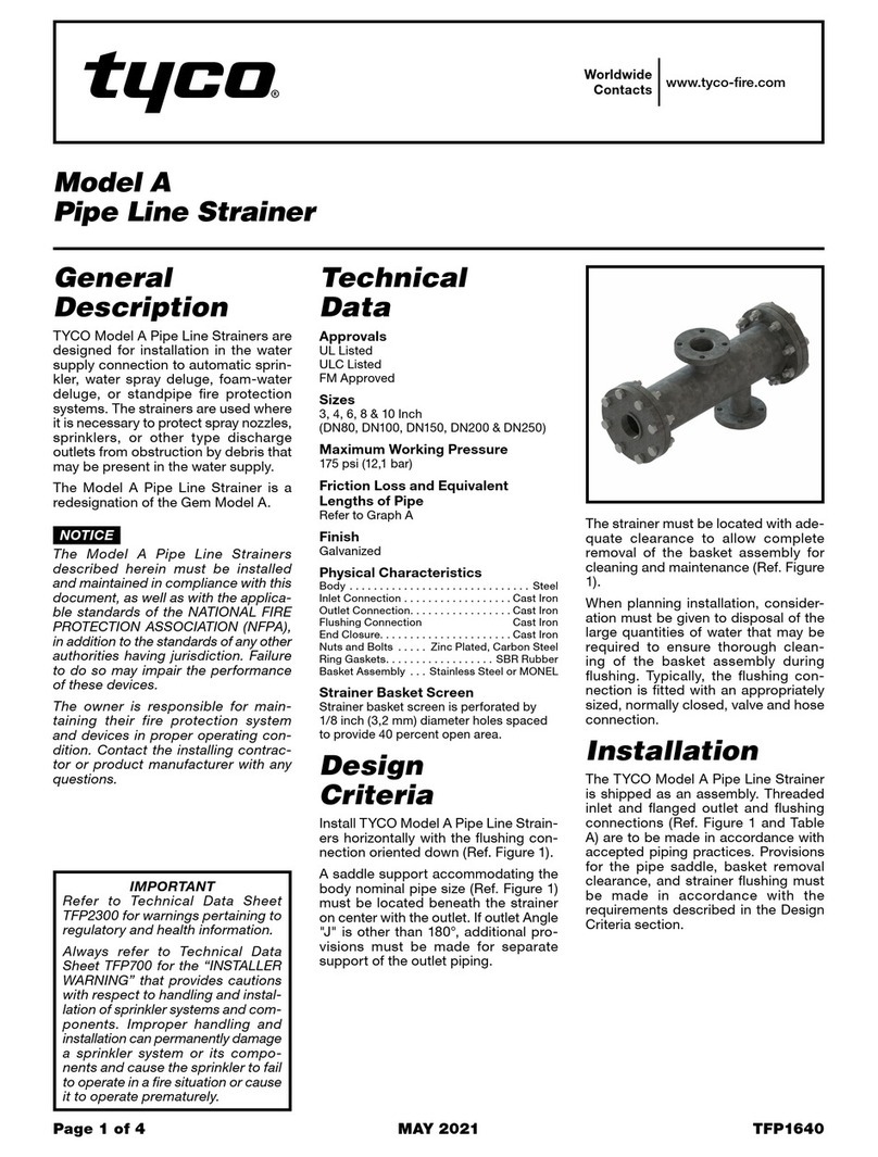
Other Tyco Industrial Equipment manuals

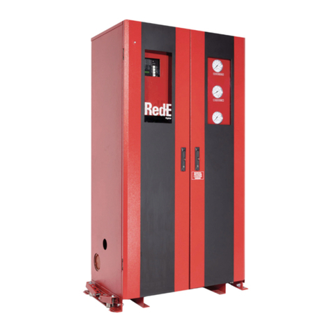
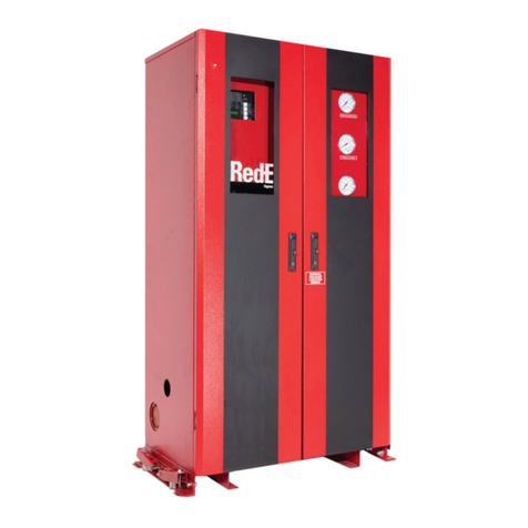
Tyco Deluge Red-E User manual

Tyco

Tyco Deluge Red-E User manual

Tyco AMD-3 User manual

Tyco

Tyco AMD-3 User manual

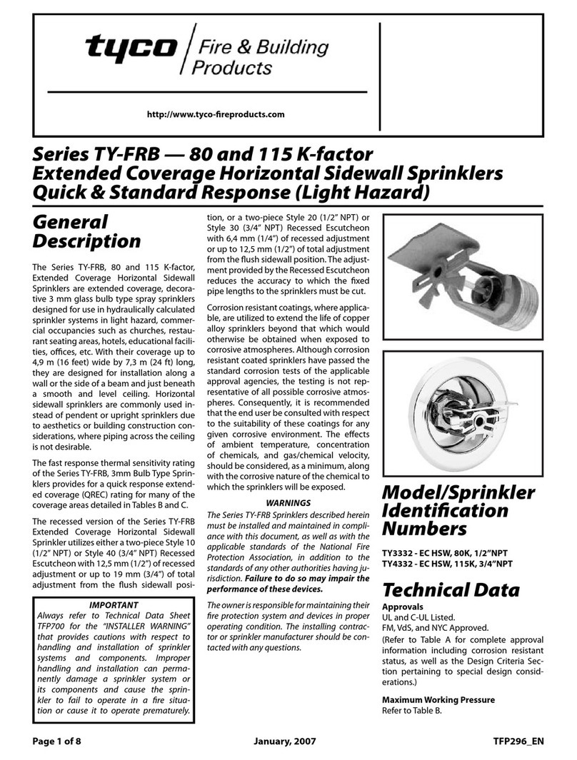
Tyco TY-FRB Series User manual

Tyco

Tyco TY-FRB Series User manual

Tyco A User manual

Tyco

Tyco A User manual

Tyco KANTECH KTES-FBOX Operating and maintenance manual

Tyco

Tyco KANTECH KTES-FBOX Operating and maintenance manual

Tyco HV User manual

Tyco

Tyco HV User manual

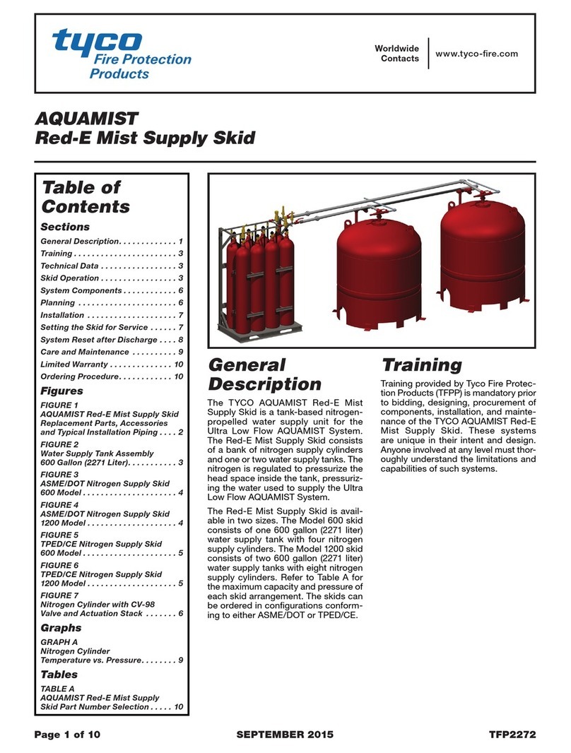
Tyco AQUAMIST Red-E Mist Supply Skid User manual

Tyco

Tyco AQUAMIST Red-E Mist Supply Skid User manual

Tyco DV-5A User manual

Tyco

Tyco DV-5A User manual

Tyco SHB1 User manual

Tyco

Tyco SHB1 User manual

Tyco 65 User manual

Tyco

Tyco 65 User manual

Tyco VIZOR User manual

Tyco

Tyco VIZOR User manual

Tyco TAV-D User manual

Tyco

Tyco TAV-D User manual

Tyco Rovalve S20 User manual

Tyco

Tyco Rovalve S20 User manual

Popular Industrial Equipment manuals by other brands

Ingersoll Typhoon HSM Operation manual

Ingersoll

Ingersoll Typhoon HSM Operation manual

Bernard LEB Instructions for start-up, storage and maintenance

Bernard

Bernard LEB Instructions for start-up, storage and maintenance

Siemens SIRIUS 3TF68 Series operating instructions

Siemens

Siemens SIRIUS 3TF68 Series operating instructions

hager ARM U Series instruction manual

hager

hager ARM U Series instruction manual

DROPSA MiQueL User Operating and Maintenance Manual

DROPSA

DROPSA MiQueL User Operating and Maintenance Manual

anitoa MQ6 Series instruction manual

anitoa

anitoa MQ6 Series instruction manual

Bredenoord VLM Series Complete Operation Manual

Bredenoord

Bredenoord VLM Series Complete Operation Manual

Eaton ADAPTORPADLOCK Series Instruction leaflet

Eaton

Eaton ADAPTORPADLOCK Series Instruction leaflet

IDEAL Exalt quick start guide

IDEAL

IDEAL Exalt quick start guide

Flow MACH 300 manual

Flow

Flow MACH 300 manual

BECKWITH ELECTRIC M-7651A D-PAC Instruction book

BECKWITH ELECTRIC

BECKWITH ELECTRIC M-7651A D-PAC Instruction book

Georg Fischer MULTI/JOINT 3000 Plus user manual

Georg Fischer

Georg Fischer MULTI/JOINT 3000 Plus user manual

YOKOGAWA AR-LP user manual

YOKOGAWA

YOKOGAWA AR-LP user manual

SUHNER MACHINING BEA 25 Technical document

SUHNER MACHINING

SUHNER MACHINING BEA 25 Technical document

Greiner Vibrograf Helmut Klein Magnomaster operating manual

Greiner Vibrograf

Greiner Vibrograf Helmut Klein Magnomaster operating manual

Pfeiffer Vacuum MPT 200 operating instructions

Pfeiffer Vacuum

Pfeiffer Vacuum MPT 200 operating instructions

IKA EUROSTAR 60 DIGITAL user guide

IKA

IKA EUROSTAR 60 DIGITAL user guide

Festo DGSL operating instructions

Festo

Festo DGSL operating instructions

manuals.online logo
manuals.online logoBrands
  • About & Mission
  • Contact us
  • Privacy Policy
  • Terms and Conditions

Copyright 2025 Manuals.Online. All Rights Reserved.