manuals.online logo
Brands
  1. Home
  2. •
  3. Brands
  4. •
  5. Tyco
  6. •
  7. Industrial Equipment
  8. •
  9. Tyco SHB1 User manual

Tyco SHB1 User manual

CPVC Hangers
Head Set
Model SHB1
Page 1 of 4 JANUARY 2021 TFP1920
Worldwide
Contacts
www.tyco-fire.com
IMPORTANT
Refer to Technical Data Sheet
TFP2300 for warnings pertaining to
regulatory and health information.
General
Description
The TYCO CPVC Hanger Head Set
Model SHB1 offers a time saving instal-
lation method for proper placement
of an automatic sprinkler before the
ceiling is installed.
The hanger head set is a re-designa-
tion for the Central Model SHB1 Hanger
Head Set.
The hanger head set in a side-mount
position, as shown in Figure 2, pro-
vides accurate vertical positioning of
the sprinkler thereby assuring a desir-
able uniform sprinkler deflector-to-ceil-
ing positioning of the sprinklers. Due to
the unique design of the Hanger Head
Set, “blocking” is not required to offset
the centerline of piping to accommo-
date the sprinkler escutcheon from the
side of the joist. With the fasteners pro-
vided, the hanger head set is intended
to be attached directly to the side of a
solid wood framing member or the side
of a structural composite wood joist of
minimum 3/8 in. thickness OSB (Ori-
ented Strand Board) web member or
equivalent.
Note: The TYCO CPVC Hanger Head
Set Model SHB1 is designed for use
with Johnson Controls “West Coast”
style Sprinkler Head Adapters.
For ordering information for the sprin-
kler head adapters, see the Ordering
Procedure section.
NOTICE
The TYCO CPVC Hanger Head Set
Model SHB1 described herein must
be installed and maintained in compli-
ance with this document and the appli-
cable standards of the NATIONAL FIRE
PROTECTION ASSOCIATION (NFPA),
in addition to the standards of any
authorities having jurisdiction. Failure
to do so may impair the performance
of these devices.
The owner is responsible for maintain-
ing their fire protection system and
devices in proper operating condition.
The installing contractor or sprinkler
manufacturer should be contacted with
any questions.
Technical
Data
Approvals
UL Listed for use with CPVC pipe*
*For hanger head set side-mount installa-
tions as shown in Figure 2 - to provide accu-
rate vertical positioning of a sprinkler.
Material
Galvanized aluminum, 20 gauge
Weight
0.26 lb (0,12 kg)
TFP1920
Page 2 of 4
Installation
The installation instructions for the
TYCO CPVC Hanger Head Set Model
SHB1 for different types of wood joist
are defined in the following sections:
• Hanger Head Set — Solid Wood
Joist
• Hanger Head Set — Composite
Wood Joist
NOTICE
The TYCO CPVC Hanger Head Set
Model SHB1 does not meet the UL
requirement for providing vertical
restraint that may result from a sprin-
kler activation. A number of hanger
techniques (not inclusive of the use
of a Hanger Head Set) as described
in Installation Handbook IH-1900 can
be used to provide vertical restraint.
Failure to provide vertical restraint may
result in vertical lift upon sprinkler acti-
vation and the inability of a sprinkler to
spray effectively in the event of a fire.
Installing sprinklers into the sprin-
kler adapter fittings prior to solvent
cementing the adapters to the drop is
unacceptable. Failure to allow sprin-
kler fitting joint to cure before install-
ing sprinklers may result in cement in
sprinkler waterway and inability of the
sprinkler to properly operate in the
event of a fire.
The hanger head set should not be
installed other than side-mount or
attached to anything other than the
side of a solid wood framing member
or structural composite wood joist, with
the fasteners provided, without prior
review and approval of the authority
having jurisdiction. Any other method
of installation may not comply with
NFPA or local requirements. If the
installer attaches the Hanger Head Set
to another type of structural member or
orients the Hanger Head Set in a posi-
tion other than side-mount, fasteners
and fastener methods shall comply
with applicable NFPA and local code
requirements.
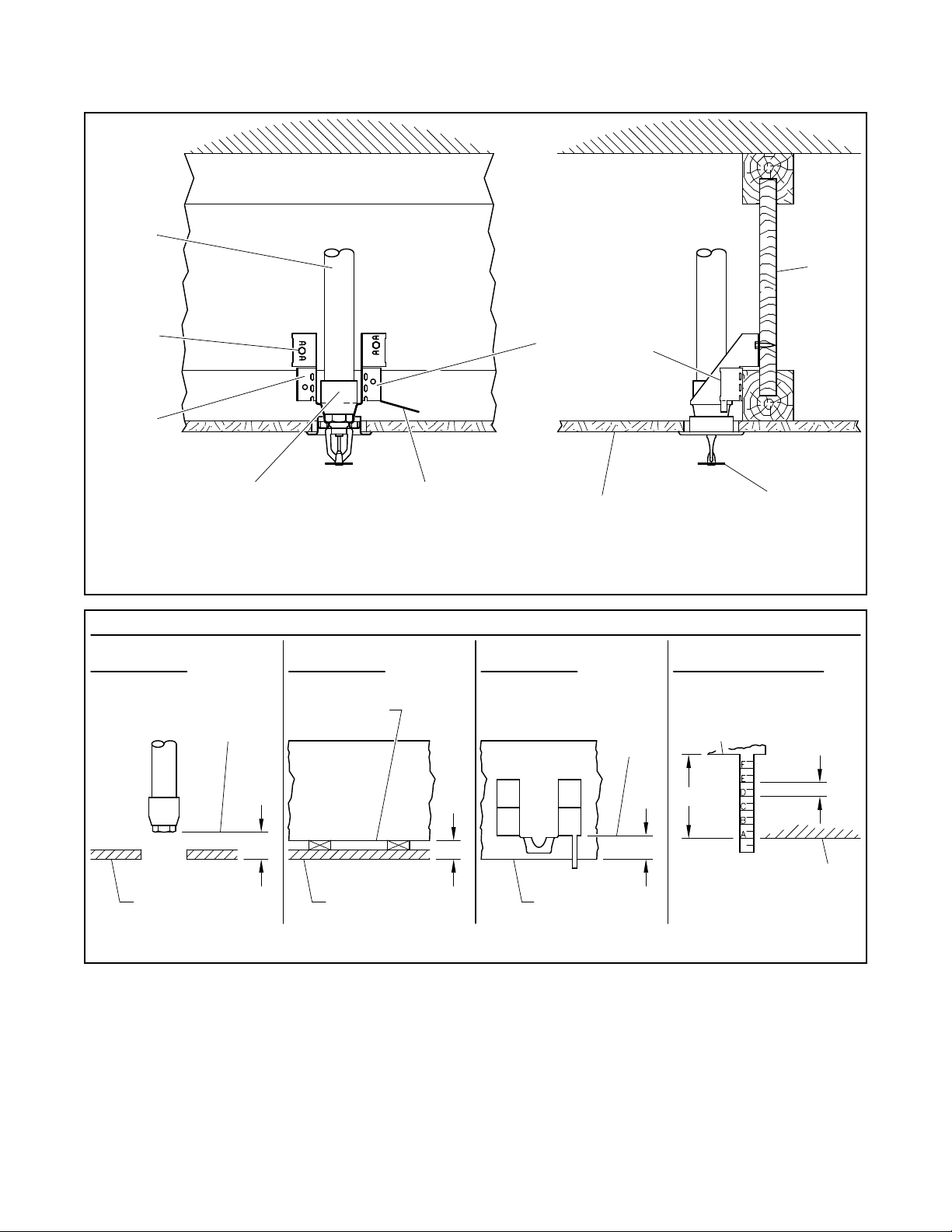
Hanger Head Set - Solid Wood Joist
Step 1. Position the hanger head set
against the vertical solid wood joist
surface (side-mount).
Step 2. Set the depth using the gradu-
ated markings on an offset gauge as
shown in Figure 3.
Step 3. Secure the hanger head set to
the wooden surface using the two #10
x 1 in. hex head lag screws.
Note: The screws are provided. See
Figure 1.
Step 4. Cut and install the CPVC sprin-
kler drop making sure the face of the
sprinkler head adapter is flush with the
inside of the head set cup.
Step 5. Insert the sprinkler inlet pipe
threads through the head set cup and
thread into the CPVC adapters using
the instructions provided in the tech-
nical data sheet for the sprinkler, and
Technical Data Sheet TFP700 for the
“INSTALLER WARNING”.
Hanger Head Set - Composite
Wood Joist
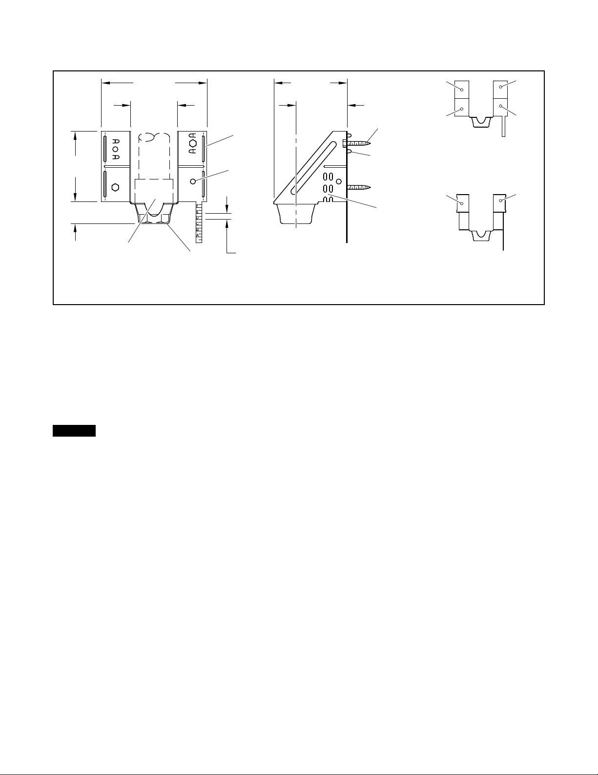
Step 1. Use a pliers to break off the
breakaway tabs as shown in Figure 4.
Step 2. Use the pliers to bend the lower
hanger mounting flange to a 90 degree
angle as shown in Figure 4.
Step 3. Position the hanger head set
against the composite wood joist web
member (side-mount).
Step 4. Set the depth using the grad-
uated markings of an offset gauge as
shown in Figure 3.
Step 5. Secure the hanger head set to
the wooden surface using the two #10
x 1 in. hex head lag screws.
Note: The screws are provided. See
Figure 1.
Step 6. Cut and install the CPVC sprin-
kler drop making sure the face of the
sprinkler head adapter is flush with the
inside of the head set cup.
Step 7. Insert the sprinkler inlet pipe
threads through the head set cup and
thread into CPVC adapters using the
instructions provided in the techni-
cal data sheet for the sprinkler, and
Technical Data Sheet TFP700 for the
“INSTALLER WARNING”.
3"
(76,2 mm)
1"
(25,4 mm)
3"
(76,2 mm)
2"
(50,8 mm)
2-3/16"
(55,6 mm)
BUILT-IN
OFFSET GAUGE
IN 1/4" (6,3 mm)
INCREMENTS
SCREW
HOLES
BREAK-
AWAY
TABS
4-1/2"
(114,3 mm)
LOCATING
TABS
#10 x 1"
HEX HEAD
LAG SCREW
(2 PROVIDED)
SPRINKLER HEAD
ADAPTER FLUSH WITH
INSIDE OF HEAD SET CUP
HEAD SET
CUP
1
3
2
4
1 2
ON SOLID WOOD JOISTS,
USE SCREW POSITIONS
1 + 2, 1 + 4, or 2 + 3
ON COMPOSITE WOOD JOISTS,
USE SCREW POSITIONS 1 + 2
LOWER
FLANGE
BEND
AREA
FIGURE 1
MODEL SHB1 HANGER HEAD SET
(NOMINAL DIMENSIONS)
TFP1920
Page 3 of 4
X + 1" - Y = Z
DETERMINE "X"
STEP 1
DETERMINE "Y"
STEP 2
CALCULATE "Z"
STEP 3
SPRINKLER
REFER TO
DATA SHEET
CONVERT "Z" TO GAUGE
STEP 4
BOTTOM OF JOIST
ALIGN "A" WITH
EQUALS 1-1/2",
EXAMPLE: IF "Z"
"X"
FACE OF
SPRINKLER
FITTING
MOUNTING
SURFACE
(CEILING)
"Y"
BOTTOM
OF JOIST
MOUNTING
SURFACE
(CEILING)
"Z"
BOTTOM
OF JOIST
BOTTOM
EDGE OF
HEAD SET
FLANGE
BOTTOM EDGE
OF HEAD SET
FLANGE
OFFSET
GAUGE IN
1/4" (6,3 mm)
INCREMENTS
BOTTOM
OF JOIST
1-1/2"
USE ONLY TFPP
80175W or 80176W
SPRINKLER HEAD
ADAPTER
CPVC
PIPE AND
FITTINGS
OFFSET GAUGE
BENT AWAY TO
CLEAR CEILING
MATERIAL
TYPICAL
RECESSED
RESIDENTIAL
SPRINKLER
TYPICAL
GYPSUM BOARD
CEILING
LOWER
HANGER MOUNTING
FLANGES BENT TO
SUIT COMPOSITE
WOOD JOIST
JOIST
USE
PROVIDED
MOUNTING
SCREWS
ONLY
(TYP.)
HEAD SET
HANGER
FIGURE 2
SIDE-MOUNT INSTALLATION OF HANGER HEAD SET
PROVIDING ACCURATE VERTICAL POSITIONING OF THE SPRINKLER
FIGURE 3
USE OF OFFSET GAUGE FOR HANGER HEAD SET
TFP1920
Page 4 of 4
NATIONAL FIRE PROTECTION ASSOCIATION and NFPA are registered trademarks of National Fire Protection Association;
1400 Pennbrook Parkway, Lansdale, PA 19446 | Telephone +1-215-362-0700
© 2021 Johnson Controls. All rights reserved. All specifications and other information shown were current as of document revision date and are subject to change without notice.
Care and
Maintenance
The owner is responsible for the inspec-
tion, testing, and maintenance of their
fire protection system and devices in
compliance with this document, as well
as with the applicable standards of the
NATIONAL FIRE PROTECTION ASSO-
CIATION such as NFPA 25, in addition
to the standards of any authority having
jurisdiction. The installing contractor or
product manufacturer should be con-
tacted relative to any questions.
Automatic sprinkler systems should be
inspected, tested, and maintained by a
qualified Inspection Service in accor-
dance with local requirements and/or
national codes.
Limited
Warranty
For warranty terms and conditions, visit
www.tyco-fire.com.
Ordering
Procedure
Contact your local distributor for avail-
ability. When placing an order, indicate
the full product name and Part Number
(P/N).
Hanger Head Set
Hanger Head Sets are provided in box
quantities of 100. Orders placed should
be for full box quantities.
Specify: Model SHB1 Hanger Head
Set, P/N HS2
Sprinkler Head Adapter
Specify: Johnson Control West Coast
style Sprinkler Head Adapter, size
(specify), P/N (specify):
3/4 in. x 1/2 in. NPT.. . . . . . . . . . . . . . . . 80175W
1 in. x 1/2 in. NPT. . . . . . . . . . . . . . . . . . 80176W
3/4 in. x 1/2 in. NPT.. . . . . . . . . . . . . . .80175RS2
1 in. x 1/2 in. NPT. . . . . . . . . . . . . . . . .80176RS2
BREAKAWAY TABS
MAY BE REMOVED
AT SCORING
USE CAUTION,
EXPOSED EDGES
MAY BE SHARP
FIRMLY
GRASP
FLANGE
AT BEND
AREA
LOWER
HANGER
MOUNTING
FLANGE
BEND
FLANGES TO
SUIT BOTTOM
CHORD OF
JOIST
OFFSET
GAUGE MAY BE
BENT AWAY TO
CLEAR CEILING
MATERIAL
FIGURE 4
MODIFICATIONS REQUIRED TO
INSTALL HANGER HEAD SET ON
COMPOSITE WOOD JOIST

Other Tyco Industrial Equipment manuals

Tyco TY-FRB Series User manual

Tyco

Tyco TY-FRB Series User manual

Tyco VIZOR User manual

Tyco

Tyco VIZOR User manual

Tyco AQUAMIST Red-E Mist Supply Skid User manual

Tyco

Tyco AQUAMIST Red-E Mist Supply Skid User manual

Tyco 65 User manual

Tyco

Tyco 65 User manual

Tyco HV User manual

Tyco

Tyco HV User manual

Tyco AMD-3 User manual

Tyco

Tyco AMD-3 User manual

Tyco DV-5A User manual

Tyco

Tyco DV-5A User manual

Tyco TAV-D User manual

Tyco

Tyco TAV-D User manual

Tyco KANTECH KTES-FBOX Operating and maintenance manual

Tyco

Tyco KANTECH KTES-FBOX Operating and maintenance manual

Tyco A User manual

Tyco

Tyco A User manual

Tyco GRINNELL F445 User manual

Tyco

Tyco GRINNELL F445 User manual

Tyco Deluge Red-E User manual

Tyco

Tyco Deluge Red-E User manual

Tyco Rovalve S20 User manual

Tyco

Tyco Rovalve S20 User manual

Popular Industrial Equipment manuals by other brands

Danfoss FT1390 Operator's manual

Danfoss

Danfoss FT1390 Operator's manual

Wilo Wilo-EMU FA+T-Motor Installation and operating instruction

Wilo

Wilo Wilo-EMU FA+T-Motor Installation and operating instruction

HERKULES OFC6 owner's manual

HERKULES

HERKULES OFC6 owner's manual

Siemens Sivacon S8 operating instructions

Siemens

Siemens Sivacon S8 operating instructions

BONFIGLIOLI 700C Series Installation and service manual

BONFIGLIOLI

BONFIGLIOLI 700C Series Installation and service manual

Grundfos CR Installation and operating instructions

Grundfos

Grundfos CR Installation and operating instructions

Nexen AIR CHAMP 4H30 user manual

Nexen

Nexen AIR CHAMP 4H30 user manual

Altronic GTI Bi-Fuel Installation & operating manual

Altronic

Altronic GTI Bi-Fuel Installation & operating manual

ALFRA AMTE250 Operation manual

ALFRA

ALFRA AMTE250 Operation manual

Valor TRD-54-T owner's manual

Valor

Valor TRD-54-T owner's manual

TCRS AC30TON Operating and service manual

TCRS

TCRS AC30TON Operating and service manual

Hoffmann eXess operating manual

Hoffmann

Hoffmann eXess operating manual

DOLD VARIMETER IMD RN 5897/020 Translation of the original instructions

DOLD

DOLD VARIMETER IMD RN 5897/020 Translation of the original instructions

CAB 4414 Series Assembly instructions

CAB

CAB 4414 Series Assembly instructions

Kobelt 7172 quick start

Kobelt

Kobelt 7172 quick start

Schmalz EVE-TR 4 - 8 DC operating instructions

Schmalz

Schmalz EVE-TR 4 - 8 DC operating instructions

ABB HT568476 Operation manual

ABB

ABB HT568476 Operation manual

TopGears ITG 125 Operation and maintenance manual

TopGears

TopGears ITG 125 Operation and maintenance manual

manuals.online logo
manuals.online logoBrands
  • About & Mission
  • Contact us
  • Privacy Policy
  • Terms and Conditions

Copyright 2025 Manuals.Online. All Rights Reserved.