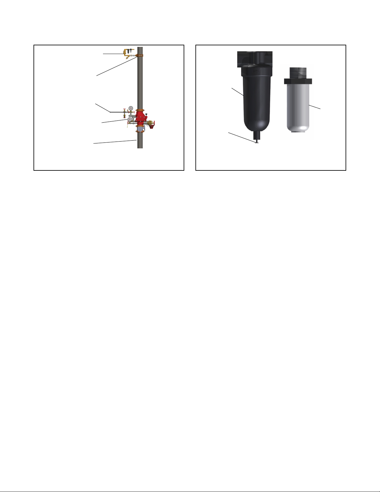
Tyco TAV-D User manual

Model TAV-D
Air Vent, Dry
Page 1 of 4 AUGUST 2022 TFP1262
Worldwide
Contacts
www.tyco-fire.com
IMPORTANT
Refer to Technical Data Sheet
TFP2300 for warnings pertaining to
regulatory and health information.
Scan the QR code or enter the URL
in a web browser to access the most
up-to-date electronic version of this
document. Data rates may apply.
docs.jci.com/tycore/tfp1262
General
Description
The TYCO Model TAV-D Air Vent, Dry,
provides oxygen venting in dry pipe
re sprinkler systems. As a re sprin-
kler system is lled with a continuous
supply of nitrogen gas from the TYCO
Nitrogen Generator, the air vent allows
oxygen rich gas to be vented from
the re sprinkler system. Over a short
period of time the air vent will almost
completely remove oxygen from the re
sprinkler system (< 2% oxygen).
The air vent must be installed as shown
on the engineering design documents.
If a location is not specied, install the
air vent on the re sprinkler system riser
on the system side of the main control
valve. The vent is also installed to
provide source gas when used in con-
junction with the TYCO TSGA SMART
Gas Analyzer.
The air vent is equipped with a levered
oat valve that allows oxygen to dis-
charge but prevents water from
leaking through the restricted venting
orice in the event that water enters
the re sprinkler system, as shown
in Figure 1. A backpressure regula-
tor is also included to prevent total
system depressurization from the vent
assembly.
The restricted venting orice allows
oxygen to be vented from the fire
sprinkler system at a controlled rate to
achieve a minimum nitrogen concentra-
tion of 98%. A special tting is provided
to receive 5/32 in. tubing when the vent
is used in conjunction with the TYCO
Model TSGA SMART Gas Analyzer.
There are two models of the TYCO Air
Vent, the TAV-D and the TSV-D. Both
units operate as described above while
the TSV-D SMART model includes an
electronic solenoid valve wired to a
control panel that automatically closes
the vent once the desired nitrogen con-
centration is reached. The control panel
is also equipped with a reset switch to
allow the venting process to restart
should oxygen be reintroduced into the
re sprinkler system. Refer to Technical
Data Sheet TFP1263 for complete infor-
mation on the TSV-D SMART Air Vent.
NOTICE
The TYCO Model TAV-D Air Vent, Dry,
described herein must be installed and
maintained in compliance with this
document, in addition to the standards
of any other authorities having jurisdic-
tion. Failure to do so may impair the
performance of the related devices.
The owner is responsible for main-
taining their fire protection system
and devices in proper operating con-
dition. Contact the installing contrac-
tor or product manufacturer with any
questions.
Technical
Data
Service Pressure
Up to 175 psig (12 bar)
System Connection
1 in. NPT Male
Temperature Range
40°F to 120°F (4.5°C to 49°C)
Dimensions
12.0 in. (W) x 4.65 in. (D) x 9.1 in. (H)
(305 mm (W) x 118 mm (D) X 231 mm (H))

TFP1262
Page 2 of 4
FIGURE 1
MODEL TAV-D AIR VENT DRY
AS SEM BLY
Operation
Step 1. Verify the vent assembly is
equipped with a restricted venting
orice downstream of the backpres-
sure regulator.
Note: If the vent assembly is not
equipped with a restricted venting
orifice, contact Johnson Controls Tech-
nical Services. The restricted venting
orifice must be installed before pro-
ceeding with the steps below.
Step 2. Determine the low air alarm
pressure and the turn-on pressure of
the nitrogen generator.
Step 3. Choose a pressure setting
for the backpressure regulator that
is 3 to 5 psig (0,2 to 0,3 bar) above
the low air alarm pressure but below
the turn-on pressure of the nitrogen
generator.
Step 4. Pull the knob out from the reg-
ulator to adjust the pressure setting.
Turn the knob clockwise to raise the
pressure, counter-clockwise to lower
the pressure.
Step 5. Close the ball valve and allow
the device to depressurize through
the restricted venting orice to the
pressure setting. Adjust the pressure
setting using the knob, then open the
ball valve to pressurize the device and
close the ball valve again to check the
pressure setting. Repeat the process
until the desired pressure setting is
achieved.
Note: This process can only be per-
formed when the fire sprinkler system
is at normal operating pressure.
Step 6. Push the knob back into the
regulator until it clicks into place.
Step 7. Once the TYCO Nitrogen Gen-
erator is commissioned, open the iso-
lation ball valve on the vent assembly.
The air vent is now open and actively
venting oxygen from the re sprin-
kler system. It should remain open
for approximately 14 days or until the
system nitrogen concentration reaches
98% or greater. Use a TYCO Model
THGA Handheld Gas Analyzer to verify
the gas concentration inside the re
sprinkler system.
Step 8. Close the isolation ball valve.
Failure to close the manual ball valve
after 14 days or once the re sprinkler
system nitrogen concentration reaches
98% will result in additional oxygen
corrosion damage to the system and
unnecessary run time of the air com-
pressor and nitrogen generator.
Step 9. If the sprinkler system actuates
or another event introduces oxygen
to the sprinkler system the manual
ball valve must be opened again for a
period of 14 days to vent oxygen from
the system.
RESTRICTED VENTING ORIFICEIN-LINE FILTER
MUFFLER
GAS SAMPLE PORT
BACKPRESSURE REGULATOR
CONNECTION TO
SPRINKLER SYSTEM
ISOLATION
BALL VALVE
QUICK CONNECT
“Y” STRAINER
WITH BALL VALVE
FLOAT
VALVE

TFP1262
Page 3 of 4
FIGURE 3
MODEL TAV-D AIR VENT DRY
IN-LINE FILTER
FIGURE 2
MODEL TAV-D AIR VENT DRY
INSTALLATION SCHEMATIC
Installation
The TYCO Model TAV-D Air Vent, Dry
must be installed in accordance with
this section.
Step 1. The Model TAV-D Air Vent is
equipped with a ball valve to be con-
nected to the re sprinkler riser. The
contractor must install a 1 in. outlet
(welded or mechanical) to connect the
vent assembly to the sprinkler system
on the system side of the main control
valve as shown in Figure 2. The ball
valve must remain in the closed posi-
tion until the TYCO Nitrogen Generator
is commissioned.
Step 2. Install the vent assem-
bly in a level position. The recom-
mended mounting height is between
5 ft to 10 ft (2 m to 3 m) above the n-
ished oor.
Note: Piping to the vent assembly
cannot be installed in a configura-
tion that would trap water and prevent
drainage to the sprinkler system; a
water trap impedes the ability of the
vent assembly to vent oxygen from the
fire sprinkler system.
Step 3. Inspection of the vent assem-
bly should be performed after installa-
tion and hydrostatic testing of the re
sprinkler system. Inspection should
be performed periodically thereaf-
ter in accordance with the applicable
NATIONAL FIRE PROTECTION ASSO-
CIATION (NFPA) codes and standards
and/or the authority having jurisdiction.
Note: Inspection must include the con-
dition of the in-line filter and checking
for blockage in the “Y” strainer and the
restricted venting orifice.
Care and
Maintenance
The TYCO Model TAV-D Air Vent, Dry
must be maintained and serviced in
accordance with this section.
Before closing a re protection system
main control valve for maintenance
work on the re protection system that
it controls, permission to shut down
the affected re protection systems
must rst be obtained from the proper
authorities. All personnel who may
be affected by this decision must be
notied.
Inspection, testing, and maintenance
must be performed in accordance
with the requirements of the NFPA, and
any impairment must be immediately
corrected.
The owner is responsible for the inspec-
tion, testing, and maintenance of their
re protection system and devices in
compliance with this document, as well
as with the applicable standards of any
authorities having jurisdiction. Contact
the installing contractor or product
manufacturer with any questions.
Inspection Instructions
Step 1. The Model TAV-D Air Vent must
be inspected annually at minimum.
While the isolation ball valve is in the
open position check for air/water leaks
and ensure the pressure gauge is dis-
playing normal system pressure.
Step 2. While the isolation ball valve is
in the closed position inspect the con-
dition of the inline lter and for block-
age in the “Y” strainer and restricted
venting orice. Twist the black Filter
Housing clockwise until it can be
removed to expose the lter element.
Step 3. Replace the In-Line Filter
element if a visual inspection reveals a
signicant collection of debris.
In-Line Filter Replacement
Instructions
Step 1. Close the isolation ball valve.
Step 2. Depressurize the housing by
pressing the pressure relief valve on
the bottom of the in-line lter housing
shown in Figure 3.
Step 3. Remove the lower section of
the In-Line Filter housing by turning the
lter housing counterclockwise.
Note: A rubber o-ring seal is located
between the upper and lower sections
of the filter housing.
Step 4. Remove the old lter by turning
the lter counterclockwise.
Step 5. Replace with a new lter, TYCO
Model TFLT Replacement Filter Kit.
The lter is secured to the housing by
turning the lter clockwise.
Note: Ensure the filter housing is
secured only finger/hand tight.
Step 6. Install the rubber o-ring/seal on
the lower section of the lter housing.
Step 7. Re-install the lter housing by
turning the lter housing clockwise.
Note: Ensure the filter housing is
secured only finger/hand tight.
Step 8. Open the isolation ball valve.
1 IN.
OUTLET
REQUIRED
NITROGEN
SUPPLY
DRY/PREACTION
SPRINKLER
VALVE
MODEL TAV-D
MANUAL VENT
RISER
FILTER
HOUSING
FILTER
PRESSURE
RELIEF
VALVE

TFP1262
Page 4 of 4
NATIONAL FIRE PROTECTION ASSOCIATION and NFPA are registered trademarks of National Fire Protection Association;
1467 Elmwood Avenue, Cranston, RI 02910 | Telephone +1-401-781-8220
© 2022 Johnson Controls. All rights reserved. All specifications and other information shown were current as of document revision date and are subject to change without notice.
Limited
Warranty
For warranty terms and conditions, visit
www.tyco-re.com.
Ordering
Procedure
Contact your local distributor for avail-
ability. When placing an order, indicate
the full product name and Part Number
(P/N).
Air Vent, Dry
Specify: Model TAV-D Air Vent, Dry,
P/N TAVD02
Note: Part number TAVD02 replaces
the legacy part number TAVD01.
Replacement Filter Kit
For a replacement lter for the Model
TAV-D Vent, Dry current P/N TAVD02:
Specify: Model TFLT Replacement
Filter Kit, P/N TVDFLT2
For a replacement lter for the Model
TAV-D Vent, Dry legacy P/N TAVD01:
Specify: Model TFLT Replacement
Filter Kit, P/N TVDFLT

TFP1262
Change History Appendix
Worldwide
Contacts
www.tyco-fire.com
1467 Elmwood Avenue, Cranston, RI 02910 | Telephone +1-401-781-8220
© 2022 Johnson Controls. All rights reserved. All specifications and other information shown were current as of document revision date and are subject to change without notice.
ISSUE DATE NOTES
08-22
Page 1, added QR code and URL to allow convenient access to electronic version from printed docu-
ment; Page 4, changed corporate address and telephone number to 1467 Elmwood Avenue, Cranston,
RI 02910 | Telephone +1-401-781-8220, formerly 1400 Pennbrook Parkway, Lansdale, PA 19446 | Tele-
phone +1-215-362-0700.
09-20 Updated part number to TAVD02, formerly TAVD01; Added Model TFLT Replacement Filter Kit, part
number TVDFLT2, for maintaining TAVD02 assembly.
11-19 Removed Electrical Connection sub-section from Technical Data section.
09-19 New Technical Data Sheet TFP1262 describes Model TAV-D Air Vent, Dry.
Table of contents
Other Tyco Industrial Equipment manuals