Tyco Rovalve S20 User manual

Rovalve S20
Installation and Maintenance Instructions
Tyco reserves the right to change the contents without notice ROVMC-6614-EN-0904
1. General information
The ROVALVE S20 knife gate valve is a UNIDIRECTIONAL (one-way shut-off) product.
Unidirectional valves have a preferred shut-off direction.
CAUTION
Care must be taken in valve installation with respect to direction of flow.
Unidirectional valves have the preferred direction of shut-off
indicated by the word "SEAT" cast into the valve body or the
word "SEAT" stamped on the upper right hand corner of the gate
on the seat side. A unidirectional valve is normally installed with
the seat side (preferred direction) downstream, with the line
pressure pushing the gate toward the seat.
CAUTION
The user is responsible for correct directional installation.
On select applications, including low pressure - dry solids applications, greater performance may
be realized by installing the S20 in the reverse flow position. Valves supplied with backing rings are
normally installed in a reverse flow orientation, with the seat side of the valve upstream. Contact
factory for details and additional recommendations.
Initial inspection:
1. Examine entire valve and report any damage or discrepancies immediately.
2. Accessories, if any, including solenoids, limit switches, positioners, etc., are tested for
functionality prior to shipment. Examine carefully for damage which may occur during shipment.
3. Operators: Standard manual handwheels may be shipped loose for field installation. It is
necessary to use a pipe wrench or large crescent wrench to properly tighten the handwheel
retaining nut. Be sure to fully tighten.
4. Packing assembly: The packing gland bolts should be checked and adjusted to obtain a first
time packing seal. Packing gland bolts and or nuts may become slightly loose when valve is
shipped. Field adjustment is expected and desired. Tighten each nut equally just enough to
stop any leakage. Overtightening may increase valve operating torque and shorten packing life.
Thank you for purchasing a ROVALVE S20
knife gate valve product from Tyco Flow
Control. With proper care it should provide
you a long service life.
www.tycoflowcontrol.com
Index
1. General information 1
2. Installation instructions 2
3. General maintenance 4
4. Spare parts 4
5. Instructions for repacking 5
6. Stem nut replacement
instructions 6
7. Suggested cylinder support when
cylinder is mounted horizontal 7
8. Instructions for converting a
MH to bevel gear operator 8
9. Recommended long term storage
procedure 9
Tables and figures
Table A: Maximum flange bolt torques 2
Table B: Knife gate valve dimensions,
per MSS-SP81 3
Table C: Valve dimensions 3
Table D: Packing sizes 5
Figure 1, Retaining nut assembly 1
Figure 2, Packing gland nuts 1
Figure 3, Blind-tapped holes 2
Figure 4, Flange bolts 2
Figure 5, Envelope dimensions 3
Figure 6, Inspection points 4
Figure 7, Spare parts-topworks 4
Figure 8, Spare parts-valve body 4
Figure 9, Repacking instructions 5
Figure 10, SM636 packing 5
Figure 11, Stem nut replacement
instructions 6
Figure 12, Pin-style lockouts 8
Figure 13, BG conversion 8 Figure 1 Figure 2
Assemble handwheel,
be sure and fully
tighten handwheel
retaining nut
Inspect and tighten packing
gland nuts to stop any
leakage.

Rovalve S20
Installation and Maintenance Instructions
Tyco reserves the right to change the contents without notice page 2
Table A maximum flange bolt torques
(Foot pounds)
Size Torque
5/8 55 +/-5
3/4 65 +/-5
7/8 110 +/-5
1 135 +/-5
1 1/8 150 +/-5
1 1/4 200 +/-5
1 1/2 250 +/-5
Figure 4
2. Installation instructions
Please take note of the specific installation tags provided with each valve.
1. The mating line flanges must be properly aligned prior to attempting installation. Slip on or weld
flanges can be used. Never try to make up for misaligned pipe flanges by the line bolting. Pipe
supports and/or expansion joints should be used to minimize pipe loads on valves.
2. Flange gaskets suitable for the application are required, sized to fit the raised face of the valve.
3. The ROVALVE S20 is suitable for use in either vertical or horizontal lines. If operator is other
than vertical, additional support may be required if valve is not handwheel operated.
4. The port flanges of the S20, 2" through 24" are drilled and tapped to ANSI B16.5/150, 30" and
36" are per MSS-SP44 with the face to face per MSS-SP81. The bolt holes in the chest or
upper flange area are blind tapped, (see Figure 3).
CAUTION
Care must be taken when installing studs or bolts in the tapped holes of the flange in the
valve chest area to prevent damage. See figure 4.
5. Cap screws or bolts that are too long can pinch the valve body, thereby forcing the body wall
into the gate, springing the gate out of line. Additional damage can occur on the gate face,
such as scoring or scratching of the gate. This type of damage normally requires the valve be
returned to our shop for repair.
6. To avoid damage, it is recommended that studs be used on all tapped bolt holes, especially the
upper chest holes. If cap screws are used, be sure that they do not enter beyond the depth of
the tapped hole when fully tightened.
Figure 3
Figure 4
Bolt holes in the chest or
upper flange area are blind
tapped
WrongRight
Stud with Nut
Cap Screw
Body can be deformed or fractured if flange
bolting is too long or overtorqued.

Rovalve S20
Installation and Maintenance Instructions
Tyco reserves the right to change the contents without notice page 3
Figure 5
Table B MSS-SP81 dimensions rovalve
Valve Flange Raised Bolt Circle No. bolt Thread Face to Flange
size diameter face diameter holes size / thread face thickness
2 6 3-5/8 4-3/4 4 5/8-11 NC 1-7/8 1/2
3 7-1/2 5 6 4 5/8 -11 NC 2 1/2
4 9 6-3/16 7-1/2 8 5/8 -11 NC 2 1/2
5 10 7-5/16 8-1/2 8 3/4 -10 NC 2-1/4 5/8
6 11 8-1/2 9-1/2 8 3/4 -10 NC 2-1/4 5/8
8 13-1/2 10-5/8 11-3/4 8 3/4- 10 NC 2-3/4 5/8
10 16 12-3/4 14-1/4 12 7/8 -9 NC 2-3/4 3/4
12 19 15 17 12 7/8 -9 NC 3 3/4
14 21 16-1/4 18-3/4 12 1 -8 NC 3 13/16
16 23-1/2 18-1/2 21-1/4 16 1 -8 NC 3-1/2 7/8
18 25 21 22-3/4 16 1 1/8-7 NC 3-1/2 15-/16
20 27-1/2 23 25 20 1 1/8-7 NC 4-1/2 1
24 32 27-1/4 29-1/2 20 1-1/4-7 NC 4-1/2 1
30 38-3/4 33-3/4 36 28 1-1/4-7 NC 4-5/8 1-1/8
36 46 40-1/4 42-3/4 32 1-1/2-6 NC 4-5/8 1-1/8
Table C valve dimensions
Valve size A B C D E F Weight
2 8 6 1-7/8 12 14-1/4 2-3/4 18
3 8 7-1/2 2 13-3/4 17 2-7/8 22
4 8 9 2 15-1/2 19-3/4 2-7/8 28
6 12 11 2-1/4 20-5/8 26-7/8 3-3/4 53
8 12 13-1/2 2-3/4 24-3/8 32-5/8 3-5/8 72
10 16 16 2-3/4 28-3/4 39 4-1/2 109
12 16 19 3 32-1/4 44-1/2 4-1/2 146
14 20 21 3 35-1/2 49 8 225
16 20 23-1/2 3-1/2 38-7/8 54-1/4 5-3/4 288
18 20 25 3-1/2 43 60-3/8 10 356
20 20 27-1/2 4-1/2 47 66-1/2 11-3/8 488
24 20 32 4-1/2 54-1/2 77-3/4 15-5/8 723
30 18 38-3/4 4-5/8 74-3/4 95-1/4 18 1303
36 18 46 4-5/8 87-3/4 113-7/8 12 1842
Note 1) These dimensions duplicate ANSI B16.5/150 flange drilling
Note 2) Flange thickness includes 1/16" raised face
Note 3) Through bolt flange drilling is bolt size plus 1/8".
Note: 30" and 36" are standard with bevel gear actuator, Dimension D is centerline to top of 18" diameter handwheel.

Rovalve S20
Installation and Maintenance Instructions
Tyco reserves the right to change the contents without notice page 4
4. Spare parts
1. The following spare parts are recommended:
Valves:
1- Set replacement packing
Cylinder Operator (if applicable):
1-Repair Kit
2. When ordering replacement parts for a ROVALVE product or cylinder operator, please include
valve or cylinder size and complete description including serial number with your request.
3. Additional replacement parts such as handwheels, stem nut assemblies, retainers, 4-Post Yoke,
stems, packing glands, and gates are available from factory. Again, please provide complete
description with serial number when ordering.
Note: Stem Nut assemblies include the #1 retaining nut and #2 stem nut.
Figure 6
Stem
Stem nut
(under retainer)
Grease
fitting
Packing
gland
Packing
Figure 8Figure 7
Body
Gate
Packing
gland
Handwheel
Stem Assy.
#1 Retaining nut
#2 Stem nut
Retainer
Retainer bolt
4-Post yoke leg
Packing
Grease fitting
3. General maintenance
We recommend that all ROVALVE products be inspected at least every 60 days. The following
points should be examined and corrected as required (see Figure 6):
1. Valve stems, extension stems, and stem nut: Look for excessive corrosion, galling or lack
of lubrication. If valve stem requires lubrication, utilize the grease fitting provided and pump
standard bearing grease through the yoke hub to lubricate the stem and stem nut assembly.
Additional lubrication may be applied directly onto stem or stem threads. (Use material which
meets ASTM 4950 GBLB.)
2. Packing gland: Check for leaks or worn packing. If leakage is occurring around the packing
gland, equally tighten the packing gland nuts, being careful not to overstress the bolting. If the
valve requires repacking, you may use any standard square braided packing as suitable for your
service. See additional instructions for repacking.
3. If possible stroke the valve through the full open and closed position to make sure it is
functioning properly.
Note 1: Stop all small leaks as soon as possible as considerable damage can be done to the
valve and the surrounding area if leakage is allowed to continue to grow.
Note 2: Replacement parts including handwheel and yoke assemblies, gates, packing glands,
seats and packing can be provided from our factory. If valve requires further repair,
please contact our office for an estimate of feasibility and cost of repair.

Tyco reserves the right to change the contents without notice page 5
Rovalve S20
Installation and Maintenance Instructions
5. Instruction for repacking Rovalve S20
Tools and materials required:
1. Open end wrenches or sockets to fit packing gland hex nuts and 4-Post yoke hex nuts.
2. Square braided packing suitable for application.
-ROVALVE standard packing is special TEFLON impregnated synthetic (AFPL).
3. Knife, to cut packing.
4. 3/8" x 2" flat bar approximately 2' long with rounded end.
5. Tool with radius end to fit inside of packing box.
CAUTION
Follow required safety procedure and policies. Assure line is not pressurized before loosening
packing and removing valve. Use proper lifting and support techniques when moving valve
and or valve subassemblies.
Prepare Valve
1. Relieve pressure on valve or remove valve.
2. Close the valve.
3. Disconnect the gate lifter.
4. Raise stem or rod to the fully raised (open) position, providing clearance, or if desired, the
entire actuator assembly may be pulled up and away from valve.
a) After step 3, remove top plate hex nuts and washers from 4-Post yoke.
b) Pull valve stem and entire actuator assembly, excluding 4-Post yoke up and away from
valve, set aside.
6. Remove packing gland hex nuts, packing gland, and old packing.
Installation of New Packing
If valve is equipped with SM636 packing, see note 2 before starting.
1. Cut packing to exact length for each row (See Table D). Starting on either side of the gate
install the packing all-around the gate one row at a time.
2. Tamp packing into packing box, even and flat using flat bar or other suitable tool.
3. Add next row, alternating sides of the gate where the ends of the packing meet against each
other. (Ends of packing must not line up. If they do premature leakage could occur.) Complete
by adding the number of rows required.
4. Reassemble packing gland to valve by sliding it down gate, aligning bolt holes with gland
studs.
5. Tighten packing gland until the top row of packing is slightly compressed.
6. Reassemble the actuator assembly, attach lifter to gate.
7. Slowly charge line, stop when packing leak is evident or until normal pressure is reached.
8. Retighten packing gland bolts only enough to stop the leakage, do not overstress the bolting.
9. If normal pressure has not been achieved, continue to add pressure and adjust packing gland
until normal pressure has been reached.
10. Check gland bolts and snug all packing gland nuts.
Note 1: Important, do not tighten packing gland bolts any more than required to stop packing
gland leaks after line pressure is applied.
Note 2: SM636 packing is triangular in shape, 1/2" (equilateral) on a side and about 2-1/2" long. It
can be broken into pieces to conform to the shape of the packing box. Install one (or two)
row(s) of Self Mold #636 as appropriate for the size valve. See Figure 2. Make sure that
all voids are filled.
Note 3: High-temperature packing may not reach full pliability until normal temperature is
achieved. Packing may require readjustment as temperature changes.
Figure 9
Figure 10
Valves with SM636 packing
Body
Gate
Packing
gland
Packing
Table D Packing Sizes
Valve Number Cross Cut
Size of Rows Section Length
2 3 3/8 6 3/8
3 3 3/8 8 3/8
4 3 3/8 10 3/8
6 4 3/8 14 3/4
8 5 3/8 19 1/4
10 4 3/8 23 3/4
12 4 3/8 28 7/8
14 4 1/2 27 1/4
16 4 1/2 35
18 4 1/2 38 5/8
20 4 1/2 42 5/8
24 4 5/8 51 1/2
30 4 5/8 64 1/2
36 4 5/8 77

Tyco reserves the right to change the contents without notice page 6
Rovalve S20
Installation and Maintenance Instructions
6. Stem nut replacement instructions
Replacement of the stem nut assembly on a Rovalve S20 is very simple. It is not necessary, or
desired, to remove the yoke assembly to replace the nut.
Tools required:
1. Pipe wrench or large crescent wrench
2. Appropriate size open end wrench for retainer bolts
CAUTION
Follow required safety procedure and policies. Use proper lifting and support techniques
when moving valve and or valve subassemblies.
Prepare the valve:
1. Line should be depressurized or gate secured prior to disassembly. If valve is equipped with
pin-style lockouts (see figure 12) gate can be locked in the open or closed position using the
lock pin. If pin-style lockouts are not present, the gate must be held in place to prevent
unwanted movement. These precautions are necessary to keep the gate from moving.
Disassembly:
1. Using pipe wrench or crescent wrench, remove handwheel retaining nut from stem nut.
2. Remove handwheel.
3. Remove (2) or (4) retainer bolts.
4. Pull retainer off
5. Rotate old stem nut until free from stem.
Reassembly:
1. Rotate new stem nut until it bottoms against top plate.
2. Place retainer over stem nut, lining up the bolt holes.
3. Replace retainer bolts and nuts, tighten completely.
4. Place handwheel over stem nut, aligning the hex.
5. Attach new handwheel retainer nut, using pipe wrench or crescent wrench, tighten completely.
6. Grease as required using grease fitting.
Figure 11
Handwheel
Stem Assy.
#1 Retaining nut
#2 Stem nut
Retainer
Retainer bolt
Yoke post (qty 4)
Grease fitting

Rovalve S20
Installation and Maintenance Instructions
Tyco reserves the right to change the contents without notice page 7
7. Suggested cylinder support methods when cylinder is mounted in horizontal or
off-vertical orientation
Cylinders require additional support when mounted in the other than vertical position. Failure to do
so could lead to premature failure of cylinder and/or valve. The following figures are suggestions;
specific details will have to be determined by customer so support best suits surrounding area.
It is important that the cylinder/gate alignment be maintained during valve operation. Supports
should be designed to maintain alignment and support bulk of cylinder weight.
CAUTION
Tie-rod mounted supports are not recommended on spring-style cylinder actuators.
Installation A
Installation B
Installation C
Appropriate tie-in capable of
supporting load Turnbuckle for
adjustment
Saddle-style
hanger
Appropriate tie-in capable of
supporting load
Saddle-style support
Appropriate tie-in capable of
supporting load.
Turnbuckle for
adjustment
Alternate head-support,
saddle style preferred

Rovalve S20
Installation and Maintenance Instructions
Tyco reserves the right to change the contents without notice page 8
8. Converting MH to BG valves
Bevel gear conversion for the Rovalve S20 is very simple. It is not necessary to remove the 4-Post
yoke assembly. Conversion kits include bevel gear operator with integral thrust style stem nut,
conversion mounting plate, appropriate bolts, and handwheel or drive nut as required. Existing
stem and yoke posts will be reused. If stem or yoke posts require replacement, contact the
factory.
CAUTION
Follow required safety procedure and policies. Assure line is not pressurized or gate has been
secured to prevent unwanted movement before disassembly. Use proper lifting and support
techniques when moving valve and or valve subassemblies.
Tools required:
1. Pipe wrench or large crescent wrench
2. Appropriate size open end wrenches or sockets
Prepare the valve:
1. Line should be depressurized or gate secured prior to disassembly. If valve is equipped with
pin-style lockouts (see figure 12) gate can be locked in the open or closed position using the
lock pin. If pin-style lockouts are not present, the gate must be held in place to prevent
unwanted movement. These precautions are necessary to keep the gate from moving.
Disassembly:
1. Using pipe wrench or crescent wrench, remove handwheel retaining nut from stem nut.
2. Remove handwheel.
3. Remove (2) or (4) retainer bolts.
4. Pull retainer off
5. Rotate old stem nut until free from stem.
6. Remove nuts from the 4-post yoke legs.
7. Pull existing top plate up and away from valve.
Reassembly:
1. The conversion kit will be shipped with the thrust stem nut installed within the bevel gear.
2. Place the adapter plate over the 4-Post yoke legs aligning the holes.
3. Attach nuts onto 4-post yoke legs securing the top plate into position.
4. Slip the bevel gear over the stem nut, engaging the threads. Rotate the handwheel which will in
turn rotate the thrust stem nut down the stem, bringing the bevel gear into proper position,
aligning the bolt holes.
5. Bolt the bevel gear to the adapter plate. Do not overstress bolting.
6. Stroke the valve from full open to full closed making sure all parts are aligned and working
properly. Check bolts for tightness, the gate and operator assembly should stay snug with the
valve body.
7. If binding or off-center movement of gate is evident, loosen yoke bolts, stroke gate up and
down a few times, retighten yoke bolts.
Figure 12
Figure 13
L1: Pin style, both open and closed
lockpositions
L2: Pin style, open position only
L3: Pin style, closed position only.
L6: Case hardened pin for use on L1,
L2 or L3
BG bevel gear
actuator
open
closed
closed
open
pin
Thrust-style stemnut
included in BG
BG mount plate
BG mount bolts
4-Post yoke leg
Stem

Rovalve S20
Installation and Maintenance Instructions
Tyco reserves the right to change the contents without notice page 9
9. Recommended long term storage procedure
The following are the factory's recommendations for storage procedures to retain maximum
product integrity during long term storage of 1 to 5 years.
Handwheel or bevel gear operated valves
A. Storage facility: The preferred storage
location is a clean, dry protected
warehouse. If valves are to be stored
outside, precautions should be taken to
keep valves clean and dry. Standard
packaging materials provided in valve
shipment can not be considered sufficient
for outdoor storage.
B. Equipment orientation: Valves may be
stored in the vertical or horizontal position.
C. Preparation for storage: Valves may be
stored as shipped, provided the above
Storage Facility and Equipment Orientation
instructions above are followed. If valve
packaging is altered or removed for
receiving inspection, repackage valve as
originally received.
D. Storage inspection: Visual inspection shall
be performed on a semiannual basis and
results recorded. Inspection as a minimum
shall include reviewing the following:
Packaging
Flange Covers
Dryness
Cleanliness
E. Maintenance: Maintenance shall consist of
correcting deficiencies noted during
inspection. All maintenance shall be
recorded. Contact factory prior to
performing any maintenance if valve is still
covered under warranty.
Cylinder operated valves
A. Storage facility: The preferred storage
location is a clean, dry protected
warehouse. If valves are to be stored
outside, precautions should be taken to
keep valves clean and dry. Standard
packaging materials provided in valve
shipment can not be considered sufficient
for outdoor storage.
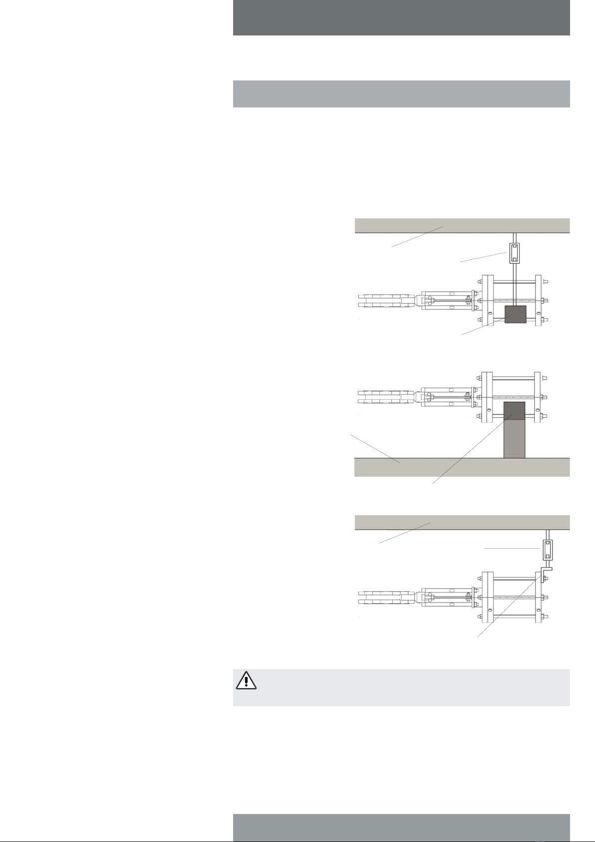
B. Equipment orientation: The preferred
orientation for optimum protection is with
the valve fully opened and the cylinder in
the vertical position. This position gives the
best support to the cylinder rod and helps
reduces the chance of a "flat spot"
developing on the cylinder seals. An
acceptable alternate position for valves
with cylinder diameters of less than 6" is
with the cylinder in the horizontal position.
C. Preparation for storage: Valves may be
stored as shipped, provided the above
Storage Facility and Equipment Orientation
instructions above are followed. If valve
packaging is altered or removed for
receiving inspection, repackage valve as
originally received.
D. Cylinder storage
These cylinder storage instructions are not
intended to replace the instructions of the
specific cylinder manufacturer and are to
be used as a guide only. If specific
instructions are required, please contact
our office.
For storage of up to 3 years; Squirt a high
quality grade of hydraulic oil or synthetic
lubricant into the cylinder ports and operate
cylinder 6-12 times on a yearly basis.
For storage 3-5 years; lubricate as above.
Additionally, extend cylinder rod until the
valve is fully closed. Coat cylinder rod with
high quality heavy grease or synthetic
lubricant. Retract cylinder rod until valve is
fully open, drawing lubricant into rod end of
cylinder. Securely plug cylinder ports with
pipe plugs, if cylinder is not pre-piped to
control accessories. If cylinder is prepiped
to accessories, plug all input and output
ports of accessories.
E. Storage inspection: Visual inspection shall
be performed on a semiannual basis and
results recorded. Inspection as a minimum
shall include reviewing the following:
Packaging
Flange Covers
Dryness
Cleanliness
F. Maintenance: Maintenance shall consist of
correcting deficiencies noted during
inspection. All maintenance shall be
recorded. Contact factory prior to
performing any maintenance if valve is still
covered under warranty.
Table of contents
Other Tyco Industrial Equipment manuals

Tyco
Tyco A User manual

Tyco
Tyco 65 User manual

Tyco
Tyco AQUAMIST Red-E Mist Supply Skid User manual

Tyco
Tyco Deluge Red-E User manual

Tyco
Tyco HV User manual

Tyco
Tyco KANTECH KTES-FBOX Operating and maintenance manual

Tyco
Tyco SHB1 User manual

Tyco
Tyco TAV-D User manual

Tyco
Tyco VIZOR User manual

Tyco
Tyco DV-5A User manual