TFP320
Page 4 of 8
Storage Type NFPA
Open Frame (that is, no solid shelves) Single, Double,
Multiple-Row, or Portable Rack Storage of Class I-IV
and Group A or B Plastics
Refer to NFPA 13, Chapters 16 and 17.
Solid Pile or Palletized Storage of Class I-IV and
Group A or B Plastics Refer to NFPA 13, Chapters 14 and 15.
Idle Pallet Storage Refer to NFPA 13, Chapter 12.
Rubber Tire Storage Refer to NFPA 13, Chapter 18.
Rolled Paper Storage Refer to NFPA 13, Chapter 19.
Flammable Liquid Storage Refer to NFPA 30.
Aerosol Storage Refer to 30B.
TABLE A
MODEL ESFR-17 DRY TYPE PENDENT SPRINKLERS
COMMODITY SELECTION AND DESIGN CRITERIA OVERVIEW
Installation
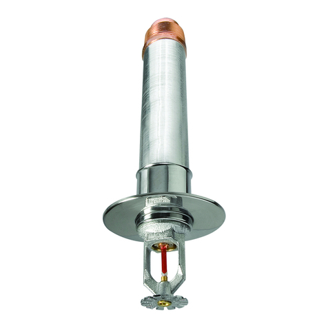
The TYCO Model ESFR-17 Dry Type
Pendent Sprinklers (TY7229) must
be installed in accordance with this
section.
General Instructions
Avoid damage to the fusible Link
Assembly during installation by using
only the Casing to handle the sprinkler
(that is, do not apply pressure to the
fusible Link Assembly), and by using
the appropriate sprinkler wrench.
Failure to do so can lead to an
unstable link assembly and premature
activation of the sprinkler. Damaged
sprinklers must be replaced.
Model ESFR-17 Dry Type Sprinklers
must only be installed in ttings/con-
nections that meet the requirements
of the Design Criteria section. Refer
to the Design Criteria section for other
important requirements regarding
piping design, exposure length, and
the sealing of the clearance space
around the sprinkler casing.
If a sprinkler using a threaded connec-
tion (vs. grooved connection) requires
replacement, remove the sprinkler
using only the W-Type 26 Sprinkler
Wrench. Fully engage the wrench
on the Inlet Wrench Hex (Figure
2). Replace with the new sprinkler
following the installation instructions
in this section.
Threaded Connection Instructions
A leak-tight 1-1/4 inch NPT sprinkler
joint should be obtained by applying a
minimum-to-maximum torque of 45 to
65 ft.-lbs. (61 to 88 Nm). Higher levels
of torque can distort the sprinkler inlet
with consequent leakage or impair-
ment of the sprinkler.
Step 1. Apply a non-hardening pipe-
thread sealant such as TEFLON to the
Male 1-1/4 inch NPT Inlet threads.
Step 2. Install the Model ESFR-17 Dry
Type Pendent Sprinkler in the pendent
position (Figure 3) by carefully raising
the pendent sprinkler through the
clearance hole. The deector of the
pendent sprinkler is to be parallel to
the ceiling.
Step 3. Wrench-tighten the Model
ESFR-17 Dry Type Sprinkler using
only the W-Type 26 Sprinkler Wrench
(Figure 2) and by fully engaging the
wrench on the inlet wrench hex (Figure
2). For reference, the FRAME ARMS
marking can be used to align with the
frame arms with the System Pipe as
shown in Figure 5.
Step 4. After installation, inspect the
Link Assembly of each Model ESFR-17
Dry Type Sprinkler for damage. In par-
ticular, verify that the Link Assembly
and Hook are positioned as illustrated
in Figure 1, and that the Link Assembly
is not bent, creased, or forced out of
normal position in any way. Replace
damaged sprinklers.
Step 5. Install the Insulation Rings
of the Insulating Seal Assemblies by
slipping the Insulation Rings around
the sprinkler casing as shown in
Figure 6. Place the Inserts over
the Insulation Rings by sliding the
Inserts around the casing. Place the
Housings over the Inserts and Insu-
lation Rings ensuring that the slot on
the Housings are 180 degrees to the
Inserts slot. Ensure that the Insulating
Seal Assemblies are snug against the
refrigerated storage ceiling. Secure
the Insulating Seal Assemblies to the
ceiling using two self-tapping screws
per assembly.
Grooved Connection Instructions
The following instructions are based
on using the 2 Inch Figure 705
Grooved Flexible Coupling or the
2 Inch Figure 577 Grooved Rigid
Coupling.
Step 1. Inspect the exterior groove
and the end connection of the
mating grooved connection and
sprinkler to verify all burrs, loose
debris, dirt, chips, paint and other
foreign materials such as grease are
removed. Sealing surfaces must be
free from sharp edges, projections,
indentations, and/or other defects.
Step 2. Verify that the coupling and
gasket grade are correct for the ap-
plication intended. Refer to Technical
Data Sheet TFP1895 for additional
gasket information. The sealing edges
and the outer surfaces of the gasket
should be covered with a ne layer
of lubricant. To prevent deteriora-
tion of the gasket material, a silicone
lubricant should be used to prevent
freezing of the lubricant.
Step 3. Install the Model ESFR-17 Dry
Type Pendent Sprinkler in the pendent
position (Figures 4 and 7) by carefully
raising the pendent sprinkler through
the clearance hole. The deector of
the pendent sprinkler is to be parallel
to the ceiling. Also, ensure that the
“FRAME ARMS” markings on the
sprinkler casing are aligned with the
System Pipe. (See Figure 5).
Step 4. Install the gasket by placing it
over the sealing portion of the grooved
inlet connection so that the gasket lip
does not extend beyond the end of
the groove sealing surface. Bring end
of the grooved inlet together with end
of grooved tting ensuring vertical
and horizontal alignment. Slide the
gasket over both sealing surfaces.
