Design
Criteria
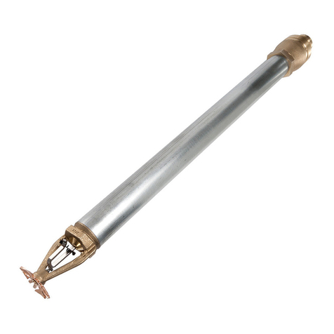
The TYCO Series LFII Dry-Type Resi-
dential Recessed Pendent Sprinklers
(TY2235) are UL Listed for installation
in accordance with the criteria listed in
this section.
When conditions exist that are outside
the scope of the criteria provided in this
section, refer to the technical data sheet
entitled Residential Sprinkler Design
Guide (TFP490) for the manufacturer’s
recommendations that may be acceptable
to the local authority having jurisdiction.
This section describes the following
design characteristics:
• System Types
• Water Delivery
• Hydraulic Design
• Obstruction to Water Distribution
• Operational Sensitivity
• Sprinkler Spacing
• Sprinkler Fitting
• Prevention of Branch Line Freezing
System Types
Wet pipe, dry pipe, and preaction sys-
tems may be utilized.
Water Delivery
For dry pipe and preaction systems, water
delivery to the most remote sprinkler for
a residential hazard shall not exceed 15
seconds as dened in Section 8.3.4.3 of
the 2010 edition of NFPA 13D or Section
7.2.3.6.3 of the 2010 edition of NFPA 13.
Using the TYCO SPRINKFDT Water
Delivery Calculation Program can help
determine whether required delivery
times will likely be achieved prior to
performing the actual installation.
As an alternative to using a UL Listed
water delivery calculation program and
method, as referenced in NFPA 13D
or NFPA 13, using an inspector's test
connection is required to provide ow
equivalent to the smallest orice sprin-
kler, wherein the test orice is located
on the end of the pipe supplying the
most remote sprinkler.
Hydraulic Design
Table A lists the minimum required sprin-
kler ow rate for systems designed to
NFPA 13D or NFPA 13R as a function
of temperature rating and the maximum
allowable coverage areas. The sprinkler
ow rate is the minimum required dis-
charge from each of the total number
of “design sprinklers,” as specied in
NFPA 13D or NFPA 13R.
For systems designed to NFPA 13, the
number of required design sprinklers is
the four most hydraulically demanding
sprinklers. The minimum required dis-
charge from each of the four sprinklers
is the greater of the following:
•
ow rates listed in Table A for NFPA
13D and 13R as a function of tempera-
ture rating and the maximum allowable
coverage area.
•
minimum discharge of 0.1 GPM/sq.
ft. over the design area comprised of
the four most hydraulically demand-
ing sprinklers for the actual coverage
areas protected by four sprinklers.
Examples of sprinkler designs follow:
•
Example 1 — Protection is planned for
a corridor that is 8 feet wide. Conse-
quently, the actual coverage area un-
der consideration is 8 ft. x 20 ft. Using
the Series LFII Dry-Type Residential
Sprinkler, the ow rate listed in Table
A for a 20 ft. x 20 ft. coverage area is
21 GPM. However, based on a mini-
mum discharge of 0.1 GPM/sq. ft., the
expected ow rate is 16 GPM (8 ft. x
20 ft = 160 sq.ft.). For this example, a
minimum ow rate of 21 GPM for this
sprinkler design is required.
•
Example 2 — Protection is planned
for a long, narrow room that is 12 feet
wide. Consequently, the actual cover-
age area under consideration is 12 ft.
x 20 ft. Using the Series LFII Dry-Type
Residential Sprinkler, the ow rate listed
in Table A for a 20 ft. x 20 ft. coverage
area is 21 GPM. However, based on
a minimum discharge of 0.1 GPM/sq.
ft., the expected ow rate is 24 GPM
(12 ft. x 20 ft = 240 sq.ft.). For this ex-
ample, a minimum ow rate of 24 GPM
for this sprinkler design is required.
Obstruction to Water
Distribution
Sprinklers are to be located in accordance
with the obstruction rules of NFPA 13D,
13R, and 13 as applicable for residential
sprinklers as well as with the obstruc-
tion criteria described within the TYCO
technical data sheet TFP490.
Operational Sensitivity
The sprinkler must be located relative
to the mounting surface as shown in
Figure 3.
Sprinkler Spacing
The minimum spacing between sprinklers
is 8 feet (2,4 m). The maximum spacing
between sprinklers cannot exceed the
length of the hydraulically-calculated
coverage area (refer to Table A); for
example, a maximum of 12 feet for a 12
ft. x 12 ft. coverage area or 20 feet for a
20 ft. x 20 ft. coverage area.
Sprinkler Fittings
Install the 1-inch NPT Series LFII Dry-
Type Residential Recessed Pendent
Sprinklers in the 1-inch NPT outlet or
run of one of the following ttings:
•
malleable or ductile iron threaded tee
ttings that meet the dimensional re-
quirements of ANSI B16.3 (Class 150).
•
cast iron threaded tee ttings that
meet the dimensional requirements
of ANSI B16.4 (Class 125).
For dry pipe systems, only use the side
outlet of maximum 2-1/2 inch size reduc-
ing tees when locating the Series LFII
Dry-Type Residential Recessed Pendent
Sprinklers directly below the branch line.
Otherwise, use the conguration shown
in Figure 6 to assure complete drainage
from above the Series LFII Sprinklers
and the branch line.
Do not install the Series LFII Dry-Type
Residential Recessed Pendent Sprin-
klers into elbow ttings. The Inlet of
the sprinkler can contact the interior
of the elbow, potentially damaging the
Inlet seal.
Typically, the end sprinkler tting on
a branch line is plugged as shown in
Figure 6.
The Series LFII Dry-Type Sprinklers can
also be installed in the 1-inch NPT outlet
of a GRINNELL Figure 730 Mechanical
Tee. However, the use of the Figure 730
for this arrangement is limited to wet
pipe systems.
Only use the conguration in Figure 4
where the sprinkler tting and water-
lled pipe above the sprinkler tting
are not subject to freezing and where
the length of the Series LFII Sprinkler
has the minimum exposure length per
Figure 6. Refer to the Exposure Length
section and Table B.
For wet pipe system installations of
the 1-inch NPT Series LFII Dry-Type
Residential Recessed Pendent Sprinklers
connected to CPVC piping, use only the
following TYCO CPVC ttings:
•
1” x 1” x 1” NPT Sprinkler Head Adapter
Tee (P/N 80249)
•
1” x 1” NPT Female Adapter (P/N 80145)
For residential dry pipe systems subject
to freezing, use the of 1” x 1” x 1” NPT
CPVC Sprinkler Head Adapter Tee (P/N
80259).
TFP460
Page 4 of 8
