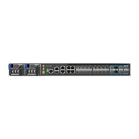
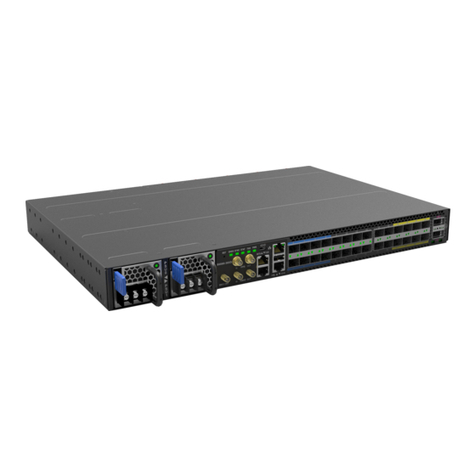
UfiSpace S9501-18SMT Manual

S9501-18SMT
Disaggregated
Cell Site Gateway
Hardware Installation Guide
R1.0

S9501-18SMT Hardware Installation Guide | i
Table of Contents
1 Overview.......................................................................................1
2 Preparaon ...................................................................................2
2.1 Installaon Tools..........................................................................................2
2.2 Installaon Environment Requirements......................................................3
2.3 Preparaon Check List .................................................................................4
3 Package Contents ..........................................................................5
3.1 Accessory List ..............................................................................................5
3.2 Component Physical Informaon ................................................................6
4 IdenfyingYourSystem .................................................................7
4.1 S9501-18SMT DC Version Overview ...........................................................7
4.2 S9501-18SMT AC Version Overview ...........................................................8
4.3 DC Version PSU Overview............................................................................9
4.4 AC Version PSU Overview ..........................................................................10
4.5 Fan Overview.............................................................................................10
4.6 Port Overview............................................................................................11
5 Rack Mounting ............................................................................12
6 InstallingFanModules .................................................................13
7 InstallingPowerSupplyUnits ...................................................... 14
8 GroundingtheRouter..................................................................16
9 ConnecngPower ....................................................................... 18
9.1 DC Version .................................................................................................18
9.2 AC Version ................................................................................................. 19
10 VerifyingSystemOperation .........................................................20
10.1 Front Panel LED .........................................................................................20
10.2 PSU FRU LED ..............................................................................................21
10.3 Fan FRU LED ...............................................................................................21
11 Initial System Setup .....................................................................22
S9501-18SMT Hardware Installation Guide | ii
12 CableConnecons.......................................................................23
12.1 Connecng the USB Extender Cable..........................................................23
12.2 Connecng a Cable to the ToD Interface ...................................................23
12.3 Connecting the GNSS Interface .................................................................23
12.4 Connecting the 1PPS Interface ..................................................................24
12.5 Connecting the 10MHz Interface...............................................................24
12.6 Connecting the Transceiver........................................................................24
13 Cautions .......................................................................................25

S9501-18SMT Hardware Installation Guide | 1
1 Overview
The UfiSpace S9501-18SMT is a high-performance, versatile open networking white box
router that is designed to address the changing needs of backhaul transport requirements
as Telecoms make the transition from legacy technologies towards 5G. It enables
telecoms and service providers to deploy disaggregated open network infrastructure to
lower costs and rapidly scale existing services for edge computing, mobile backhaul, and
broadband access applications. The S9501-18SMT is future-proofed with a powerful
quad-core processor, 18 high-speed interfaces, and full timing features supporting IEEE
1588v2 and SyncE. It is suitable for both indoor and outdoor deployments with
redundant, hot-swappable components for convenience, increased availability, reliability
and lower costs of maintenance
This document describes the hardware installation process for S9501-18SMT.

S9501-18SMT Hardware Installation Guide | 2
2 Preparaon
2.1 InstallaonTools
Screwdriver
Crimping Tool
Grounding Lug
Screwdriver Crimping tool
d2 > 3.5 mm, W < 8.2 mm
14-AWG
W
d2
Insulaon Wire Lead
Ground Wire
(size #6 AWG)
0.5 +/- 0.02”
(12.7 +/- 0.5 mm)
14 AWG wire with ring terminal for
DC power supply
6-AWG wire for grounding
Wire-stripping tools for
stripping 6-AWG copper wire
Console cable
•PC with terminal emulation software. Refer to the "Initial System Setup" section for
details.
•Baud rate: 115200 bps
•Data bits: 8
•Parity: None
•Stop bits: 1
•Flow control: None

S9501-18SMT Hardware Installation Guide | 3
2.2 InstallaonEnvironmentRequirements
•Power Reserve: The S9501-18SMT power supply is available with:
1. DC Version: 1+1 active-active -48 voltage DC power supply field replaceable unit or;
2.
AC Version: 1+1 active-active universal 100-240V AC power supply field replaceable unit.
To ensure the active-active feed power design functions properly, a field with dual power
circuit is recommend with a reserve of at least 200 watts on each power circuit.
•Space Clearance: The S9501-18SMT chassis width is 17.32 inches (44cm) and shipped
with a rack mount brackets suitable for 19 inch (48.3cm) wide racks. The depth of the
S9501-18SMT chassis is 11.89 inches (30.2cm) without the field replaceable units (FRUs)
and comes with adjustable mounting rails suitable for rack depths of 22 inches (55.88cm)
to 33 inches (83.82cm). The handle for the fan units will extend outwards by 1 inch
(2.54cm) and the handle for the power supplies will extend outwards by 1.5 inches
(3.81cm).
Therefore, to accomodate the fan and power supply handles, a minimum space
clearance of 2 inches(5.08cm) is needed at the front and back of the S9501-18SMT.
A total minimum reserve depth of 16 inches (40.6cm) is required.
19”
For 19” rack width
Figure1.
19” 22” 33”
For 19” rack width
4
Post Racks
For 22”~33” rack depth
Figure2.
13.89"
Depth from rack
to fanhandle

S9501-18SMT Hardware Installation Guide | 4
•Cooling: The S9501-18SMT airflow direction is front-to-back. Make sure the equipment
on the same rack have the same airflow direction.
Figure3.
Rear wall clearance = 2.0”
Boom DUT
Top DUT
AIR FLOW
AIR AIR AIRAIR AIR
Figure4.
2.3 PreparaonCheckList
Task Check Date
Power voltage and electric current requirement
DC version: -48V DC, 8-4 ampere maximum or;
AC version: 100-240V, 3-1.5 ampere
Installation spacing and weight load requirement:
S9501-18SMT is 1RU (1.75”/4.5cm) in height, 19” (48.3cm) in width,
and 16” (40.6cm) in depth without considering cable routing
Thermal requirement
S9501-18SMT working temperature is -40 to 65°C (-40°F to 149°F),
airflow direction is front-to-back
Installation tools required
#2 Philips Screwdriver, 6-AWG wire stripper, and crimping tool
Accessories required
PC with terminal emulation software, console cable, 14-AWG
wire with ring terminal for power, 6-AWG wire for grounding

S9501-18SMT Hardware Installation Guide | 5
3 Package Contents
3.1 AccessoryList
Item Descripon Spec.&Dimensions Qty.Weight
1Grounding Lug
1.97” x 0.44” x 0.3”
(# 6 AWG)
(50 x 11.1 x 7.5mm)
1 pcs 0.22lbs (10.0g)/pcs
2Screw Kit (for
Grounding Lug)
2 x Screws M4*L8.0mm
4 x M4 Lock Washers 6 sets0.008lbs (3.8g)/set
3Rack Mount Bracket
1.98” x 1.69” x 0.79”
(19” width rack)
(50.4 x 43 x 20mm)
2 pcs 0.15lbs (67.2g)/2 pcs
(0.07lbs (33.6g)/pcs)
4Screw Kit (for Rack
Mount Bracket) 8 x Screws M4.0*L6.5mm 8 sets 0.01lbs (6.5g)/set
5Adjustable Mounng
Rail (for 4 post)
16.02” x 1.69” x 0.83”
(22” to 33” rack depth)
(406.8 x 43 x 21mm)
2 pcs 1.79lbs (810g)/2 pcs
(0.89lbs (405g)/pcs)
6
Screw Kit
(for Adjustable
Mounng Rail)
8 x Screws M4.0*L6.5mm 8 sets 0.01lbs (6.5g)/set
7
Cable USB 2.0 A
Type Male to Female
200 mm
7.87” (200mm) 1 pcs 0.021lbs (9.7g)/pcs

S9501-18SMT Hardware Installation Guide | 6
Weight
Chassis without FRU
22.05lbs (10kg)
Total package contents
14.44lbs (6.55kg)
DC/AC PSU 1.5lbs (691g)
Fan 0.2lbs (90g)
Ground lug 0.022lbs (10g)
Rack mount bracket 0.07lbs (33.6g)
Adjustable mounng rail 0.89lbs (405g)
USB extension cord 0.021lbs (9.7g)
Screw kit for ground lug 0.008lbs (3.8g) per set
Screw kit for rack mount
bracket and adjustable
mounng rail
0.1lbs (6.5g) per set
Dimension
S9501-18SMT (W x D x H) 17.32” x 11.89” x 1.713”
(440 x 302 x 43.5mm)
PSU (W x D x H) 1.99” x 8.31” x 1.58” (50.5 x 211 x 40.2mm)
Fan (W x D x H) 1.57” x 1.57” x 1.1” (40 x 40 x 28mm)
3.2 ComponentPhysicalInformaon
Specicaon Item Descripon

S9501-18SMT Hardware Installation Guide | 7
4 IdenfyingYourSystem
4.1 S9501-18SMT DC Version Overview
SPEC LABEL CUS BAR CODE
D = 11.89”
(302 mm)
W= 17.32”
(440 mm)
H = 1.713”
(43.5 mm, 1RU)
Figure5.

S9501-18SMT Hardware Installation Guide | 8
1PPS
10MHz
3 x 4028 Fan Modules
OOB
Type-A
USB
8 x 2.5G
SFP
TOD
Console
Grounding Lug
Figure6.
4.2 S9501-18SMT AC Version Overview
Figure7.
4 x 1G
RJ45
SPEC LABEL CUS BAR CODE
D = 11.89”
(302 mm)
W= 17.32”
(440 mm)
H = 1.713”
(43.5 mm, 1RU)
DC PSU 0 DC PSU 1 GNSS
LED
6 x 10G
SFP+
Rese t

S9501-18SMT Hardware Installation Guide | 9
Figure8.
4.3 DCVersionPSUOverview
1+1, hot swappable power supply unit (PSU) eld replaceable unit (FRU).
Figure9.
AIR FLOW
50.5
2.6 ± 0.25
Handle Color: Black
EMI Shielding Gaskets (3x)
SPEC LABELCUS BAR CODE
39.85
40.2
198.5
Latch Color: Blue
Figure10.
3x 4028 Fan Modules
1PPS
10MHz
OOB
Type-A
USB
8 x 2.5G
SFP
TOD
Console
Grounding Lug
4 x 1G
RJ45
AC PSU 0 AC PSU 1 GNSS
LED
6 x 10G
SFP+
Rese t

S9501-18SMT Hardware Installation Guide | 10
4.4 ACVersionPSUOverview
1+1, hot swappable power supply unit (PSU) eld replaceable unit (FRU).
Figure11.
Figure12.
4.5 Fan Overview
2+1, hot swappable fan field replaceable unit (FRU).
E
Figure13.

S9501-18SMT Hardware Installation Guide | 11
4.6 Port Overview
Port ID FormFactor MaximumSupportDistance SupportSpeed
0 ~ 3 RJ45 238.01ft (100m) 1GE/100M
4 ~ 11SFP 24.85mi (40km) 2.5GE/1GE/100M
12 ~ 17 SFP+ 24.85mi (40km) 10GE/2.5GE/1GE
DC Version:
Figure14.
AC Version:
Figure15.

S9501-18SMT Hardware Installation Guide | 12
5 Rack Mounting
Caution
It is recommended that installation be done by two trained professionals. One
individual should hold the equipment in position on the rack while the other secures it
in place.
1. Secure the rack mount brackets onto the router.
Align the rack mount brackets with the holes provided on the both sides of the case and
secure the brackets using the 8 M4.0*L6.5mm screws provided with the package.
Figure16.
2. Secure the router onto the rack posts.
Mark the location on both posts to ensure it is leveled before securing the router onto
the rack using the screws and cage nuts provided with the package. (See Figure 17). For a
4 post rack, first secure the adjustable mounting rail to the back of the router using the
M4.0*L6.5mm screws provided in the package. Then secure the adjustable mounting rail
to the rack posts using the screws and cage nuts provided. (See Figure 18)
Note
Illustraons are for reference purposes only. Actual cabinet posts may dier.
Figure17.
Figure18.

S9501-18SMT Hardware Installation Guide | 13
6 InstallingFanModules
The fan modules are hot swappable field replaceable units (FRUs), which can be replaced
while the router is operating as long as all the remaining modules are installed and in
operation. The fans come pre-installed and the following steps are instructions on how to
install a new fan module.
1. Loosen the captive screw located on the fan module.
E
Figure19.
2. Grip the fan's handle and firmly pull it out of the fan bay.
FAN
0 FAN
1
21
Figure20.
3. Align the new fan module with the fan bay.
4. Carefully slide the new fan module into the fan bay and gently push until it is flush with
the case.
5. Secure the captive screw on the fan module to lock the fan in place.
FAN
0 FAN
1
1
2
Figure21.

S9501-18SMT Hardware Installation Guide | 14
7 InstallingPowerSupplyUnits
The power supply unit (PSU) is a hot swappable field replaceable unit (FRU) and can be
replaced while the router is operating as long as the remaining (second) PSU is installed
and in operation. The PSUs comes pre-installed and the following are instructions on
how to install a new PSU.
Figure22.
Caution
Shock hazard!
For safety, please disconnect all power inputs from the power supply unit before
servicing the router.
1. Locate the release tab on the PSU. Then press and hold down the release tab to unlock
the PSU from the power bay.
2. While holding down the release tab, grip the PSU's handle and firmly pull it out of the
power bay.
DC Version: AC Version:
G
N
RST
GNSS ANT
S9501-18SMT
P
S
U
0
P
S
U
1
1
2
Figure23.
1
DC: AC:

S9501-18SMT Hardware Installation Guide | 15
3. Align the new PSU with the power bay, ensuring the PSU’s power connector is in the
correct position.
4. Carefully slide the new PSU into the power bay and gently push until it is flush with the
case.
5. An audible click will be heard when the PSU is installed correctly. The PSU will not go in all
the way if it is in the wrong direction.
Note
The PSUs must have the same airflow direction as the installed fans (front to back).
DC Version:
G
N
RST
GNSS ANT
S9500-30X
S
P
S
U
0
P
S
U
1
AC Version:
GNRST
GNSS ANT
S9500-30XS
P
S
U
0
P
S
U
1

S9501-18SMT Hardware Installation Guide | 16
ϴ Grounding the Router
Warning
This equipment must be grounded. Do not defeat the ground conductor or operate
the equipment without correctly grounding the equipment. If there is any uncertainty
about the integrity of the equipment's grounding, please contact the electrical
inspection authority or a certified electrician.
1. Before grounding the router, ensure that the rack is properly grounded and in
compliance with local regulatory guidelines. Ensure that there is nothing that can obstuct
the connection for grounding and remove any paint or materials that may prevent good
grounding contact.
2. Strip the insulation from a size #6 AWG grounding wire (not provided within the package
contents), leaving 0.5” +/-0.02” (12.7mm +/-0.5mm) of exposed grounding wire.
3. Insert the exposed grounding wire all the way into the hole of the grounding lug
(provided with package contents).
4. Using a crimping tool, firmly secure the grounding wire to the grounding lug.
/ŶƐƵůĂtiŽŶ tŝƌĞ>ĞĂĚ
Green/Yellow
'ƌŽƵŶĚtŝƌĞ
;ƐŝnjĞηϲt'ͿϬϱнͲϬϬϮ
;ϭϮϳнͲϬϱŵŵͿ
ƌŝŵƉŝŶŐdŽŽů
'ƌŽƵŶĚŝŶŐ>ƵŐ
&ŝŐƵƌĞ24.
It is recommended that equipment changes be done on a grounded rack system. This will
reduce or prevent the risk of shock hazards, equipment damage, and potential of data
corruption.
The router can be grounded from the router's case and/or the power supply units (PSUs).
When grounding the PSUs, ensure that both PSUs are grounded at the same time in case
one of them is removed. A grounding lug and M4 screws and washers are provided with the
package contents, however, the grounding wire is not included. For convenience, there are
two locations on the case in which the grounding lug may be fixed.
The following instructions are for grounding the router.

S9501-18SMT Hardware Installation Guide | 17
5. Locate the designated location for securing the grounding lug, which is located on the
side of the router.
6. Using 2 M4 screws and 4 washers (provided with the package contents), firmly lock the
grounding lug to either of the designated grounding locations on the router.
OR
Figure25.
2 x M4*L8.0 mm Screw
4 x M4 Lock Washers
Figure26.
Locaon-1
Star Washers (4 pcs)
Locaon-2
Grounding Lug Installed with
Screw (2 pcs) &
Star Washers (4 pcs)
Ground Screw (2 pcs)
Figure27.
Locaon-2
Locaon-1
Table of contents
Other UfiSpace Gateway manuals

UfiSpace
UfiSpace S9500-22XST Manual

UfiSpace
UfiSpace S9510-30XC Manual

UfiSpace
UfiSpace S9500-30XS Manual

UfiSpace
UfiSpace S9501-28SMT Manual

UfiSpace
UfiSpace Outdoor R1 Series User guide

UfiSpace
UfiSpace S9502-16SMT Manual

UfiSpace
UfiSpace S9502-16SMT Manual

UfiSpace
UfiSpace GEE810E-868U User manual

UfiSpace
UfiSpace LoRa GPE810U User manual

UfiSpace
UfiSpace S9510-28DC Manual
Popular Gateway manuals by other brands

Commend
Commend Audiocodes MP-11 Series Setup guide

Ruckus Wireless
Ruckus Wireless Virtual SmartZone High Scale reference guide

ZyXEL Communications
ZyXEL Communications P-660HN-51 - user guide

NETGEAR
NETGEAR DVG834N datasheet

SerVision
SerVision HVG400 Configuration and management guide

AT&T
AT&T NVG599 Self-installation guide