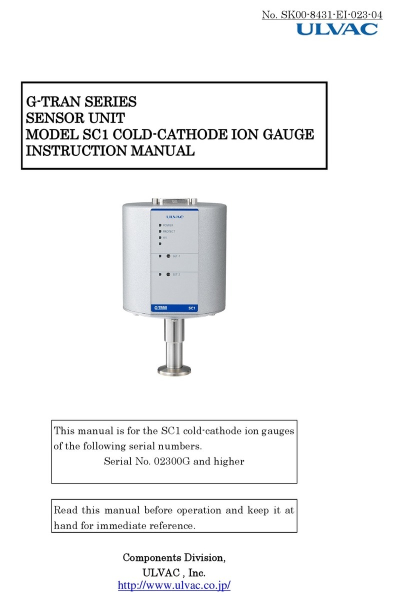
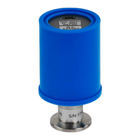
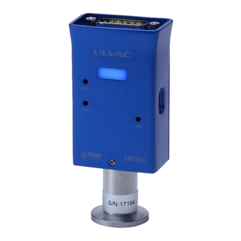
Ulvac G-Tran Series User manual

No.SK00-9664-EI-003-00
I
Vacuum Gauge
Instruction Manual
G-TRAN series
Multi Ionization Gauge Sensor unit
Analog Output Type Model SH200-A
Serial Communication Type Model SH200-R
(Option)
(Option)
This manual is intended for products with serial numbers below or later.
SH200-A: S/N 00001~
SH200-R: S/N 00001~
Please read this manual before using this product and keep it in a
safe place so that you can use it at any time.
ULVAC,Inc. Components Division
https://www.ulvac.co.jp/en/

II
Before using this product
Thank you very much for purchasing our product.
When you receive the product, please check that the product you received is the
correct one, and check for any damages caused by transportation.
To ensure many years of use from the product, please read the instruction manual
and fully understand the safety precautions, specifications, and operating
instructions before installing, operating, inspecting, or servicing the product.
The copyright of the instruction manual belongs to ULVAC, Inc.
No part of the instruction manual may be copied without our permission.
Also, the instruction manual may not be disclosed or transferred to any third
party without our written consent.
Please note that the instruction manual contents are subject to change or
revision without any notice due to changes in specifications and improvement of
the product.
Safety symbol marks
This instruction manual uses the safety symbol marks as the warning indications for
the operator to understand the matters that must be observed. The terms of the
safety symbol marks are as follows:
*WARNING*
It indicates a hazardous situation that could cause death or serious
injury if the warning is ignored.
Ignoring this warning may cause serious damage to the operator's
life or the plant facilities (Also include this product).
*CAUTION*
It indicates a dangerous situation that could cause minor or
moderate injury when the caution is ignored.
Ignoring this caution may cause minor injury to the operator,
product damage, or situations that require product adjustment.

III
Safety precautions
To use the G-TRAN series sensor unit (hereinafter referred to as this unit) safely,
please be sure to read the instruction manual and the following safety precautions:
*WARNING*
Power shutoff
If this unit is damaged, shut off the power immediately. Failure to do so may
cause fire or electric shock.
*WARNING*
Power shutoff
If this unit generates abnormal heat, smoke, or unusual smells, shut off the
power immediately. Failure to do so may cause a fire.
*WARNING*
High-temperature warning
Do not touch the sensor unit during and immediately after the operation because
its surface is hot. Touching it may cause burns.
*WARNING*
Power supply voltage
Before turning on the power supply, make sure that this unit's operating voltage
and the power supply are correct. If the wrong power supply is connected, it may
damage this unit and the equipment connected to it or cause a fire. In particular,
do not apply a voltage exceeding DC28V. The overvoltage category is Category I.
*WARNING*
Power supply with lightning surge protection
Use a power supply with lightning surge protection.
If the power supply does not have lightning surge protection, it may damage this
unit and the equipment connected to it or cause a fire.
*WARNING*
Excess pressure in a vacuum chamber
Do not connect the sensor unit to a place where the pressure inside the sensor
unit exceeds the atmospheric pressure. If the pressure inside the sensor unit
exceeds the atmospheric pressure, the sensor unit may be damaged, or the sensor
unit may fly out from the connection, causing harm to the surrounding, including
the human. If the pressure inside the sensor unit exceeds the atmospheric
pressure, install an isolation valve to prevent the pressure inside the sensor
unit from exceeding the atmospheric pressure.
*WARNING*
Protective earth
This unit must be electrically connected to a grounded vacuum chamber. Use a
conductive metal clamp
for the NW flange. If failing to ground properly, it cannot
indicate the correct pressure. It may also damage this unit and the equipment
connected to it or cause a fire.
If insulation from the vacuum chamber is required, the case part (the shell part
of the D-sub connector) needs to be D-type-grounded (class 3).
*WARNING*
Operating environment (Condensation, Humidity)
Do not use this unit in a place where humidity is high, and condensation occurs
or where this unit is exposed to water. If water enters inside this unit, it may
cause a failure, electrical leakage, or fire.
Also, operating this unit outside the temperature range of the specification may
cause failure and fire.
*WARNING*
Turn off the power supply when replacing the sensor
Be sure to turn off the power supply when replacing the sensor unit. DC330V may
be applied to the grid, which may cause fire or electric shock.
*WARNING*
Disassembly is prohibited
Do not disassemble this unit. Disassembling this unite may cause fire or electric
shock. The operation is not guaranteed if the unit is disassembled.
*WARNING*
Modification is prohibited
Do not modify this unit. Modifying this unite may cause fire or electric shock.
The operation is not guaranteed if the unit is modified.

IV
*WARNING*
Check power supply polarity
Before turning on the power supply, ensure that the polarities of this unit's
operating voltage and the supply voltage are correct. If the wrong polarities are
connected, it may damage this unit and the equipment connected to it or cause a
fire.
*WARNING*
Turn on the power supply
Turn on the power supply after connecting all components, including the sensor
unit, displays, PLC(Programmable Logic Controller), cables. Failure to do so may
damage this unit and the equipment connected to it or cause a fire. Also, the
filament of the sensor unit may break.
*WARNING*
Condensation
Do not use this unit in a place where humidity is high, and condensation occurs
or where this unit is exposed to water. If water enters inside this unit, it may
cause a failure, electrical leakage, or fire.
*WARNING*
Foreign matters entering the sensor
Protect this unit from foreign matters such as metals and flammable materials
from entering through its opening. Foreign matters may damage this unit or cause a
fire.
*WARNING*
Check wiring
Make sure that the connection cable to each pin does not touch other pins or the
case. Also, be careful with the ping assignments. Incorrect wiring may damage this
unit and the equipment connected to it or may cause a fire.
*CAUTION*
Cable installation
Avoid installing cables close to or parallel to electric power lines, power
lines, high voltage lines, high-frequency lines. Doing so may cause malfunction.
*CAUTION*
Remote host with noise resistance
Use an isolation type with high noise resistance for remote hosts such as PCs
and PLCs. Otherwise, it may cause malfunction or failure.
*CAUTION*
Parts with life span
The electric circuit in this unit uses an aluminum electrolytic capacitor.
Generally, an aluminum electrolytic capacitor has a life span, and the higher the
ambient temperature, the shorter the life. To prevent damage to this unit, we
recommend that you have this unit serviced at our service site about once every
three years.

V
Revision history
Date
Number
Reason
2021/03/03 00 First edition

VI
Table of contents
BEFORE USING THIS PRODUCT .......................................II
SAFETY SYMBOL MARKS .............................................II
SAFETY PRECAUTIONS .............................................III
REVISION HISTORY .................................................V
TABLE OF CONTENTS ...............................................VI
1. DEDICATED APPLICATION ............... 1
2. SPECIFICATION ....................... 2
2.1. UNPACKING AND CHECKING ACCESSORIES..... 3
Accessories ................. 3
Items that need to be ordered
separately .......................... 3
2.2. SH200 STANDARD SPECIFICATIONS ........ 4
2.3. SH200 STAND-ALONE MODE STANDARD
SPECIFICATIONS ........................... 6
2.4. SWU COMBINATION MODE (SH200+SWU)
STANDARD SPECIFICATIONS .................... 6
2.5. SPU COMBINATION MODE (SH200+SPU)
STANDARD SPECIFICATIONS .................... 7
2.6. SAU COMBINATION MODE
(SH200+SWU/SPU+SAU) STANDARD SPECIFICATIONS 8
3. HANDLING PRECAUTIONS ................ 9
3.1. PRECAUTIONS ON OPERATING ENVIRONMENT ... 9
3.2. PRECAUTIONS ON POWER SUPPLY.......... 10
3.3. PRECAUTIONS ON INSTALLATION.......... 10
3.4. PRECAUTIONS ON OPERATION AND HANDLING.. 11
3.5. CHECK ITEMS IMMEDIATELY AFTER THE
OPERATION .............................. 11
4. NAME OF EACH PART AND ITS FUNCTION.. 12
4.1. CONTROLLER SECTION SH200-A/R ....... 12
4.2. PANEL SECTION SH200-A/R .......... 13
4.3. I/O CONNECTOR ANALOG OUTPUT TYPE SH200-
A ............................... 14
4.4. I/O CONNECTOR SERIAL COMMUNICATION TYPE
SH200-R .............................. 15
4.5. SWU/SPU I/O CONNECTOR............ 16
4.6. SAU I/O CONNECTOR .................17
5. POWER SUPPLY INTERNAL CIRCUIT ...... 18
6. EACH MODE SETTING(COMMON TO SH200-
A/R).................................. 18
7. STATUS OF EACH LED ................. 19
7.1. POWER LED STATUS(COMMON FOR SH200-
A/R)................................19
7.2. SWU/SPU LED STATUS(COMMON FOR SH200-
A/R)................................19
7.3. SAU LED STATUS(COMMON FOR SH200-A/R)
................................19
7.4. POWER LED BLINKING STATUS(SH200-A
ONLY)................................19
8. CONTROL INPUT SIGNAL ............... 20
8.1. CONTROL INPUT SIGNAL (SH200-A ONLY) ..20
8.2. FIL ON/OFF SIGNAL.................21
8.3. FIL 1/2 SIGNAL....................21
8.4. DEGAS ON/OFF SIGNAL ...............22
9. MEASURED VALUE OUTPUT(COMMON TO SH200-
A/R).................................. 23
9.1. PRESSURE CONVERSION FORMULA ..........23
9.2. SH200 STAND-ALONE MODE MEASURED VALUE
OUTPUT ................................23
9.3. SH200+SWU MEASURED VALUE OUTPUT......24
9.4. SH200+SPU MEASURED VALUE OUTPUT......25
9.5. SH200+SWU(SPU)+SAU MEASURED VALUE
OUTPUT ................................26
9.6. SIMPLIFIED CONVERSION TABLE ..........27
9.7. BMR2 COMPATIBILITY OUTPUT(MODE SETTING

VII
9)............................... 28
Pressure conversion formula 28
10. CONTROL OUTPUT SIGNAL ............ 29
10.1. CONTROL OUTPUT SIGNAL (SH200-A
ONLY) ............................. 29
10.2. SERIAL COMMUNICATION OUTPUT SIGNAL
(SH200-R ONLY) ........................ 29
10.3. SENSOR ERROR SIGNAL (SH200-A ONLY) 30
SH200 stand-alone mode ... 30
SWU combination mode ..... 30
SPU combination mode ..... 30
SAU combination mode ..... 30
10.4. SETPOINT OPERATION SIGNAL (SH200-A
ONLY) ............................. 31
10.5. EMISSION VALID SIGNAL AND CONNECTION
CHECK SIGNAL (SH200-A ONLY) .............. 31
Emission valid signal
(SH200-A only) ..................... 31
Connection check signal
(SH200-A only) ..................... 31
Differences between mode
setting (SH200-A only) ............. 31
Filament power monitoring
signal (SH200-A only) .............. 31
11. SETPOINT SETTING (SH200-A ONLY) .. 32
11.1. OPERATING PRESSURE RANGE OF SETPOINT 32
11.2. SETPOINT ON/OFF PRESSURE......... 33
11.3. SETPOINT SETTING OF SH200-A ...... 33
12. FILAMENT POWER MONITORING SIGNAL . 33
12.1. HOW TO CHECK THE FILAMENT POWER
MONITORING SIGNAL ON SH200-R.............. 34
13. SAU ATMOSPHERIC PRESSURE ADJUSTMENT.
................................. 34
13.1. ATMOSPHERIC PRESSURE ADJUSTMENT OF
SH200-A ............................. 34
13.2. ZERO POINT ADJUSTMENT OF SH200-A.. 34
13.3. ADJUSTMENT OF SH200-R........... 34
14. SWU ATMOSPHERIC PRESSURE AND ZERO
POINT ADJUSTMENT........................ 35
14.1. ATMOSPHERIC PRESSURE ADJUSTMENT OF
SH200-A ..............................35
14.2. ZERO POINT ADJUSTMENT OF SH200-A ...35
14.3. ADJUSTMENT OF SH200-R............35
15. HOW TO USE SERIAL COMMUNICATION
(SH200-R)............................ 36
15.1. COMMUNICATION SPECIFICATIONS........36
15.2. SETTINGS .......................36
Connection Diagram ........36
Baud rate setting .........37
Address setting ...........37
Standard data format ......38
Command List ..............38
When the command is received
normally ..........................38
When the command is not
received normally ...................38
15.3. COMMAND ........................39
Reading measurement values
and status ..........................39
Writing status ............39
Reading status ............39
Checking errors ...........39
SAU/SWU/SPU atmospheric
pressure adjustment command .........39
SAU/SWU/SPU zero point
adjustment command ..................40
SAU/SWU atmospheric pressure
and zero point adjustment
initialization command ..............40
Checking the value of
filament power monitoring of SH200 ..40
Reading Software Version ..40
Reading Setpoint1 Value ...40
Reading Setpoint2 Value ...41
Writing setpoint1 value ...41
VIII
Writing setpoint2 value .. 41
Reading mode setting ..... 41
Writing mode setting ..... 41
Reading address setting .. 41
Writing address setting .. 42
Reading communication
speed ......................... 42
Writing communication
speed ......................... 42
Enabling checksum
confirmation ....................... 42
Disable checksum
confirmation ....................... 42
Checksum confirmation status
confirmation ....................... 42
Checksum ................. 43
15.4. STATUS SETTING LIST.............. 44
When writing status ...... 44
When reading status ...... 45
15.5. ASCII CODE TABLE ............... 47
16. REPLACEMENT OF SENSOR ............ 48
16.1. TOOL.......................... 48
16.2. REMOVING SENSOR ................. 48
16.3. INSTALLING SENSOR ............... 48
17. TROUBLESHOOTING .................. 49
17.1. TROUBLESHOOTING ................. 49
17.2. THE INTERNAL ELECTRODE DISCONNECTION
CHECK ............................. 53
17.3. INSULATION BETWEEN THE PIN AND THE CASE
OF THE SENSOR. .......................... 53
18. TECHNICAL REPORT ................. 54
18.1. MEASUREMENT PRINCIPLE ............ 54
18.2. TYPE OF MEASURING GAS AND SPECIFIC
SENSITIVITY COEFFICIENT ................... 54
19. WARRANTY ......................... 57
20. EC DECLARATION OF CONFORMITY ..... 59
21. CERTIFICATE OF CONTAMINATION ..... 60
22. DIAGRAMS ......................... 61
22.1. SH200-A/R AND SWU CONNECTION
DIAGRAM ..............................61
22.2. SH200-A/R,SWU AND SAU CONNECTION
DIAGRAM ..............................62
22.3. SH200-A/R DIMENSIONS ............63
22.4. SENSOR DIMENSIONS ................64
22.5. DISPLAY UNIT CABLE ...............65
22.6. UNIT CABLE GUC-200P .............66
22.7. UNIT CABLE GUC-200A .............67

1
1. Dedicated application
SH200 and ST200 series can check various settings and status using the dedicated
applications below.
Please refer to the application instruction manual for details.
・UL-MOBI_Windows (Supported OS: Windows 10 64bit or later)
・UL-MOBI_Andoroid (Supported OS: Android 6.0 or later)
Download: UL-MOBI_Android Google Play
UL-MOBI_Windows https://www.ulvac.co.jp/download/en/application/
UL-MOBI_Windows Instruction manual
https://www.ulvac.co.jp/download/en/application/
Function
Note
UL-MOBI
Windows
UL-MOBI
Android
DATA Check the pressure numerically and draw a
graph. △△
DATA LOG Pressure indication value LOG and CSV
output. ◎◎
SAMPLING Check and change the sampling cycle. ◎◎
FIL・DEGAS Display filament and DEGAS status. ◎◎
Pressure unit Change the pressure unit. ◎◎
SETPOINT 1/2/3 Check and change of setpoint. 〇〇
Baud rate Check and change of baud rate. ●●
Mode Check and change of mode. ●●
Address Check and Change of address. ●●
ATM point
adjust
Adjusts the atmospheric pressure of SAU
and SWU. ▲▲
Adjust clear Reset the zero point and atmospheric
pressure adjustment of SAU and SWU. ▲▲
Status Display errors. △△
New password Changes a password. ◎◎
◎:It can be checked and changed at any time
〇:It can be checked at any time. A password is required in order to change
when energized at 24V.
●:It can be checked at any time. It can be changed only when 24V is cut off.
△:It can be done only when energized at 24V.
▲:It can be done only when energized at 24V. A password is required.
※A password is required to change the settings, as careless setting change may cause
the failure of the vacuum system.
The password can be set to any four numbers.
※The software of this unit uses the pressure unit [Pa].
When changing the pressure unit on UL-MOBI, UL-MOBI converts the pressure unit to
[Pa] and writes it to this unit.
Please note that rounding errors may occur when converting units.

2
2. Specification
The Multi ionization gauge sensor unit SH200 is a vacuum gauge that can measure the
high vacuum pressure by connecting a dedicated sensor unit (B-A gauge type).
The following three types of interfaces are available. Users can select the
specification that best suits the communication protocol.
Analog output type : SH200-A (this manual)
Serial communication type : SH200-R (this manual)
EtherCAT communication type : SH200-E (separate manual)
(Hereinafter, SH200 refers to both SH200-A and SH200-R.)
By connecting an optional unit to SH200, SH200 can control each connected unit.
According to the unit connected, the three modes below are available to measure from
high vacuum to atmospheric pressure.
※SWU series is available in the Windows/Android-compatible【SWU10-U】and
RS-485 communication-compatible 【SWU10-R】. SWU written in this manual
is SWU10-R. SWU10-U cannot connect to SH200.
※SPU and SWU cannot operate at the same time.
※SAU cannot connect to SH200 without SPU or SWU.
10
-4
10
+3
10
+4
10
-8
10
-7
10
-6
10
-5
10
+5
SAUコンビネーションモード
圧力センサユニット(SAU)
+SWU/SPU
+SH200
10
-3
10
-2
10
-1
10
0
10
+1
10
+2
モードおよび構成
圧力(Pa)
SH200単体モード
SH200のみ
SPU/SWUコンビネーションモード
ピラニゲージ(SWU/SPU)
+SH200
SH200
SAU
SH200
SPU
SWU
SH200
SPU
SWU
Mode and
configuration
SPU/SWU Combination
mode
Pirani gauge (SWU/SPU)
+ SH200
SAU Combination mode
Pressure sensor unit
(SAU)
+ SWU/SPU + SH200
Pressure (Pa)
S
H200 Stand-alone mode
SH200 only

3
2.1. Unpacking and checking accessories
When the product arrives, please unpack, and check the product. Also, please check
for any damage from transportation and make sure that there are all accessories.
Accessories
Multi ionization gauge sensor unit SH200 (main unit) 1
Sensor for SH200※1
Quick manual (regular paper) 1
※Depending on the order, the sensor for SH200( M-4* or M-3*) may or
may not be included.
Items that need to be ordered separately
Sensor for SH200
(flange size)
M-44 (NW16), M-45 (NW25), M-46 (ICF70)
M-34 (NW16), M-35 (NW25), M-36 (ICF70)
Connector for SH200 D-sub15pin connector (female), M2.6 screw ※unwired
Calibration certificate Calibration certificate, JCSS calibration certificate
Inspection certificate
Traceability certificate
Display unit Model ISG1 (DC24V power supply)
Display cable Cable between SH200 and display unit
2m, 5m, 10m, 15m, 20m, 25m, 30m, 35m, 40m
Pirani gauge SWU SWU and SPU cannot operate at the same time.
Sensor for SWU SWP-16, SWP-25, SWP-R1/8, SWP-P18, SWP-P15, SWP-CF16
Pirani gauge SPU SWU and SPU cannot operate at the same time.
Sensor for SPU WP-01, WP-02, WP-03, WP-16
Pressure sensor unit SAU
Unit cable GUC-200P Between SH200 and SWU/SPU 0.5m, 1m, 2m
Unit cable GUC-200A Between SH200 and SAU 0.5m, 1m, 2m
→
Display unit
Display Cable
Sensor
f
or SWU
※SWU can be replaced with SPU.
GUC
-200A
GUC
-200P
SAU
SWU
SH200
Connector
f
or SH200
(unwired)
Sensor
f
or SH200

4
2.2. SH200 standard specifications
Name Multi ionization gauge sensor unit
Type Analog output type Serial communication type
Model SH200-A SH200-R
Compatible sensor M-44 (NW16), M-45 (NW25), M-46(ICF70): 1
【M-34 (NW16), M-35 (NW25), M-36 (ICF70): Option】
Compatible
measuring unit
Pirani gauge SWU : 1
Pirani gauge SPU : 1
Pressure sensor unit SAU : 1
※SWU and SPU cannot operate
together.
Repeatability (N2) SH200 stand-alone mode: ±2%
Measuring gas type Indicate pressure as sensitivity to N2gas
Emission current 1mA (1.0×10⁻³Pa or lower), 10uA (1.0×10⁻³Pa or higher)
DEGAS Electron bombard method
SH200 starts DEGAS at an emission current of 1mA, grid voltage
of approx.330V, and approx.1.0×10-3Pa or less.
Sampling time 5times in 60msec moving average
Measured Value
output
Output voltage DC 0 to 10V, LOG output 0.75V/1 digit
Pressure[Pa] conversion formula
V=7.25+0.75*(LogP-2) P=10^{(V-7.25)/0.75+2}
Update time 60msec
Resolution approx.2.5mV
Output
impedance
100Ω
Control output
signal
Sensor Error, Setpoint1/2/3,
Emission valid,
Filament electric power
monitoring
Rated: Less than the supply
voltage,50mAMAX
Saturation voltage 1V
Communication USB Type-C
RS-232C, RS-485 half duplex
Communication
speed
9600/19200/38400bps
LED display POWER: Power, error, filament status display
SWU/SPU: Pirani gauge SWU/SPU status display
※SWU/SPU combination mode, SAU combination mode only
SAU: Pressure sensor SAU status display
※SAU combination mode only
Sensor
Material
M-4* Filament 1 and 2: Ir/Y2O3coated
Other: PtC-Mo, SUS304, W, Kovar glass, Kovar/Ni plated
M-3* Filament 1: Ir/Y2O3coated Filament 2: Tungsten
Other: PtC-Mo, SUS304, W, Kovar glass, Kovar/Ni plated
Sensor
breaking pressure
2.0×10+5Pa(absolute pressure)
※Please consider the breaking pressure of flanges and clamps
separately.
Sensor
internal volume
M-44: 17cm3, M-45: 19 cm3, M-46: 17 cm3
M-34: 17cm3, M-35: 19 cm3, M-36: 17 cm3
Operating
temperature range
10℃to 50℃

5
Heating
temperature
Sensor only 150℃(with controller SH200 removed)
Sensor flange part 80℃(only when the main unit is installed
horizontally, the controller SH200 ambient temperature is 50℃
or less)
※When heating, deviations from specifications, such as
accuracy, is observed.
Operating humidity
range
15% to 80% (no condensation)
Storage
Temperature
-20℃to 65℃ (no condensation when not energized)
IP Rating IP30
Power supply
voltage
DC20V to 28V (ripple, noise 1% or less)
※Power supply voltage at the end of SH200 connector
Steady state : approx. 5.5W
Maximum (During degassing) : 8W or less
When power turned on : 800mA or less, 4msec or less
Overvoltage category:Category 1
CE marking
Verified with SPU and
SAU connection
Low Voltage Directive EN61010-1:2010(Third Edition),A1:2019
2014/35/EU
EMC Directive EN61326-2-3:2013
2014/30/EU
Electrostatic Test IEC61000-4-2:2008
Radiated Electromagnetic Field Test
IEC61000-4-3:2006+A1:2007+A2:2010
Transient burst test IEC61000-4-4:2004+A1:2010
Surge test IEC61000-4-5:2005
Conduction test IEC61000-4-6:2008
Commercial magnetic field test
IEC61000-4-8:2009
Radiation field intensity measurement
CISPR11:2009+A1:2010:Group 1 Class A
RoHS EN50581:2012
2011/65/EU
Display cable length: 40m or less
Cable length between SH200 and SWU, SPU, SAU: 2m or less
I/O connector D-sub15 pin (male) connector, M2.6 screw
Weight Controller SH200: approx.280g
M-44: 80g, M-45: 80g, M-46: 300g
M-34: 80g, M-35: 80g, M-36: 300g
Dimensions approx.69mm×63mm×90mm (SH200 only)

6
2.3. SH200 stand-alone mode standard specifications
Measurable
pressure range
(N2)
5.0×10⁻⁸Pa to 1.0×10+1Pa
Accuracy (N2) 5.0×10⁻⁸Pa to 1.0×10+1Pa: ±15%
POWER LED status White : Start up
Blue : Normal operation
Green : Filament is on
Blinking Red: Power failure
Control input
signal
FIL ON/OFF, FIL 1/2
DEGAS ON/OFF
Open collector input,
Negative logic
2.4. SWU combination mode (SH200+SWU) standard specifications
Measurable
pressure range
(N2)
5.0×10⁻⁸Pa to 1.0×10+5Pa
When pressure drops: SWU indicates 2Pa or lower, SWU ⇒SH200
When pressure rises: SWU indicates 3Pa or higher, SH200⇒SWU
※SH200 measurement can be forcibly turned off with the
control signal.
Accuracy (N2)
Pressure range Accuracy
5.0×10⁻⁸Pa to 4.0×10⁻¹Pa ±15%
4.0×10⁻¹Pa to 3.0×10+0Pa ±10% to ±15%
3.0×10+0Pa to 1.0×10+4Pa ±10%
1.0×10+4Pa to 1.0×10+5Pa ±20%
In the overlapping pressure range of 0.4Pa to 3.0Pa, the
measured pressure of the Pirani gauge and SH200 is adjusted and
output.
※SWU and SH200 have gas species dependency. Please note
the difference in pressure indication when gauges switch.
POWER LED status White : Start up
Blue : Normal operation to SWU measurement range
Green : SH200 filament is on
Red : SWU power failure
Blinking Red: SH200 power supply voltage error
Control input
signal
FIL ON/OFF, FIL 1/2, DEGAS ON/OFF
Open collector input, Negative logic
※When FIL ON/OFF signal is Lo input, the
filament of SH200
is off.

7
2.5. SPU combination mode (SH200+SPU) standard specifications
Measurable
pressure range
(N2)
5.0×10⁻⁸Pa~1.0×10+4Pa
When pressure drops: SPU indicates 2Pa or lower, SPU ⇒
SH200
When pressure rises: SPU indicates 3Pa or higher, SH200⇒SPU
※SH200 measurement can be forcibly turned off with the
control signal.
Accuracy (N2)
Pressure range Accuracy
5.0×10
-8
Pa to 4.0×10
-1
Pa ±15%
4.0×10⁻¹Pa to 1.0×10+0Pa ±15% to ±30%
1.0×10+0Pa to 1.0×10+3Pa ±15%
1.0×10+3Pa to 3.0×10+3Pa ±30%
3.0×10+3Pa to 1.0×10+4Pa Accuracy not guaranteed
In the overlapping pressure range of 0.4Pa to 3.0Pa, the
measured pressure of the Pirani gauge and SH200 is adjusted and
output.
※SPU and SH200 have gas species dependency. Please note
the difference in pressure indication when gauges switch.
POWER LED status White : Start up
Blue : Normal operation to SPU measurement range
Green : SH200 filament is on
Red : SPU Power failure
Blinking Red: SH200 Power failure
Control input
signal
FIL ON/OFF, FIL 1/2, DEGAS ON/OFF
Open collector input, Negative logic
※When FIL ON/OFF signal is Lo input, the filament
of SH200
is off.

8
2.6. SAU combination mode (SH200+SWU/SPU+SAU) standard specifications
Measurable
pressure range
(N2)
5.0×10⁻⁸Pa to 1.0×10+5Pa
When pressure drops:
SAU indicates 10000Pa or lower, SAU ⇒SWU/SPU
SWU/SPU indicates 2Pa or lower, SWU/SPU ⇒SH200
When pressure rises:
SWU/SPU indicates 3Pa or higher, SH200 ⇒SWU/SPU
SAU indicates 10000Pa or higher, SWU/SPU ⇒SAU
※SH200 measurement can be forcibly turned off with the
control signal.
Accuracy (N2)
Pressure range Accuracy
When
using
SWU
5.0×10⁻⁸Pa to 4.0×10⁻¹Pa ±15%
4.0×10⁻¹Pa to 3.0×10+0Pa ±10% to ±15%
3.0×10+0Pa to 1.0×10+4Pa ±10%
1.0×10+4Pa to 3.0×10+5Pa ±3%F.S. (±3.0×10+3Pa)
When
using
SPU
5.0×10
-8
Pa to 4.0×10
-1
Pa ±15%
4.0×10
-1
Pa to 1.0×10
+0
Pa ±15% to ±30%
1.0×10+0Pa to 1.0×10+3Pa ±15%
1.0×10+3Pa to 1.0×10+4Pa Accuracy not guaranteed
1.0×10+4Pa to 3.0×10+5Pa ±3%F.S. (±3.0×10+3Pa)
In the overlapping pressure range of 0.4Pa to 3.0Pa, the
measured pressure of SWU/SPU and SH200 is adjusted and output.
※Since SAU
measures by gauge pressure and SWU/SPU measures
by absolute pressure, errors between SAU and SWU/SPU
occur due to the altitude and air pressure.
※SWU/SPU and SH200 have gas species dependency. Please
note the difference in pressure indication when gauges
switch.
POWER LED status White : Start up
Blue : Normal operation to SAU, SWU/SPU measurement range
Green : SH200 filament is on
Red : SWU/SPU, SAU Power failure
Blinking Red: SH200 Power failure
Control input
signal
FIL ON/OFF, FIL 1/2, DEGAS ON/OFF
Open collector input, Negative logic
※When FIL ON/OFF signal is
Lo input, the filament of SH200
is off.

9
3. Handling precautions
*Note*
Please read this chapter before using this unit.
3.1. Precautions on operating environment
Ensure ventilation
Do not place this unit in a sealed container. Install it in a place where
ventilation is ensured. Sealing it may increase the temperature of the electronic
components in the power supply and shorten its life.
Precautions for gases used
M-44
M-45
M-46
Both filaments 1 and 2 are Ir/Y2O3coated. If exposed to chemically
active gases such as halogens and halogen-based gases, problems such as
filament disconnection and changes in pressure characteristics may
occur.
If operating this unit in such an environment, install an isolation
valve between this unit and the vacuum chamber to protect it from
exposure to these gases.
M-34
M-35
M-36
Filament 1 is Ir/Y2O3coated. If exposed to chemically active gases
such as halogens and halogen-based gases, problems such as filament
disconnection and changes in pressure characteristics may occur.
Filament 2 is made of tungsten. In an atmosphere containing a lot of
oxygen, the life of the filament may be shortened due to burnout
(approx. 3hours at 1Pa air introduction).
If operating this unit in such an environment, install an isolation
valve between this unit and the vacuum chamber to protect it from
exposure to these gases.
Operation in the corrosive gas atmosphere
If this unit is exposed to corrosive gases or chemically active gases such as
halogen or halogen-based gases, troubles such as filament disconnection or changes
in pressure characteristics may occur. If operating this unit in such an
environment, install an isolation valve between this unit and the vacuum chamber to
protect it from exposure to these gases.
Operation in CVD gas atmosphere
If this unit is exposed to CVD (Chemical Vapor Deposition) source gases and gases
that accumulate, such as oil mist in rotary pumps, troubles such as filament
disconnection or changes in pressure characteristics may occur. If operating this
unit in such an environment, install an isolation valve between this unit and the
vacuum chamber to protect it from exposure to these gases.
Moisture and deposits
If many deposits, such as moisture or organic matters, that evaporate gradually
exist in the sensor unit, it will affect the vacuum side pressure accuracy and
response speed. Please consider the installation location and method to prevent
deposits.
Effect of magnetic field
The pressure indication of this unis is affected by a magnetic field of 0.002T (20
Gauss) by approximately 10%. If this unit is affected by a magnetic field, install a
magnetic shield.

10
Temperature fluctuation
Due to the measurement principle, the ambient temperature of the sensor unit of the
Pirani vacuum gauge affects the measurement value.
Pay attention to the installation position so that the ambient temperature does not
deviate significantly from the temperature during calibration (approx. 25℃).
Influence of electrons and ions
If there is a strong source of electrons or ions near the unit, it may not measure
the correct pressure. It also may damage this unit and cause a failure. Pay
attention to the installation location to avoid the influence of electrons and ions.
3.2. Precautions on power supply
Power supply
This unit must be connected to a power supply or an evaluation unit that is ground-
protected and complies with the standard for PELV (EN/IEC 60204-1).
Also, install this unit with a fuse to connect. If the voltage supplied to this
unit is less than DC20V, it will not indicate the accurate pressure.
The voltage drop of the power cable
The voltage drop of the power cable may cause the voltage supplied to this unit to
fall under DC20V. Please note that the voltage drop may occur, especially when the
cable thickness is thinner than AWG24.
Recommended cable length when DC power supply voltage is DC24V, and the ambient
temperature is 20℃: AWG26: 10m, AWG24: 20m, AWG22: 30m
3.3. Precautions on installation
Fixing method
Fix the cable so that no force is applied to the cable connection part.
Insert the unit cable securely and tighten the connector fixing screws firmly.
Life of female connector
The female connector used in the fitting part with this unit's sensor unit has a
life span. Poor contact of the connector will significantly shorten the sensor's
life, so try to avoid inserting and removing the connector as often as possible.
Make sure to tighten the sensor fixing screws firmly to prevent excessive force to
the connector.
Gas flow in the measurement system
The static pressure at the position where the sensor is connected is measured for
the pressure. Ensure that the sensor unit mounting opening is parallel to the gas
flow. In particular, do not allow gas to enter the sensor unit in the form of a
beam. Also, install the sensor unit to avoid the influence of the outgas.
Vibration
As the filament of the pirani sensor is as thin as φ25μm, avoid using it in a
place with a lot of vibration. Since the mechanical shock is the most common cause
of filament breakage, be careful when installing and handling it.
Outgas
Use an O-ring that outgases little to install the sensor unit. Using materials that
emit a lot of gas, such as a rubber tube or grease, to connect the sensor unit may
cause errors and shorten the product life.

11
3.4. Precautions on operation and handling
Impact
If dropping this unit or installing this unit in a place subject to large
vibrations, the impact or vibration may cause disconnection of the filament, grid,
or ion collector of the sensor or damage this unit.
Measurement
Measure after running for at least 20 minutes.
Packaging for transportation
When transporting this unit, please return it to the factory default condition.
This unit may be damaged if transported unpackaged or in the condition that it is
attached to the equipment.
Repair
Please contact the distributor, ULVAC, or service offices indicated in the
instruction manual for repair.
Disposal
Please dispose of this unit according to the local regulations.
In particular, if the sensor unit is used in an atmosphere that may pose a danger
to humans, please use a specialized disposal company to dispose of it.
Please note that customers are responsible for all disposal costs.
3.5. Check items immediately after the operation
Check the pressure indication of the pressure sensor unit SAU
Check the atmospheric pressure of the pressure sensor unit SAU immediately after
the operation. If necessary, adjust the atmospheric pressure.
Errors due to the altitude of the place where SAU is installed and low atmospheric
pressure
When using SAU at an altitude of 500m or higher or the atmospheric pressure of
950hPa or lower, adjust the atmospheric pressure.
Gas species dependency
The pressure value and accuracy of this unit and pirani detection unit differ
depending on the gas type to be measured. The accuracy of this unit is based on the
measurement of nitrogen gas. Please note that if you use a gas other than nitrogen.

12
4. Name of each part and its function
4.1.
Controller section SH200-A/R
Fig. 4-1 Diagram of the mechanism part
Name
Function
①I/O connector Fitting screw to the hood of I/O Connector
(D-sub15 pin(male), M2.6 screw)
②Sensor unit
fixing screw
Screw to fix the sensor (hexagon socket head locking screw M3)
2 screws
Other manuals for G-Tran Series
11
This manual suits for next models
8
Table of contents
Other Ulvac Measuring Instrument manuals

Ulvac
Ulvac MBD-D User manual

Ulvac
Ulvac G-TRAN CCMT-D Series User manual

Ulvac
Ulvac G-TRAN SW100-A User manual

Ulvac
Ulvac GP-1000G User manual

Ulvac
Ulvac G-Tran Series User manual

Ulvac
Ulvac GP-1G User manual

Ulvac
Ulvac AxTRAN ISX2 User manual

Ulvac
Ulvac MBD Series User manual

Ulvac
Ulvac SPU User manual

Ulvac
Ulvac G-Tran Series User manual