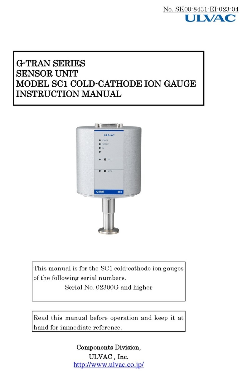
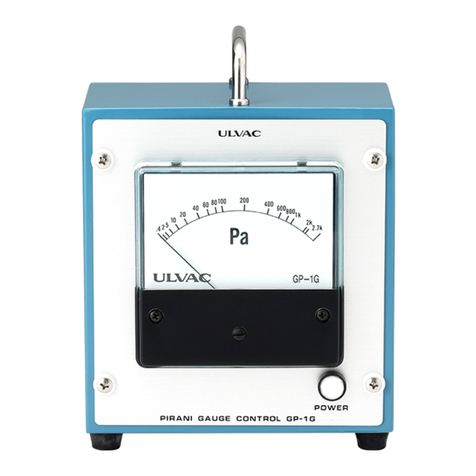
Ulvac MBS-C User manual

CRYO METER MBS-C
Instruction Manual
Export Control Policy
We recommend that ALL customers be sure to follow all
rules and regulations such as Foreign Exchange and
Foreign Trade Law when exporting or reexporting our
products.
D/N.MGMBS0CE, 2017DR08 ULVAC CRYOGENICS INCORPORATED


MZ0F001E,2013OR03 ULVAC CRYOGENICS INCORPORATED F-1
Introduction
Thank you for choosing our products. This instruction manual gives
information and precautions on handling, installation, operation, and
maintenance of the product.
This product is intended for use by qualified personnel who recognize shock
hazards and are familiar with the safety precautions required to avoid possible
injury. To ensure proper use of this product, read this instruction manual
carefully and keep this manual close at hand so that you can use for reference
during operation.
If you purchased our other products and/or optional devices with this product,
read relevant instruction manuals carefully.
1. About the personnel who are involved in handling our products
All personnel involved in handling our products should take a general safety
education and training that is officially accepted in the country where our product
is used. The personnel are also required to have specialized knowledge/skills and
qualification on the electricity, the machinery, the cargo handling, and the vacuum.
Especially, the personnel should be familiar with handling a cryopump in order to
use it safely. Since we offer a training session (which is subject to fees) as needed
for people who use cryopumps for the first time, please do not hesitate to contact
our Service Engineering Division to join the training session.
2. Warranty
2.1 Gratis warranty period and Warranty coverage
【Gratis warranty period】
Note that an installation period of less than one year after installation in your
company or your customer’s premises or a period of less than 18 months (counted
from the date of production) after shipment from our company, which is shorter, is
selected.
【Coverage】
(1) Failure diagnosis
As a general rule, diagnosis of failure should be done on site by customer.
However, ULVAC CRYOGENICS or our service network can perform this service
for an agreed fee upon the customer’s request. There will be no charge if the cause

F-2 ULVAC CRYOGENICS INCORPORATED
of the breakdown is found to be a fault of ULVAC CRYOGENICS.
(2) Damage during transportation
When damage by delivery/transportation is admitted, the product will be
repaired free of charge within the range of the guarantee expressed in the sales
contract.
(3) Breakdown repairs
There will be a charge for breakdown repairs, replacements and on-site visits
for the following seven conditions. In those cases the cost shall be your own
expense even though the product is within the warranty period.
①Breakdowns due to improper storage or handling, careless accident, software
or hardware design by the customer.
②Breakdowns due to modifications of the product without consent of the
manufacturer.
③Breakdowns due to maintenance of the product without authentic parts or
breakdowns resulting from using the product outside the specified
specifications of the product.
④Breakdowns due to contamination or corrosion caused by user’s use
conditions.
⑤Breakdowns due to natural disasters (such as fire, earthquake, flood,
lightning, salt damage, and so on) , environmental pollution, irregular voltage,
and /or usage of undesignated power source.
⑥Breakdowns that are outside the terms of warranty.
⑦Consumables and/or replacement service.
Since the above services are limited to within Japan, diagnosis of failures, etc are
not performed abroad. If you desire the after service abroad, please contact
ULVAC CRYOGENICS and consult us for details in advance.
2.2 Exclusion of opportunity loss from warranty liability
Regardless of the gratis warranty term, compensation to opportunity losses
incurred to your company or your customers by failures of ULVAC CRYOGENICS
products and compensation for damages to products other than ULVAC
CRYOGENICS products and other services are not covered under warranty.
MZ0F001E,2013OR03 ULVAC CRYOGENICS INCORPORATED F-3
2.3 Repair period after production is discontinued
ULVAC CRYOGENICS shall accept product repairs for seven years after
production of the product is discontinued.
3. Service Form
After the products are delivered, please fill out the following information in the
blanks. If you have any questions or technical problems, please feel free to contact
the nearest Customer Support Center or headquarters. Please refer to “Service
Network”.
Cryopump/Super trap Model :
Cryopump/Super trap Serial No. :
Refrigerator Model :
Refrigerator Serial No. :
Compressor Model :
Compressor Serial No. :
Temperature controller/Thermal display Model :
Temperature controller/Thermal display Serial No. :
Option Part Model :
Optional Part Serial No. :
4. Notes for repair and maintenance requests
We may decline your request for the repair or the maintenance of our products if
you refuse to give us information about the presence of the hazardous substance
and/or contaminant.
Also, please be aware that we do not accept liability for damages by the
contaminant, which might be caused during transportation to our office or the
nearest customer support center. To avoid such accident, please pay careful
attention to packing of the product
5.In case of breakdown and accident
When breakdown or accident occurs, we may ask for keeping the product on site
as it is or retrieving the product to investigate its cause. Also we may ask for
reporting the detailed process and/or the operating condition. When unidentified
malfunction was generated, please contact our Service Engineering Division or

F-4 ULVAC CRYOGENICS INCORPORATED
the nearest customer support center with reference to the chapter of Service
Network. We ask for cooperation about the above.
6.General Precautions
(1) It is strictly prohibited to duplicate, open, and transfer this instruction
manual or any of its parts to a third person without written permission from
ULVAC CRYOGENICS.
(2) Information in this document might be revised without a previous notice for
the specification change and the improvement of the product.
(3) If you have any questions or comments on this document, please do not
hesitate to contact us. The phone numbers of local customer support centers
are listed at the end of this manual.

MZ0F001E,2013OR03 ULVAC CRYOGENICS INCORPORATED F-5
Safety Considerations
Our products have been designed to provide extremely safe and dependable operation
when properly used. Following safety precautions must be observed during normal
operation and when servicing them.
CAUTION
WARNING
A warning describes safety hazards or unsafe practices
which could result in severe injury or loss of life.
Acaution describes safety hazards or unsafe practices which
could result in personal injury or equipment damage.
Toxic gas or chemicals used.
There is a risk of severe injury upon contact.
Corrosive chemicals used.
There is a risk of severe injury upon contact.
Flammable gas used.
There is a danger of fire or burn injury.
Explosive gas used.
There is a risk of fire or explosion.
Hazardous voltage .
Electric shock may cause severe injury or loss of life.
Hot heating part present.
There is a risk of burn injury.

F-6 ULVAC CRYOGENICS INCORPORATED
This page intentionally left blank

MZIW001E,2010.01 ULVACCRYOGENICSINCORPORATED IW-1
Disposal Consideration
Regulations and the ordinance concerning industrial waste treatment are provided in the
country and region to discard. When disposing our products, please process abandonment
according to relevant regulations and ordinance, etc.
When it seems that the cryopump or refrigerator has been used to evacuate a toxic or
dangerous material, you must contact a safety supervisor before discarding, and discard it
after removing the poisonous material according to directions of the safety supervisor.
We will offer you Material Safety Data Sheet (called MSDS) of our products upon your request.
If you have any questions, please contact our Service Engineering Division or the nearest
customer support center.
WARNING

IW-2 ULVAC CRYOGENICS INCORPORATED
This page intentionally left blank.

CRYO METER MBS-C Instruction Manual
TABLE OF CONTENTS
CHAPTER 1 General
1.1 Features ・・・・・・・・・・・・・・・・・・・・・・・・・・・・・・・・・・・・・・・・・・・・ 1
1.2 Models of MBS-C・・・・・・・・・・・・・・・・・・・・・・・・・・・・・・・・・・・・・ 2
1.3 Attached Connectors and Option Cables・・・・・・・・・・・・・・・・ 2
CHAPTER 2 General Specifications ・・・・・・・・・・・・・・・・・・・・・・・・・・・・・・・・ 3
CHAPTER 3 Connector Specifications・・・・・・・・・・・・・・・・・・・・・・・・・・・・・・・ 4
CHAPTER 4 Installation
4.1 Thermocouple Installation・・・・・・・・・・・・・・・・・・・・・・・・・・・・・ 5
4.2 Cable Connection・・・・・・・・・・・・・・・・・・・・・・・・・・・・・・・・・・・・・ 6
CHAPTER 5 Status Display・・・・・・・・・・・・・・・・・・・・・・・・・・・・・・・・・・・・・・・・・ 10
CHAPTER 6 Troubleshooting・・・・・・・・・・・・・・・・・・・・・・・・・・・・・・・・・・・・・・・ 11
Supplement 1. Assembling IO Connector and Connecting to MBS-C・・・・・・ 15
Supplement 2. Attachment, and Option cables・・・・・・・・・・・・・・・・・・・・・・・・・・ 18
Supplement 3. Pin assignments of MBS-compatible Cable・・・・・・・・・・・・・・・ 20
FIGURES
Figure 1-1 CRYO METER MBS-C・・・・・・・・・・・・・・・・・・・・・・・・・・・・・・・・・・・・・ 1
Figure 1-2 CRYO METER MBD・・・・・・・・・・・・・・・・・・・・・・・・・・・・・・・・・・・・・・・ 2
Figure 3-1 MBS-C Bottom View・・・・・・・・・・・・・・・・・・・・・・・・・・・・・・・・・・・・・・・ 4
Figure 4-1 Cryogenic Thermocouple Installation・・・・・・・・・・・・・・・・・・・・・・・ 5
Figure 4-2 K Thermocouple Installation・・・・・・・・・・・・・・・・・・・・・・・・・・・・・・・ 5
Figure 4-3 DC Power and Signal line Diagram・・・・・・・・・・・・・・・・・・・・・・・・・ 7
Figure 4-4 Cable Connection with MBD and Other Signal Line Diagram (1)
・・・・・・・・・・・・・・・・・・・・・・・・・・・・・・・・・・・・・・・・・・・・・・・・・・・・・・・・・ 8
Figure 4-5 Cable Connection with MBD and Other Signal Line Diagram (2)
・・・・・・・・・・・・・・・・・・・・・・・・・・・・・・・・・・・・・・・・・・・・・・・・・・・・・・・・・ 9
Figure 5-1 Front Panel of CRYO METER MBS-C・・・・・・・・・・・・・・・・・・・・・・・ 10
Figure A-1 Analog Output voltage (10K - 350K)・・・・・・・・・・・・・・・・・・・・・・・・ 12
Figure A-2 K Thermocouple output voltage・・・・・・・・・・・・・・・・・・・・・・・・・・・・ 13
Figure A-3 Dimensions of MBS-C ・・・・・・・・・・・・・・・・・・・・・・・・・・・・・・・・・・・・ 14
Fig. 1-A Connector-kit Package (Part No. 72D15F-S) ・・・・・・・・・・・・・・・・ 15
Fig. 1-B Parts in the Package ・・・・・・・・・・・・・・・・・・・・・・・・・・・・・・・・・・・・・ 15
Fig. 1-C Assembling of Connector-kit ・・・・・・・・・・・・・・・・・・・・・・・・・・・・・・ 16
ULVAC CRYOGENICS INCORPORATED Ⅰ

Table of Contents
ⅡULVAC CRYOGENICS INCORPORATED
TABLES
Table 1-1 Models of MBS-C・・・・・・・・・・・・・・・・・・・・・・・・・・・・・・・・・・・・・・・・・・ 2
Table 1-2 Cable Options for MBS-C “I/O” connecting・・・・・・・・・・・・・・・・・・・ 2
Table 2-1 Ratings of MBS-C ・・・・・・・・・・・・・・・・・・・・・・・・・・・・・・・・・・・・・・・・ 3
Table 3-1 Pin assignments and signals・・・・・・・・・・・・・・・・・・・・・・・・・・・・・・・ 4
Table 3-2 Connectors for wiring ・・・・・・・・・・・・・・・・・・・・・・・・・・・・・・・・・・・・ 4
Table 5-1 Status Display of MBS-C・・・・・・・・・・・・・・・・・・・・・・・・・・・・・・・・・・・ 8
Table 6-1 Troubleshooting Procedure・・・・・・・・・・・・・・・・・・・・・・・・・・・・・・・・・ 9
Table 2-A Example: Another combination of MBS-compatible Cable・・・・・ 16
Table 2-B Specified Option Cables (Mainly Thermal Control) :Ordered products・17
Table 3-A Pin assignments of MBS-compatible Cable connectors・・・・・・・・ 18
SHIPPING LIST
Our product has been fully inspected before shipment. However, please
make sure that there is no damage or shortage of delivered items by
checking the shipping list below and the exterior of the products.
COMPONENTS QUANTITY
CRYO METER MBS-C 1
I/O Connector-kit (*) 1
K(CA) plug 1
Instruction Manual 1
(*) Standard attachment in case of no option specified. Option cable and/or plugs
shown in Table 1-2 are attached instead of the kit by your specifying of the
option.
Note to Users
ULVAC CRYOGENICS INC. ships the products that have been passed the
inspection and adjustment procedure. Please contact our customer support if
you have any problem. Any modification and/or adjustment should not be
performed without our permission. Otherwise, it will cost on the verification,
inspection, adjustment, and repair even in the warranty period.

CRYO METER MBS-C Instruction Manual
1. General
1.1 Features
CRYO METER MBS-C is the successor to MBS.
MBS-C is installed on CRYO-U® cryopump manufactured by ULVAC CRYOGENICS, INC.
and measures temperature inside cryopump from 10K to 350K.
ump manufactured by ULVAC CRYOGENICS, INC.
and measures temperature inside cryopump from 10K to 350K.
The MBS-C measures temperature of 2nd stage of cryopump utilizing cryogenic
thermocouple (Chromel-AuFe thermocouple), and outputs handling no-voltage dry contacts
and analog signals.
The MBS-C measures temperature of 2nd stage of cryopump utilizing cryogenic
thermocouple (Chromel-AuFe thermocouple), and outputs handling no-voltage dry contacts
and analog signals.
With two dry contacts, MBS-C displays three different temperature levels of 2nd stage such
as below 20K, 20K to 280K, and 280K and above. The temperature is displayed on front
panel of MBS-C with LED indicator which has three different colors.
With two dry contacts, MBS-C displays three different temperature levels of 2nd stage such
as below 20K, 20K to 280K, and 280K and above. The temperature is displayed on front
panel of MBS-C with LED indicator which has three different colors.
The analog output signal indicates 2nd stage temperature with 5 – 0 Vdc corresponding to
10K – 350K range. Also, the analog line is isolated from the power line.
The analog output signal indicates 2nd stage temperature with 5 – 0 Vdc corresponding to
10K – 350K range. Also, the analog line is isolated from the power line.
Moreover, MBS-C has K(CA) thermocouple for 1st stage of cryopump or for detecting baffle
temperature, it therefore outputs the thermocouple electromotive force directly.
Moreover, MBS-C has K(CA) thermocouple for 1st stage of cryopump or for detecting baffle
temperature, it therefore outputs the thermocouple electromotive force directly.
The input power for MBS-C is DC24V. When operating MBS-C with CRYO METER MBD,
manufactured by ULVAC CRYOGENICS, the input power can be supplied from MBD to
MBS-C. MBD displays the numeric temperature value of 2nd stage.
The input power for MBS-C is DC24V. When operating MBS-C with CRYO METER MBD,
manufactured by ULVAC CRYOGENICS, the input power can be supplied from MBD to
MBS-C. MBD displays the numeric temperature value of 2nd stage.
Refer to Figure 1-1 and 1-2 for the appearances of MBS-C and MBD. Please refer to MBD
instruction manual for details. We offer two types of MBD, MBD-S (100V type) and MBD-T
(200V type).
Refer to Figure 1-1 and 1-2 for the appearances of MBS-C and MBD. Please refer to MBD
instruction manual for details. We offer two types of MBD, MBD-S (100V type) and MBD-T
(200V type).
(クライオポンプ内側)
Cryogenic thermocouple: 500L
(Inside cryopump)
JAE Type (See Table 3-2)
K(CA) thermocouple: 500L or 1000L
Figure 1-1 CRYO METER MBS-CFigure 1-1 CRYO METER MBS-C
ULVACCRYOGENICSINCORPORATED 1

CRYO METER MBS-C Instruction Manual
Figure 1-2 CRYO METER MBD-S, MBD-T
1.2 Models of MBS-C
We offer two models of MBS-C according to the length of K thermocouple. The models are
chosen depending on the size of cryopump and its design. Refer to Appended Figure 3 for
the dimensions.
Table 1-1 Models of MBS-C
Model Cryogenic thermocouple
[mm] K thermocouple [mm]
MBS-C2, C2a 500 500
MBS-C3, C3a 500 1000
(*1)C2a and C3a are the types for the use with thermal anchors. They have been added
mainly for cryopumps with caliber larger than 20 inches.
1.3 Attached Connectors and Option Cables
If no cable-option is specified, connector plugs shown in Table 3-2 will be attached. Wiring of
the connectors should be done by customers in this case.
If you purchase our equipment that inputs MBS-C signal, you can choose the specified cable
to connect MBS-C “I/O” connector as an option to avoid self-wiring job.
See Table 1-2 for the selection, and refer to “Supplement 2” to know the options in detail.
Table 1-2 Cable Options for MBS-C “I/O” connecting
Part Number Cable Name Length [m] Application Attachment
GP-HM30 MBS-compatible Cable (0.3m only) Same way as MBS
on wiring and connecting
3 Plugs for wiring (*1
MBD-HS30 MBD – MBS-C Cable 5,10,15,20 A cable for connecting
MBD and MBS-C
MBD-HS31 MBD - MBS-C Cable with
Contact signals 5,10,15,20 Option cable of MBD
MBS-C contacts available
(*1) The plugs are same type of MBS attachments. Note that it is easier for cabling MBD and MBS-C by
using MBD-HS30 than using GP-HM30, because other cables are required in the latter case.
Please specify MBS compatible cable when you need to wire in the same way as previous
models of MBS.
When purchased as a system, please contact us for appropriate cables.
2 ULVAC CRYOGENICS INCORPORATED

CRYO METER MBS-C Instruction Manual
2. General Specifications
Table 2-1 Ratings of MBS-C
Item Specifications
Ambient
Conditions
Storage Temperature -20 – 70℃(*1)
Operating Temperature 10 – 35℃
Ambient Humidity 40 – 85%RH (No Condensation)
Installation Space
Indoors, Installation Height: Less 1000m
Keep away from direct sunlight and
corrosive gases.
Temperature
of 2nd stage
Cryogenic Thermocouple
Cryogenic thermocouple
(Chromel-AuFe0.07%)
10 - 350K( -263 – +77℃)
Thermal anchors are used with C2a and
C3a.
LED Status Display
Green Light: 20K or less (*2)
Orange Light: 20 - 280K (*2)
Red Light: 280K and above
Contact Output 1 (A contact x1) No-voltage dry contact cunduction:
20K or less (*1)
Contact Output 2 (A contact x1) No-voltage dry contact cunduction:
280K and above
Contact Rating (as above) DC24V/1A or AC48V/0.5A
Analog Output
5 – 0V/ 10 – 350K
(Refer to Figure A-1.)
Minimum Load 100kΩor above
Temperature
of Baffle or
1st stage
Cryogenic Thermocouple K thermocouple (Chromel - Alumel)
JIS C 1605-1995 class3
Signal Output Thermocouple Direct Output
(Refer to Figure A-2.)
Power Source Input Power Source
DC24V (+-10%), 0.1A or less, Rush Current
1A or less.
With protection against reverse connection
(*1)
Environment
Resistance
Insulating Resistance DC500V mega (10MΩor over)
Withstand Voltage AC500V / min. (less than 4mA )
Resistance to Noise 1kV / min. (First Transient Method)
Resistance to Vibration 0.6G or less (10 – 20Hz)
Machine
Specification
Dimensions 90Wx111Hx53D
(Refer to Appended Figure 3.)
Weight Approx. 0.5kg
Dust and Water-Proof IP21
(*1) Substrates only
(*2) AC2 settings: Threshold temperature is changed to 25K from 20K. Please equate 20K as 25K for this
setting.
ULVACCRYOGENICSINCORPORATED 3

CRYO METER MBS-C Instruction Manual
3. Connector Specifications
Shown below are the locations of MBS-C connectors and signal names.
Figure 3-1 MBS-C Bottom View
(
Front Side
)
(
Rear Side
)
Table 3-1 Pin assignments and signals
Symbol Model
Pin
No. Signal Name Pin
No. Signal Name
I/O
D-SUB 15 pins
DA-15PAF-N
(JAE) or
equivalent
1 N.C. 9 N.C.
2 Analog Output(+) 10 Analog Output (-)
3 N.C. 11 N.C.
4 Contact Output 1:
20K or less 12 Contact Output 1:
20K or less
5 Contact Output 2:
280K and above 13 Contact Output 2:
280K and above
6 Input Power (24V) 14 Input Power (0V)
7 N.C. 15 N.C.
8 FG(Frame Ground)
K(CA) R05-R2M (TAJIMI) A K thermocouple output (+) B K thermocouple output (-)
Listed below are appropriate connectors for cable wiring.
Table 3-2 Connectors for wiring
Symbol Specification (*2)
I/O
Connector for
IO signals
(D-SUB 15pin plug,
Female)
Part Name Part Number Vendor Original Number (*2) Vendor
Plug 0967 015 4715
HARTING
(DA-15SF-N)
(JAE)
Slide lock device 0967 015 0511 (DA51220-1)
Hood 0967 000 9915 (DA51211-J)
K(CA)
K-thermocouple
signal
(Round-shaped
plug)
Part Number Vendor
R05-PB2F, or R05-P2F TAJIMI
(*2) JAE “Hood” has gone into out of production. HARTING model is almost similar to JAE on hood size, and is
similar on plug specifications
4 ULVAC CRYOGENICS INCORPORATED

CRYO METER MBS-C Instruction Manual
ULVACCRYOGENICSINCORPORATED 5
4. Installation
4.1 Thermocouple Installation
◆ C YOGENIC THERMOCOUPLE (Chromel-AuFe 0.07%)R◆ CRYOGENIC THERMOCOUPLE (Chromel-AuFe 0.07%)
<Without Thermal Anchor>
Place indium gasket below the 2nd stage of coldhead unit and fix with countersunk head screw
(M3x10L).
(Fix cupper block on the edge with pliers before tightening screws.)
<With Thermal Anchor (For models of caliber larger than 20 inches)>
Following the above step, fold indium sheet (30x40mm) two times along the longer side and
place it on sheath, and fix thermal anchor on the 2nd stage cylinder of coldhead with hexagon
socket bolt M4x12L and cerate nut M4.
Figure 4-1 Cryogenic Thermocouple Installation
◆ K THERMOCOUPLE (Figure 4-2)
Place indium sheet where 80K baffle is fixed.
Figure 4-2 Thermocouple Installation
Be sure to put the indium gasket on when installing the cryogenic thermocouple and the
K thermocouple.
Do not bend the sheath more than the diameter of the cylinder. (Be sure to bend with
hands)
Do not attempt to straighten bent sheath.
Do not place stress on the joint pa cupper block when putting on or
king off.
rt of sheath and
ta
A
void the sheath from
g
ettin
g
stuck when installin
g
inner kits.
1.1 CAUTION
With Thermal AnchorWithout Thermal Anchor
Countersunk head screw
Thermal Anchor Indium Sheet
Nut
Bolt
Sheath
Sheath
Cupper Block
Indium Sheet
Countersunk Head Screw
Hexagon Socket Bolt M4x12L
Spring Washer
Flat Washer
Indium Sheet
Mounting Hole
K Thermocouple and Crimping Terminal

CRYO METER MBS-C Instruction Manual
6 ULVAC CRYOGENICS INCORPORATED
4.2 Cable Connection
The recommended cabling diagram for MBS-C INPUT/OUTPUT signal is shown in Figure 4-3.
Please refer to Figure 4-4 and 4-5 as well.
In Figure 4-4, cabling using MBD is shown. In this example, MBS compatible cables that
enables the similar wiring with existing models of MBS.
In Figure 4-5, the wiring using MBD-MBS-C connection cable (Option of MBD-HS30) that can
connect MBD and MBS-C directly and is normally recommended.
Disconnect the power supply to MBS-C before connecting the cables to devices, there is a
risk of electric shock when touching the connectors.
If you connect and disconnect the cable without turning off MBD or other connecting devices,
MBS-C's factory default values may be overwritten and MBS-C function incorrectly..
(*1) After all connections have been made, reconfirm that cables are connected correctly.
Missed wiring may cause damage to MBS-C.
(*1) After all connections have been made, reconfirm that cables are connected correctly.
Missed wiring may cause damage to MBS-C.
(*2) The isolation between ANALOG IN and 24V P/S in the control panel is recommended to
reduce noise problem.
(*2) The isolation between ANALOG IN and 24V P/S in the control panel is recommended to
reduce noise problem.
(*3) Also, isolation between DIGITAL IN and ANALOG IN is recommended for the same
reason, and avoiding Ground-Loop problem.
(*3) Also, isolation between DIGITAL IN and ANALOG IN is recommended for the same
reason, and avoiding Ground-Loop problem.
(*4) In case of connecting a measureme S-C analog output line, check the
tool’s input impedance before the connection. Lower impedance may cause a voltage
drop of MBS-C analog line, and may damage the system operation.
(*4) In case of connecting a measurement tool to the MBS-C analog output line, check the
tool’s input impedance before the connection. Lower impedance may cause a voltage
drop of MBS-C analog line, and may damage the system operation.
nt tool to the MB
(*5) Always use compensating lead wires for K thermocouple (supplied by customers) for K
thermocouple plug cables. The temperature will not be measured correctly with regular
signal cables.
(*5) Always use compensating lead wires for K thermocouple (supplied by customers) for K
thermocouple plug cables. The temperature will not be measured correctly with regular
signal cables.
(*6) Do not connect the compensating lead wires for K thermocouple to multiple devices in
parallel. Use distributor instead.
(*6) Do not connect the compensating lead wires for K thermocouple to multiple devices in
parallel. Use distributor instead.
(*7)Make sure that external resistance of K thermocouple input lines are below 100 Ω.
2.2 WARNIN
When Wiring;
In order to prevent mutual interference during operation, signal lines, control lines, and AC
power lines should be placed in separate conduits. Especially, do not route MBS-C analog line
in ways as to place together with AC power lines or control lines of other equipments in a same
conduit, or to bundle them together. It may cause interference with MBS-C operation.
In case that separated conduits are not possible, keep enough distance between the lines
(300mm or more) to avoid the interference.
1.2 CAUTION
1.3 CAUTION

CRYO METER MBS-C Instruction Manual
ULVACCRYOGENICSINCORPORATED 7
Figure 4-3 DC Power Line and Signal Line Diagram
24 V
0 V
24 V
U
Us
se
er
r’
’s
s
E
Eq
qu
ui
ip
pm
me
en
nt
t
0 V
24V P/S
U
Us
se
er
r’
’s
s
E
Eq
qu
ui
ip
pm
me
en
nt
t
6
14
Twisted Shielded Cable(20m Max.)
AWG #24 , or 0.3mm2Max.
POWER
I /O
MBS-C
Twisted Shielded Cable (20m Max.)
A
WG #24 , or 0.3mm2Max.
A
NALOG
OUT
+
+
-
2
10
K thermocouple IN
U
Us
se
er
r’
’s
s
E
Eq
qu
ui
ip
pm
me
en
nt
t
A
B
K(CA)
+
-
[Control Panel]
A
IN
A
COM
ANALOG IN
RELAY
AWG #24, or 0.3mm2max.
DIGITAL IN
DCOM
< 20K
> 280K
4
12
5
13
U
Us
se
er
r’
’s
s
E
Eq
qu
ui
ip
pm
me
en
nt
t
AWG #24, or 0.3mm2max.
(Compensating Lead Wire for K Thermocouple )

CRYO METER MBS-C Instruction Manual
8 ULVAC CRYOGENICS INCORPORATED
<Wiring with MBS compatible cables>
Figure 4-4 Cable Connection with MBD and Other Signal Line Diagram (1)
MBS-compatible Cable (GP-HM30)
Twi ted Shielded Cable(HC-3L2/Hirakawa)s
Twisted Shielded Cable(HC-3L2/Hirakawa)
A
B
C
A
B
A
B
A
B
C
D
E
MBS-C
POWER
RELAY
ANALOG
OUT
K(CA)
A
B
C
A
B
MBD
POWER OUT
ANALOG IN
AWG #24, or 0.3mm2max.
DIGITAL IN
K thermocouple IN
[Control Panel]
U
Us
se
er
r’
’s
s
E
Eq
qu
ui
ip
pm
me
en
nt
t
U
Us
se
er
r’
’s
s
E
Eq
qu
ui
ip
pm
me
en
nt
t
+
-
+
-
< 20K
> 280K
(Signal Cable)
(DC Power Cable)
6
14
2
10
4
12
5
13
I/O
K(CA)
POWER
2. R
ANALOG OUT
AWG #24, or 0.3mm2max.
(K Thermocouple Compensating Lead Wire
(Supplied by Customer)
MBD-S: AC100V Plug
MBD-T: Terminal Connection
(AC100-200V)
This manual suits for next models
4
Table of contents
Other Ulvac Measuring Instrument manuals

Ulvac
Ulvac GI-M2 Installation guide

Ulvac
Ulvac SPU User manual

Ulvac
Ulvac GP-1G User manual

Ulvac
Ulvac MBD Series User manual

Ulvac
Ulvac G-Tran Series User manual

Ulvac
Ulvac G-TRAN CCMT-D Series User manual

Ulvac
Ulvac G-Tran Series User manual

Ulvac
Ulvac G-Tran Series User manual

Ulvac
Ulvac GP-2001G User manual

Ulvac
Ulvac MBD-D User manual
Popular Measuring Instrument manuals by other brands

Shodex
Shodex HILICpak VN-50 4D Operation manual

REED
REED 8706 instruction manual

Apogee Instruments
Apogee Instruments SP-212 owner's manual

POSITECTOR
POSITECTOR SmartLink instruction manual

Victron energy
Victron energy SmartShunt SHU050150050 Quick installation guide

Rosemount
Rosemount 3051S Series Reference manual