III
Use this unit within the environment range defined by the specifications.
Usage environment
Avoid using this unit in locations with high humidity and condensation or in
locations exposed to water. There is a risk of malfunction, ground leakage, and fire if
water penetrates inside this unit.
Protect this unit so that metallic and flammable foreign objects cannot enter the
interior of this unit from the openings.
Do not put this unit in a sealed chamber. Always install it in a location that ensures
ventilation. If sealed, there is a risk of loss of lifespan when the temperature of the
electronic components inside the power supply increases.
If this unit is exposed to chemically active gases including corrosive gases and
halogen or halogenated gases, problems will occur such as filament breaks or pressure
characteristics changing. When using this unit in these types of environments, install an
isolation valve between this unit and the vacuum chamber and protect this unit so it is
not exposed to these gases.
Use in a corrosive gas atmosphere
If this unit is exposed to gases that deposit materials including CVD (Chemical
Vapor Deposition) material gases and rotary pump oil mist, problems will occur such as
filament breaks or pressure characteristics changing. When using this unit in these types
of environments, install an isolation valve between this unit and the vacuum chamber
and protect this unit so it is not exposed to these gases.
Use in a CVD gas atmosphere
If there is a large quantity of fouling in the gauge head from the gradual vaporization
of moisture or organic matter, pressure accuracy and response speed will be affected.
Review installation locations and methods so that fouling does not occur.
The ambient temperature of the gauge head affects the measured value due to the
measurement principle of the Pirani vacuum gauge. Be careful with the attachment
location so the ambient temperature does not dramatically deviate from the temperature
during calibration (approx. 25°C).
The pressure measurement measures the static pressure at the location where the
gauge head is connected. Take care to attach this unit in a location that is unaffected by
gas flows and emitted gas in the measurement system.
Gas flow in the measurement system
If this unit is near a strong generation source of electrons or ions, this unit will not be
able to measure pressure correctly, and there is a risk of damage to this unit and a risk
of malfunction. Take care to attach this unit in a location that is unaffected by electrons
and ions.
Influence of electrons, ions, etc.
There is a risk the filament may break if a current of 2 mA or higher passes through
it. Take note of the current value for the measurement instrument.
Overcurrent to the filament
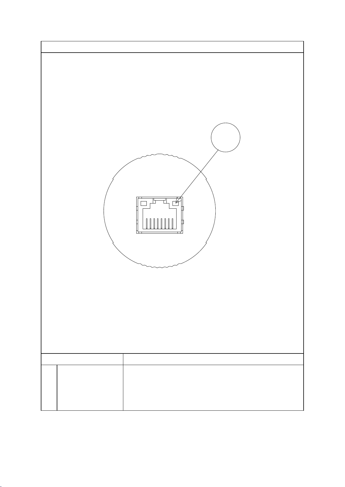
In a vacuum, the filament is heated and an accurate resistance value cannot be
measured, so always measure at atmospheric pressure.
Ensure that the connection cable to each pin does not contact other pins or the case.
Use caution not to mistake the pin assignments. If the wiring is wrong, there is a risk of
damage to this unit and to devices connected to this unit and a risk of fire.
Do not wire this unit cable in proximity or parallel to electrical lines, power lines,
high voltage lines, or high frequency lines. There is a risk of malfunction.