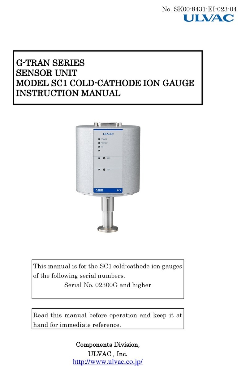
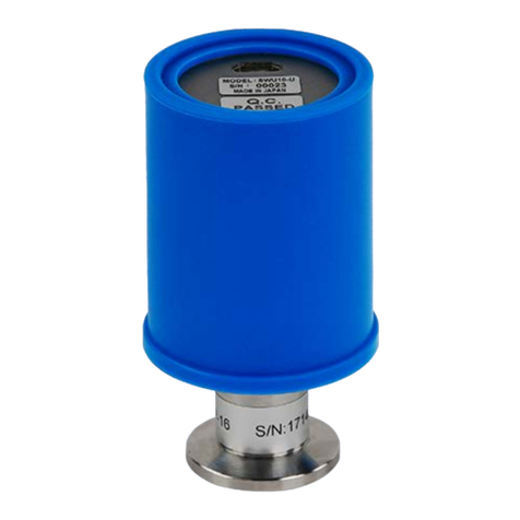
Ulvac G-TRAN SW100-A User manual

SK00-9663-EI-003-00
I
Vacuum Gauge
Instruction Manual
G-TRAN series
Pirani Vacuum Gauge Sensor Unit
Analog Output Type SW100-A
Serial Communication Type SW100-R
This instruction manual describes the serial numbers after
the following numbers.
SW100-A:S/N 00001~
SW100-R:S/N 00001~
Please be sure to read this before using this product.
Also, please keep it in a safe place so that you can use it
at any time.
ULVAC, Inc. Components Division
https://www.ulvac.co.jp/en/

SK00-9663-EI-003-00
II
Before using this product
Thank you for purchasing our product.
When you receive this product, first check that it is the same as your order and that
it is not damaged by transportation.
In order to use this product for a long time, please be sure to read this instruction
manual before installing, operating, inspecting, or servicing this product, and
matters related to safety precautions, specifications and operation methods of this
product. Please fully understand.
The copyright of the instruction manual belongs to ULVAC, Inc.
It is prohibited to copy any part of the instruction manual without our consent.
In addition, it is prohibited to disclose or transfer the instruction manual to a
third party without the written consent of our company.
Please note that the contents of the instruction manual are subject to change or
revision without notice due to changes in product specifications or product
improvements.
Saftety symbol marks
The warning display in this instruction manual contains a symbol mark for safety so
that you can understand the matters to be observed. The words used for the symbol mark
are used properly as follows.
*WARNING*
Failure
to follow this warning indicates a dangerous situation that
could result in death or serious injury.
Work that ignores this warning part may cause serious damage to the
life of the worker or factory equipment (including this product).
*CAUTION*
Indicates
a risk situation that could result in minor or moderate
injury if this caution is not followed.
If you ignore this caution, you may cause minor injuries to the
operator, or you may break the equipment or make adjustments.
Note
Although there is no direct
danger, it describes what you need to know
for the safety of the operator or for the correct and safe use of the
device.

SK00-9663-EI-003-00
III
Safety precautions
Please be sure to read the instruction manual and the following safety precautions in
order to use the G-TRAN series sensor unit (hereinafter referred to as "this unit")
safely.
*WARNING*
Repair
For repairs, etc., contact the place of purchase, our company, or the
network destination described in the instruction manual.
*WARNING*
Power cut off
If the instrument is damaged, turn off the power immediately.
Continued use may cause fire or electric shock.
*WARNING*
Power cut off
If this unit generates abnormal heat, emits smoke, or has a strange
odor, turn off the power immediately. Continued use may cause a fire.
*WARNING*
Power supply voltage
Before turning on the power, check that the working voltage of this
unit and the power supply are correct. Connecting the wrong power
supply may damage this unit and the devices connected to this unit, or
cause a fire. In particular, do not apply a voltage exceeding DC30V.
The overvoltage category is categoryI.
*WARNING*
Power supply
Be sure to connect this unit to a power supply or evaluation unit
that conforms to the ground-protected safety ultra-low voltage
standard (EN61010 SELV-E). Also, attach a fuse to the connection.
*WARNING*
Power supply lightning surge compatible
For the power supply, use a power supply that supports lightning
surges. If it is not compatible with lightning surges, it may damage
this unit and the devices connected to this unit, or cause a fire.
*WARNING*
Protective ground
Be sure to electrically connect this unit to a grounded vacuum
chamber. Use a conductive metal clamp for the NW flange. If it is not
grounded properly, not only will it not show the correct pressure, but
it may also damage this unit and the equipment connected to it, or
cause a fire.
If insulation with the vacuum chamber is required, ground the case
part (D-sub connector shell part) to D type (3types).
*WARNING*
Wiring confirmation
Make sure that the connection cable to each pin does not come into
contact with other pins or cases. Also, be careful not to make a
mistake in the pin sign. Incorrect connection may cause damage to this
unit and the devices connected to this unit, or cause a fire.
*WARNING*
Check power polarity
Before turning on the power, check that the polarities of the working
voltage and supply voltage of this unit match. Connecting the wrong
polarity may cause damage to this unit and the equipment connected to
this unit, or cause a fire.

SK00-9663-EI-003-00
IV
*WARNING*
Power on
After connecting the sensor, display, PLC (programmable logic
controller), cable, etc. to this unit, turn on the power. Doing so may
damage this unit or the equipment connected to this unit or cause a
fire. In addition, the filament of the sensor may be disconnected.
*WARNING*
Excessive pressure in the vacuum chamber
Do not connect to a place where the pressure inside the sensor
exceeds atmospheric pressure. If the pressure inside the sensor
exceeds atmospheric pressure, the sensor will be damaged and the
sensor will pop out from the connection and cause harm to the
surroundings including the human body. When the pressure exceeds the
atmospheric pressure, install an isolation valve so that the pressure
inside the sensor does not exceed the atmospheric pressure.
*WARNING*
Disassembly prohibited
Do not disassemble this unit. It may cause a fire or electric shock.
If disassembled, the operation cannot be guaranteed.
*WARNING*
No modification
Do not modify this unit. It may cause a fire or electric shock. If
you modify it, we cannot guarantee its operation.
*WARNING*
Usage environment
Use this instrument within the environment specified in the
specifications.
*WARNING*
Usage environment (condensation, humidity, temperature)
Do not use it in a place where this unit is exposed to water or where
the humidity is high and condensation occurs. If water gets inside
this unit, it may cause a malfunction, electric leakage, or fire.
Also, using it outside the specified temperature range may cause a
malfunction or fire.
*CAUTION*
Precautions when laying cables
When laying a communication transmission line in a device, make sure
that the wiring is not close to or parallel to the power line, power
line, high voltage line, high frequency line, etc. It may cause a
malfunction.
*CAUTION*
Ensuring ventilation
Do not put the instrument in a closed container, and be sure to
install it in a well-ventilated place. If sealed, the temperature of
the
electronic components inside the power supply will rise, which may
shorten the service life.
*CAUTION*
Usage environment
When exposed to chemically active gas such as halogens and halogen-
based gases, problems such as disconnection of filaments and changes
in pressure characteristics occur. When using in such an environment,
install an isolation valve between this unit and the vacuum chamber to
protect it from exposure to these gases as much as possible.

SK00-9663-EI-003-00
V
*CAUTION*
Usage environment
When exposed to accumulated gas such as rotary pump oil mist and CVD
(Chemical Vapor Deposition) raw material gas, problems such as
disconnection of filaments and changes in pressure characteristics
occur. When using in such an environment, install an isolation valve
between this unit and the vacuum chamber, and seal the isolation valve
so that it is not exposed to these gases as much as possible.
*CAUTION*
Moisture and deposits
If there are many deposits that gradually evaporate, such as water
and organic matter, in the sensor, it will affect the pressure
accuracy and response speed on the zero point side. Please consider
the installation location and method so that deposits do not adhere.
*CAUTION*
Influence of magnetic field
Due to the influence of a magnetic field of 0.01T (100G), the
pressure indication on the atmospheric pressure side is affected by
about 10%. If this unit is affected by a magnetic field, install a
magnetic shield.
*CAUTION*
Temperature fluctuation
According to the measurement principle of pirani vacuum gauge, the
ambient temperature of the sensor affects the measured value. If the
ambient temperature deviates significantly from the temperature at the
time of calibration (about 25℃), adjust the atmospheric pressure and
zero point.
*CAUTION*
Contact capacity
The capacity of the externally installed contacts should be equal to
or higher than the input power supply voltage or DC30V or higher.
*CAUTION*
Contact leak current
Pay attention to the leak current of the contacts. If a current of
0.1mA
or more flows between the input signal pin and the GND terminal,
it may be treated as if the signal was input.
*CAUTION*
Noise resistance of remote host
For remote hosts such as personal computers and PLCs, use an
isolation type with high noise resistance. It may cause malfunction or
failure.
*CAUTION*
Foreign matter intrusion
Protect the inside of this unit and sensor from the openings of
foreign matters such as metals and flammable materials. It may damage
the equipment or cause a fire.
*CAUTION*
Gas species dependence
The pressure value and accuracy of this unit differ depending on the
type of gas to be measured. The accuracy of this unit is when
measuring nitrogen gas, so be careful not to exceed the pressure when
using gas other than nitrogen.

SK00-9663-EI-003-00
VI
*CAUTION*
Check for pressure indication
Immediately after starting use, check the pressure indication,
especially the pressure on the atmospheric pressure side and the zero
point side. If necessary, adjust the atmospheric pressure and zero
point.
Due to the principle of pirani vacuum gauge, the pressure indication
is affected by the environmental temperature. In addition, there is a
possibility that the atmospheric pressure and zero point adjustment
will shift due to vibration during transportation.
*CAUTION*
Leak test
When the sensor is replaced or removed, perform a leak test. It may
be leaking due to the impact on the pin part.
*CAUTION*
Lifetime parts
An aluminum electrolytic capacitor is used for the electric circuit
inside this unit. Generally, aluminum electrolytic capacitors have a
limited life, and the higher the ambient temperature, the shorter the
life. To prevent damage to the equipment, we recommend that you
perform maintenance about once every three years.
*CAUTION*
Impact
Do not give a shock to this unit. The impact may cause the filament
to disconnection, the sensor to leak, or the mounting part to be
damaged.
*CAUTION*
Shipping packing
When transporting this unit, return it to the factory default state.
It may be damaged if shipped unpacked or attached to the device.
*CAUTION*
Waste
When disposing of this unit, dispose of it according to the
regulations of each local government. In particular, the sensor used
in an atmosphere that may pose a danger to the human body should be
processed through a professional processor.
Customers are responsible for the cost of disposal.

SK00-9663-EI-003-00
VII
Revision history
Date
Number
Reason
2022/10/3 00 First edition

SK00-9663-EI-003-00
VIII
Contents
BEFORE USING THIS PRODUCTS........................................ II
SAFETY SYMBOL MARKS............................................... II
SAFETY PRECAUTIONS................................................III
REVSION HISTORY...................................................VII
CONTENTS.........................................................VIII
1. SPECIFICATION ...................... 10
1.1. UNPACKING AND QUANTITY CHECK......... 10
Included items ............. 10
Items that need to be ordered
separately ......................... 11
1.2. SW100 STANDARD SPECIFICATIONS ....... 11
2. HANDLING PRECAUTIONS ............... 14
2.1. PRECAUTIONS ON OPERATING ENVIRONMENT .. 14
2.2. PRECAUTIONS ON POWER SUPPLY.......... 15
2.3. PRECAUTIONS ON INSTALLATION OF THIS UNIT 15
2.4. PRECAUTION ON USAGE ................ 17
2.5. CHECK ITEMS IMMEDIATELY AFTR THE START OF
USE ............................... 17
3. NAME OF EACH PART AND EXPLANATION OF
FUNCTION................................ 18
3.1. SW100 CONTROLLER SECTION ........... 18
3.2. SW100 FRONT PANEL SECION ........... 19
3.3. I/O CONNECTOR ANALOG OUTPUT TYPE SW100-
A ............................... 20
3.4. I/O CONNECTOR SERIAL COMMUNICATION TYPE
SW100-R .............................. 21
4. POWER SUPPLY INTERNAL CIRCUIT....... 22
5. SIGNALS ............................ 23
5.1. PRESSURE SIGNAL OUTPUT............. 23
Pressure conversion formula 23
Measured value output in each
state ........................... 23
5.2. I/O OUTPUT SIGNAL ................. 24
Sensor error signal ........ 24
Setpoint operation signal ...24
5.3. I/O INPUT SIGNAL (ANALOG OUTPUT TYPE
SW100-A ONLY) ..........................25
6. SETPOINT SETTINGS ...................26
6.1. SETPOINT ON/OFF PRESSURE............26
7. HOW TO USE SERIAL COMMUNICATION (SERIAL
COMMUNICATION TYPE SW100-R ONLY).........27
7.1. COMMUNICATION SPECIFICATIONS..........27
7.2. SETTINGS..........................27
Connection diagram ..........27
Address settings ............28
Baud rate settings ..........28
7.3. STANDARD DATA FORMAT ................29
Command list ................29
When receiving is normal ....29
When receiving is abnormal. .29
7.4. COMMAND ..........................30
Reading measurement values and
status ............................30
Zero point adjustment
command ............................30
Atmospheric pressure
adjustment command ..................30
Zero point, atmospheric
pressure adjustment clear command ...30
Reading status ..............30
Reading software version ....31
Reading setpoint1 setting
value ............................31
Reading setpoint2 setting
value ............................31

SK00-9663-EI-003-00
IX
Writing setpoint1 setting
value ........................... 31
Writing setpoint2 setting
value ......................... 31
7.5. CHECKSUM......................... 32
7.6. STATUS .......................... 33
SH (Higher status) ......... 33
SL (Lower status) .......... 33
7.7. ASCII CODE TABLE ................. 34
8. ZERO POINT ADJUSTMENT AND ATMOSPHERIC
PRESSURE ADJUSTMENT..................... 35
8.1. ADJUSTING METHOD .................. 35
Zero point adjustment ...... 35
Atmospheric pressure
adjustment ......................... 35
8.2. CHECKING THE COMPLETION OF ADJUSTMENT . 36
8.3. ADJUSTMENT CLEAR .................. 36
8.4. MEMORY FUNCTION ................... 36
9. OUTPUT (MEASURED OUTPUT VOLTAGE
COMPATIBILITY).......................... 37
9.1. SW1 SERIES COMPATIBILITY............ 37
9.2. SP1 COMPATIBILITY ................. 38
9.3. OTHER COMPATIBILITY ................ 39
PSG compatibility .......... 39
APG compatibility .......... 40
9.4. I/O CONNECTOR ANALOG OUTPUT TYPE SP1,
PSG, APG.............................. 41
10. SENSOR REPLACEMENT ............... 42
10.1. TOOLS ......................... 42
10.2. REMOVAL OF SENSOR ............... 42
10.3. MOUNTING THE SENSOR.............. 42
10.4. LEAK TEST...................... 42
10.5. ADJUSTMENT AFTER REPLACEMENT OF SENSOR42
11. HOW TO USE UL-MOBI ............... 43
11.1. FUNCTION....................... 43
11.2. WINDOWS VERSION UL-MOBI ......... 44
Usage environment ........ 44
Download/install ..........45
How to use ................45
11.3. ANDROID VERSION UL-MOBI ..........50
Usage environment .........50
Download/install ..........50
How to use ................50
11.4. STATUS COMMENT..................56
12. TROUBLESHOOTING ...................57
12.1. TROUBLESHOOTING ..................57
12.2. CONFIRMATION OF FILAMENT AND TEMPERATURE
SENSOR DISCONNECTION ......................63
12.3. INSULATION BETWEEN THE SENSOR PIN AND
CASE ..............................63
13. TECHNICAL REPORT ..................64
13.1. GAS SPECIE/HUMIDITY DEPENDENCE......64
13.2. ZERO POINT ADJUSTMENT AND ATMOSPHERIC
PRESSURE ADJUSTMENT .......................65
13.3. SCHEDULED ADJUSTMENT ..............65
14. WARRANTY ..........................67
15. EC DECLARATION OF CONFORMITY ......69
16. UK DECLARATION OF CONFORMITY ......70
17. CERTIFICATE OF DECONTAMINATION ....71
18. DRAWINGS ..........................72
18.1. SW100-A/R DIMENSIONS............72
18.2. SENSOR DIMENSIONS ................73
18.3. DISPLAY UNIT CABLE ...............74

SK00-9663-EI-003-00
10
1. Specification
Pirani vacuum gauge sensor unit SW100 is a vacuum gauge that can measure low vacuum
pressure by connecting a dedicated sensor (SWP series).
The SW100 is the next model to the conventional model SW1, and the SW100-A is compatible
with SW1-1 and the SW100-R is compatible with SW1-2. (For other compatibility, refer to
Chapter 9 of this manual.)
The following two types of interfaces are available, and you can select the
specifications according to the usage conditions.
Analog output type : SW100-A (next model of SW1-1)
Serial communication type : SW100-R (next model of SW1-2)
(Hereinafter, the description of SW100 only is a collective name for SW100-A and SW100-
R.)
The I/O connector of SW100 uses D-sub15pin and USB Type-C.
Settings of SW100 are made using the dedicated Windows/Android application "UL-MOBI".
※USB Type-C can be connected to a Windows/Android device with UL-MOBI installed using
a USB cable, and UL-MOBI can be used for monitoring and settings. For the UL-MOBI
download method and operation method, refer to Chapter 11 of this manual.
※Settings that require UL-MOBI are setpoint, OUTPUT, ADDRESS, BAUD RATE, and CHECKSUM.
For details, refer to Chapter 7 of this manual and Chapter 11 of this manual.
※Windows/Android devices and USB cables are not included.
※UL-MOBI for Windows requires a device driver installation. UL-MOBI can be started
if the device driver is not installed, but Windows cannot recognize the connection
even if the SW100 is connected to the Windows device with a USB cable. (Unknown
device is displayed in the device manager.) If UL-MOBI does not work on a Windows
device, check Section 11.2.2 3) and install the device driver.
1.1. Unpacking and quantity check
When the product arrives, immediately unpack it and check the product.
Please check if there is any damage during transportation and if the accessories are
attached in just proportion.
Included items
Pirani vacuum gauge sensor unit SW100 1pc.
Sensor for SW100 (shipped with the SW100 main unit attached) 1pc.
Quick manual (regular paper) 1copy

SK00-9663-EI-003-00
11
Items that need to be ordered separately
①
Connector for
SW100
D-sub15pin connector (female),
M2.6mm screw
※Unwired
Calibration
certificate
General calibration test report
JCSS calibration certificate
Inspection report
Traceability
certificate
Display unit Model ISG1
(using DC24V power supply)
②
Display cable Between SW100 and display unit
2m, 5m, 10m
③
Sensor for SW100
※Refer to Section
18.2
SWP-16(NW16), SWP-25(NW25),
SWP-R1/8(R1/8), SWP-P18(φ18Tube),
SWP-P15(φ15Tube), SWP-CF16(ICF034),
SWP-1S(ASME BPE sanitary1”)
1.2. SW100 standard specifications
Name Pirani vacuum gauge sensor unit
Model Analog output tyoe Serial communication type
Type SW100-A SW100-R
Compatible sensor
※Selected one is
included
※Refer to Section
18.2
Sensor for SW100: 1本
SWP-16(NW16), SWP-25(NW25), SWP-R1/8(R1/8),
SWP-P18(φ18Tube), SWP-P15(φ15Tube),
SWP-CF16(ICF034), SWP-1S(ASME BPE sanitary1”)
Measurement pressure
range (N2) 5.0×10⁻²Pa to 1.0×10+5Pa
Measurement accuracy※1
(N2)
1×10⁻¹Pa to 1×10+4Pa :±10%
5×10⁻²Pa to 1×10⁻¹Pa
1×10+4Pa to 1×10+5Pa :±20%
Repeatability 1×10⁻¹Pa to 1×10+4Pa :±2%
Measuring gas type Indicated pressure as sensitivity to N2gas
Sampling time 5times in 60msec moving average
Measured value output
Output voltage : DC 0V to 10V
Pressure indication: DC 1.7V to 8.0V
log output DC 1.0V/digit
Update time 50msec
Resolution 3mV
Error ±3mV
Output impedance 10Ω
Adjustment Zero point/atmospheric pressure adjustment,
adjustment clear
Control input signal
Zero point/atmospheric
pressure adjustmene,
adjustment clear
Operates with open collector
input, negative logic
①
②
③

SK00-9663-EI-003-00
12
Control output signal
Sensor error signal, setpoint1/2
Open collector output, negative logic
Rating: 30VMAX, 50mAMAX, 70mW
Communication
D-sub15pin
USB Type-C
※USB Type-C can only be used for communication using UL-
MOBI.
Serial
communication
RS-232C/RS-485
Communication
speed 9600/19200/38400bps
Memory function Back pu with EEPROM
LED display
POWER/ERROR: Power, error LED
SET-1 : Setpoint1 LED
SET-2 : Setpoint2 LED
Sensor material
Filament: Pt
Others : SUS304 (SWP-1S: SUS316L/Ra<0.5), FeNiCo, Ni, Au,
Glass, Ceramic
Sensor breaking
pressure
2.0×10
+5
Pa (absolute pressure)
※Please consider the breaking pressure of flanges and
clamps separately.
Operating temperature
range 10℃to 40℃
Operating humidity
range 15% to 80% (no condensation)
Storage temperature -20℃to 65℃ (no energization, no condensation)
Sensor heating
temperature
Sensor only 150℃ (without SW100)
※When heating, deviations from specifications, such as
accuracy, is observed.
※The operating temperature range of SW100 is 5℃to 40℃.
Mounting position Free
IP protection class IP30
Power supply voltage
Rated voltage: DC 24V
Voltage fluctuations: DC 14V to 30VMAX (-42%/+25%)
(ripple, noise<1%)
※Power supply voltage at the SW100 connector end
Steady state : 2.0W
When power turned on: 4.8W
Overvoltage category: Category1
※Connect to circuits that has measures to limit the
transient overvoltages to a suffisiently low level.
Corresponding standard CE standard, UKCA standard
I/O connector
D-sub15pin connector (pin), M2.6mm screw
USB Type-C
※USB Type-C can only be used for communication using UL-
MOBI.
Weight SW100 only: approx.105g
Dimensions SW100 only: approx.48mm×30mm×74mm ※Refer to Section 18.1

SK00-9663-EI-003-00
13
Sensor
※Refer to
section
18.2
Model SWP-16 SWP-25 SWP-
R1/8 SWP-P18 SWP-P15 SWP-
CF16 SWP-1S
Innner
volume 7.3cm37.8cm37.6cm313.9cm3
10.0cm3
11.3cm38.2cm3
Weight 45g 48g 44g 43g 30g 60g 95g
accuracy※1:The accuracy after atmospheric pressure and zero point adjustment. Please
carry out atmospheric pressure and zero point adjustment before use
especially. Moreover, since calibration gas is N2, when other gas is measured,
be careful of an error of measurement.

SK00-9663-EI-003-00
14
2. Handling precautions
*CAUTION*
Please check this chapter before you start using this unit.
2.1. Precautions on operating environment
Usage environment
Use this unit within the environment specified in the specifications.
Usage environment
Do not use it in a place
where this unit is exposed to water or where the humidity
is high and condensation occurs. If water gets inside thid unit, it may cause a
malfunction, electric leakage, or fire.
Ensuring ventilation
Do not put this unit in a closed container, and be sure to install it in a well-
ventilated place. If sealed, the temperature of the electronic components inside the
power supply will rise, which may shorten the service life.
Excessive pressure in the vacuum chamber
Do not connect to a place where the pressure
inside the sensor exceeds atmospheric
pressure. It may cause harm to the surroundings including the human body, such as
damage to the sensor or popping out of the sensor from the connection. When the
pressure exceeds the atmospheric pressure, install an is
olation valve so that the
pressure inside the sensor does not exceed the atmospheric pressure.
Use in a corrosive gas atmosphere
When exposed to corrosive gas or chemically active gas such as halogen or halogen-
based gas, problems such as disconnection of
filaments and changes in pressure
characteristics occur. When using in such an environment, install an isolation valve
between this unit and the vacuum chamber to protect it from exposure to these gases
as much as possible.
Use in a CVD gas atmosphere, etc.
When exposed to CVD (Chemical Vapor Deposition) raw material gas or gas that
accumulates such as oil mist of rotary pumps, problems such as disconnection of
filaments and changes in pressure characteristics occur. When using in such an
environment, in
stall an isolation valve between this unit and the vacuum chamber to
protect it from exposure to these gases.
Moisture and deposits
If there are many deposits such as water and organic matters that gradually evaporate
in the sensor, it will affect the
pressure accuracy and response speed on the vacuum
side in particular. Please consider the installation location and method so that
deposits do not adhere.
Influence of magnetic field
Due to the influence of a magnetic field of 0.01T (100Gauss), the press
ure indication
on the atmospheric pressure side is affected by about 10%. If this unit is affected
by a magnetic field, install a magnetic shield.
Temperature fluctuation
According to the measurement principle of pirani vacuum gauge, the ambient
temperature
of the sensor affects the measured value. Pay attention to the mounting position so
that the ambient temperature does not deviate significantly from the temperature at
the time of calibration (about 25℃).

SK00-9663-EI-003-00
15
Influence of electrons, ions, etc.
If
there is a strong source of electrons or ions nearby, not only will the correct
pressure not be measured, but it may also cause damage or malfunction of this unit.
Please be careful about the mounting position so that it will not be affected by
electrons or ions.
Foreign matter intrusion
Protect the inside of this unit from the opening to prevent foreign matter such as
metals and flammable materials from entering.
Impact
Do not give a shock to this unit. The impact may cause the filament to disconnection,
the sensor to leak, or the mounting part to be damaged.
2.2. Precautions on power supply
Power supply
Be sure to connect this unit to a power supply or evaluation unit that conforms to
the ground-protected PELV standard (EN/IEC 60204-
1). Also, attach a fuse to the
connection. If the voltage supplied to this unit is less than DC
14V, the correct
pressure will not be indicated.
Precautions when laying cables
Make sure that the connection cable to each pin does not come into
contact with other
pins or cases. Also, be careful not to make a mistake in the pin sign. Incorrect
connection may cause damage to this unit and the devices connected to this unit, or
cause a fire.
Power supply voltage
Before turning on the power, check
that the working voltage of this unit and the power
supply are correct. Connecting the wrong power supply may damage this unit and the
devices connected to this unit, or cause a fire. In particular, do not apply a voltage
exceeding DC 30V.
Power on
Turn
on the power after connecting all the sensor, display, evaluation unit, cable,
etc. to this unit. Doing so may damage this unit or the equipment connected to this
unit or cause a fire. In addition, the filament of the sensor may be disconnected.
Voltage drop of power cable
Due to the voltage drop of the power cable, the supply voltage to this unit may be
less than DC
14V. Be especially careful when the thickness of the cable is thinner
than AWG24 line.
Recommended cable length with an environmental temperature of 20℃
when the DC supply
power supply voltage is DC 24V.
AWG26: 10m, AWG24: 20m, AWG22: 30m
2.3. Precautions on installation of this unit
Protective ground
Be sure to electrically connect this unit to a grounded vacuum chamber. Use a
conductive metal
clamp for the NW flange. If it is not grounded properly, not only
will it not show the correct pressure, but it may also damage this unit and the
equipment connected to it, or cause a fire. When insulating from the vacuum chamber,
ground the case part (D-sub connector shell part) to D type (3types).

SK00-9663-EI-003-00
16
Temperature fluctuation
According to the measurement principle of p
irani vacuum gauge, the ambient temperature
of the sensor affects the measured value. If the ambient temperature deviates
significantly from the temperature at the time of calibration (about 25℃), adjust the
atmospheric pressure and zero point.
Influence of magnetic field
Due to the influence of a magnetic field of 0.01T (100G) on this unit, the pressure
indication on the atmospheric pressure
side is affected by about 10%. If this unit is
affected by a magnetic field, install a magnetic shield.
Fixing method
Fix the cable so that the connection part of the cable is not applied as much as
possible. Make sure to insert the unit cable and tighten the connector fixing screw.
Life of female connector
The female connector used for the fitting part with the sensor of this unit has a
limited life. The life of the sensor will be significantly shortened due to poor
contact of the connector, etc., so
please refrain from inserting and removing the
connector as many times as possible. Also, tighten the sensor fixing screw firmly so
that the connector is not overloaded.
Vibration
Since the filament of the pirani sensor is as thin as φ25μm, avoid using it
in a
place with a lot of vibration as much as possib
le. Also, the biggest cause of
disconnection is due to mechanical shock, so please be careful about the installation
location and handling.
Mounting position
Pressure measurement measures the static
pressure at the position where the sensor
is connected. When installing in an environment where there is a flow in the vacuum
system, a source of emitted gas/electrons, a strong source of ions, or a magnetic
field, pay attention to the selection of the mea
surement position and install it in a
position where there is little influence.
Gas flow in the measurement system
Pressure measurement measures the static pressure at the position where the sensor
is connected. Make sure that the sensor mounting opening
surface is parallel to the
gas flow. In particular, make sure that gas does not enter the sensor in a beam shape.
Also, pay attention to the mounting position so that it will not be affected by outgas.
Outgas
Use an O-ring with less outgas when attaching the sensor
. If a material with a large
amount of outgas such as a rubber tube or grease is used to connect the sensor
, it
will cause an error and shorten the service life.
Since it is vulnerable to vibration in the X/Y
direction, install it so that vibration is not
applied in the X/Y direction.
Vertical direction
Gas flow direction

SK00-9663-EI-003-00
17
2.4. Precaution on usage
Impact
If this unit is dropped or installed in a place with large vibrations, the impact or
vibration may cause disconnection of the
filament of the sensor or damage to this
unit.
Measurement
Please go after aging for 20minutes or more.
Shipping packing
When transporting this unit, return it to the factory default state. It may be
damaged if shipped unpacked or attached to the device.
Repair
For repairs, etc., please contact the place of purchase, our company, or the network
destination described in the instruction manual.
Waste
When disposing of this unit, dispose of it according to the regulations of each local
government.
In
particular, the sensor used in an atmosphere that can be dangerous to the human
body should be processed through a professional processor.
The customer is responsible for the cost of disposal.
2.5. Check items immediately aftr the start of use
Gas species dependence
The pressure value and accuracy of this unit differ depending on the type of gas to
be measured. The accuracy of this unit is when measuring nitrogen gas, so be careful
not to exceed the pressure when using gas other than nitrogen.
Check for pressure indication
Immediately after use, check the pressure indication, especially the pressure on the
atmospheric pressure side and the zero point side. If necessary, adjust the atmospheric
pressure and zero point. Due to the principle of pirani vacuum
gauge, the pressure
indication is affected by the environmental temperature, etc. In addition, there is a
possibility that the atmospheric pressure and zero point adjustment will shift due to
vibration during transportation.

SK00-9663-EI-003-00
18
3. Name of each part and explanation of function
3.1.
SW100 controller section
Diagram of SW100 controller section
Name
Function
①I/O connector I/O connector(D-sub15pin connector(pin)、M2.6mm screw)
②Mating screw Mating screw (M2.6mm screw) for I/O connector fixing.
③Sensor fixing screw
Screw dor fixing sensor (M3mm screw)
④Lid fixing screw Screw for fixing the case lid (M3mm screw)
⑤USB TYPE-C USB connector to connect a Windows/Android device when using
UL-MOBI.
①
②
③
④
⑤

SK00-9663-EI-003-00
19
3.2.
SW100 front panel secion
Diagram of SW100 front panel section
Name
Function
①POWER/ERROR LED
Lights blue when this unit is operating normally.
Lights red when the filament of the sensor is disconnection.
Flashes blue when zero point adjustment or atmospheric
pressure adjustment is performed. ※Refer to Section 8.2
②SET-1 LED Lights when set point1 is in operation.
③SET-2 LED Lights when set point2 is in operation.
④ADJ switch It is a switch for atmospheric pressure adjustment, zero
point adjustment, and adjustment clear.
①
②
③
④

SK00-9663-EI-003-00
20
3.3.
I/O connector Analog output type SW100-A
Analog output type SW100-A I/O connector
Pin layout(D-sub15pin connector(male) M2.6mm screw)
Terminal
number
This unit
Function
1 Power supply Power supply for driving this unit DC 14V to 30V
2 Sensor error Outputs signal when the filament is
dsconnected, etc. Lo output
3 Setpoint1 Outputs signal when setpoint1 is
operating. Lo output
4
5 Input adjustment Input sugnal when adjusting atmospheric
pressure and zero point. Lo input
6
7
8 Output pressure
signal Output pressure signal DC 0V to 10V
9 Power supply GND The ground of power supply for driving
this unit.
10
11 Setpoint2 Outputs signal when setpoint2 is
operating. Lo output
12
13
14
15 Signal GND Ground for output signal
Case Frame ground Grounbd of frame
*CAUTION*
Wiring
Do not wire the shaded area as it is used in the internal circuit.
※When SP1, PSG, and APG are selected as OUTPUT, it is different from the above pin
layout.
For details, refer Chapter 9 of this manual.
8
1
915
This manual suits for next models
1
Table of contents
Other Ulvac Measuring Instrument manuals

Ulvac
Ulvac G-Tran Series User manual

Ulvac
Ulvac AxTRAN ISX2 User manual

Ulvac
Ulvac SPU User manual

Ulvac
Ulvac GP-1G User manual

Ulvac
Ulvac G-Tran Series User manual

Ulvac
Ulvac G-Tran Series User manual

Ulvac
Ulvac MBD Series User manual

Ulvac
Ulvac MBD-D User manual

Ulvac
Ulvac G-Tran Series User manual

Ulvac
Ulvac GP-1000G User manual