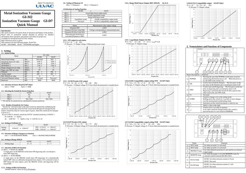
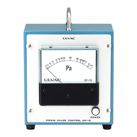
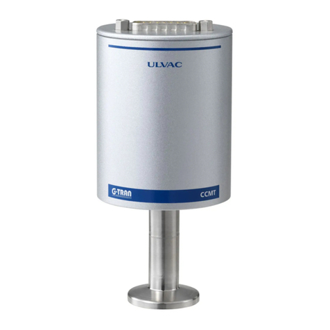
Ulvac AxTRAN ISX2 User manual

No.SK00-7200-EI-003-08
AxTRAN
MODEL ISX2
EXTREME-HIGH VACUUM GAUGE
INSTRUCTION MANUAL
This manual is for ultra-high vacuum
gauges of serial
numbers 00100 and higher.
Read this manual carefully before using this gauge and keep
it at hand for immediate reference.
When used by Torr, the following conversion equations shall be used.
1[Torr]=1.3332×10²[Pa]
1[Pa]=7.5006×10⁻³[Torr]
Components Division,
ULVAC, Inc.
2500 Hagisono, Chigasaki City, Kanagawa Prefecture, Japan 253-8543
http://www.ulvac.co.jp/

I

II
Before Use of This Gauge
Thank you for purchasing this ULVAC product.
Upon receipt of the product, verify that is the correct model ordered and that it has not been damaged during
transport.
Read this instruction manual before installing, operating, inspecting, or
maintaining the product and fully understand the safety precautions,
specifications and operating procedures regarding the product.
The copyright of this instruction manual is held by ULVAC, Inc.
You are prohibited from copying any portion of this instruction manual without
the consent of ULVAC Inc.
You are also prohibited from disclosing or transferring this instruction manual to
third parties without the express written consent of ULVAC Inc.
The contents described in this instruction manual are subject to change without
prior notice because of changes in specifications or because of product
improvements.
Safety Denotations
Safety symbols are used throughout this instruction manual to call the
operator's attention to safety. The terminology used in safety symbols is
classified below.
Indicate status of urgency of danger when failure to comply with DANGER
results in serious personal injury or death
The work ignoring this warning will lead to serious damage to human life or
factory facility (including this equipment) at a high probability.
Indicate status of danger when failure to comply with WARNING results in
serious worker’s injury or death.
The work ignoring this warning will cause possibility leading to serious
damage to human life or factory facility (including this equipment)
Indicate status of danger when failure to comply with WARNING results in
minor injury or moderate damage.
The work ignoring this warning will cause possibility leading to minor damage
to worker or breakage to equipment or necessary to adjust.
Direct hazard is not existed, describe the necessity to know
from the viewpoint of worker’s safety or correct and safe operation of
equipment
✔Note

III
Safety Precautions
For safe use of this gauge, be sure to read this manual and the following safety precautions.
Turn off power.
If the gauge is damaged, immediately turn off the power. Otherwise, fire or
electric shock can result. For safety reasons, contact your local ULVAC
representative or ULVAC, Inc.
Turn off power.
Ifthe gauge gets unusually hot or gives offsmoke or unusual smell, immediately
turn off the power. Otherwise, fire can result. For safety reasons, contact
your local ULVAC representative or ULVAC, Inc.
Turn off power.
Whenever you touch or may touch the sensor connector on the front panel, turn
off the power to the gauge. A grid voltage of 100 VDC is applied to the sensor
connector. If you touch it when the filament is turned on, you will get electric
shock.
Beware of high temperature.
Do not touch the sensor head surface, which is very hot during and immediately
after operation. If you touch it, you may get burned.
Don′t disassemble.
Do not disassemble the vacuum gauge.
Don′t modify.
Do not modify the vacuum gauge. If it is modified, its action is not warranted.
Also fire or electric shock can result.
Be cautious with operating environment.
Do not connect the sensor head to an environment where pressure exceeds
atmospheric pressure. If the pressure in the sensor head exceeds atmospheric
pressure, the sensor head will be damaged and the sensor head will pop out from
the connectio
n, causing damage/injury to human body and others. In that
event, provide an isolation valve or other so that the pressure in the sensor head
does not exceed atmospheric pressure.
Check line voltage
Before turning on the power, make sure the operating voltage and supply voltage
polarities are in agreement. If the gauge is connected to an incorrect power
source, this gauge and equipment connected to it may be damaged or fire can
result.
Ensure ventilation.
Do not plug the port for the fan and air vents. If it is plugged, heat will be
contained inside, resulting in damage. The vacuum gauge will not indicate a
normal value either.
Be cautious with operating environment.
Do not use the gauge where it may splashed with water. If it is wetted, trouble,
earth leakage or fire can result.
Keep out foreign matter.
If metal fragments or combustible material are admitted into the gauge through
an opening in the gauge, remove them. Also keep clear the connection
terminals on the front and top of the gauge. Otherwise, the vacuum gauge may
be damaged.
Beware of impact.
Do give an impact to the sensor head.

IV
Check connection
See to it that the cable does not come into contact with other conductive part.
Disposal
When discarding the vacuum gauge, comply with your local regulations.
Customer shall be responsible for the cost relating to disinstallation.
Be cautious with operating conditions
Use this gauge within the specified environment range.
Caution in repacking
When shipping the gauge, rep
ack it in the same way as on delivery. It is
shipped bare, it may be damaged.
Maintenance
Aluminum electrolytic capacitor and cooling fan are used for the electric circuit
in the sensor unit. Generally, the life expectancy of the aluminum electrolytic
capacity is limited and the higher the surrounding temperature, the shorter the
life. It is recommended to replace the aluminum electrolytic capacitor , cooling
fan
once every three years or at the time or repair or overhaul to prevent
components from being damaged.

V
Revision History
Date
No.
Reason
Jun.6,2007
01
Correction of errors
Jan.20,2008
02
Optional board details added
Nov.16,2009
03
Pressure unit conversion appendix
Pressure expression appendix
Supplementary explanation of current unit
delete
Nov.13,2013
04
・
Sensor material
・
Standard Accessories
・
WARRANTY
・EC DECLARATION OF CONFORTMITY
・
CERTIFICATE OF DECONTAMINATION
added
Oct.28,2016
05
Baking temperature added
Initial setting、Degassing Time、Recorder Selection、Offset
Adjustment、Interval Setting is change
Communication system Correction of errors
Communication cable PIN No Correction of errors
Reads action status
’
RS
’
added
Dec.2,2019
06
Grid voltage Correction of errors

Contents
Page
Before Use of This Gauge....................................................................................................................II
Safety Denotations ...............................................................................................................................II
Safety Precautions.............................................................................................................................. III
1. FEATURES OF ISX2.................................................................................................................. 1
2. SPECIFICATIONS AND COMPONENTS ................................................................................ 2
2.1. Standard Specifications ..................................................................................................... 2
2.2. Performance....................................................................................................................... 3
2.3. Utilities.............................................................................................................................. 3
2.4. Standard Accessories......................................................................................................... 3
2.5. Options .............................................................................................................................. 3
3. NOMENCLATURE AND FUNCTIONS OF COMPONENTS.................................................. 4
3.1. Operation Switch............................................................................................................... 4
3.2. Front Panel Lamps............................................................................................................. 5
3.3. Front Panel Measurement Value Display/Set Value Indicator.......................................... 6
3.4. Rear Panel.......................................................................................................................... 7
3.5. Accessory Connector......................................................................................................... 8
3.6. View when the Top Panel in Controller is opened............................................................ 9
3.7. View when the Bottom Panel in Controller is opened..................................................... 10
4. INSTALLATION....................................................................................................................... 11
4.1. Preliminary Operation ..................................................................................................... 11
4.2. Installation....................................................................................................................... 11
4.2.1. Installing the controller ................................................................................... 11
4.2.2. Installing the sensor head ................................................................................ 11
4.2.3. Connecting the controller and sensor head...................................................... 11
5. FLOW OF PROGRAM RUN .................................................................................................... 13
6. STARTING UP GAUGE (SUPPLY OF POWER).................................................................... 14
7. FRONT PANEL OPERATION ................................................................................................. 15
7.1. Filament ON/OFF............................................................................................................ 15
7.1.1. When pressure protection is activated............................................................. 16
7.2. Initialization..................................................................................................................... 17
7.3. Offset............................................................................................................................... 17
7.4. Degassing ON/OFF ......................................................................................................... 18
8. INITIAL SETTING.................................................................................................................... 19
8.1. Setting of Set Point 1 →See page 30.............................................................................. 20
8.2. Setting of Set point 2 →See page 30.............................................................................. 21
8.3. Sensitivity Factor Setting ................................................................................................ 22
8.4. Specific Sensitivity Factor Function Setting ................................................................... 23
8.5. Degassing Time Setting................................................................................................... 24
8.6. Filament No. Selection.................................................................................................... 25
8.7. Recorder Selection........................................................................................................... 25
8.8. Filter Setting.................................................................................................................... 26
8.9. Offset Adjustment Interval Setting.................................................................................. 27
8.10. Setting of Baud Rate........................................................................................................ 28
9. FUNCTIONS ............................................................................................................................. 29
9.1. Setting of Sensitivity Factor ............................................................................................ 29
9.1.1. Sensitivity factor.............................................................................................. 29
9.1.2. Setting of sensitivity factor.............................................................................. 29
9.1.3. Details of specific sensitivity........................................................................... 29
9.2. Set Point .......................................................................................................................... 30
9.2.1. What is the set point? ...................................................................................... 30
9.2.2. Setting of set point........................................................................................... 30
9.2.3. Internal processing .......................................................................................... 30
9.2.4. Set point activating conditions ........................................................................ 30
9.3. Degassing ........................................................................................................................ 31

9.3.1. What is degassing?.......................................................................................... 31
9.3.2. Setting the degassing time............................................................................... 31
9.3.3. Degassing operation ........................................................................................ 31
9.4. Filament Change.............................................................................................................. 32
9.4.1. Cautions in operation....................................................................................... 32
9.5. Changing over Recorder Output...................................................................................... 33
9.5.1. Setting of recorder mode ................................................................................. 33
9.5.2. Measurement value output in each status........................................................ 33
9.5.3. LIN output....................................................................................................... 33
9.5.4. LOG output ..................................................................................................... 35
9.5.5. Resolution and output period........................................................................... 36
10. EXTERNAL INPUTS/OUTPUTS.................................................................................. 37
10.1. Set Point Output .............................................................................................................. 37
10.2. Option Board ................................................................................................................... 38
10.3. EXT-I/O Connector......................................................................................................... 39
10.4. External Digital Output ................................................................................................... 40
10.5. External Control Input..................................................................................................... 43
10.6. Method of External Control............................................................................................. 45
11. HOW TO USE COMMUNICATION (RS-232C) .......................................................... 46
11.1. Communication Specifications........................................................................................ 46
11.1.1. Key specifications ........................................................................................... 46
11.1.2. Baud rate setting.............................................................................................. 46
11.1.3. Communication cable/connector..................................................................... 46
11.2. List of Commands ........................................................................................................... 47
11.3. Explanation of Command Action.................................................................................... 48
11.3.1. Changing over remote/local control ................................................................ 48
11.3.2. Reading the emission valid signal................................................................... 48
11.3.3. Control of filament.......................................................................................... 48
11.3.4. Control of degassing........................................................................................ 48
11.3.5. Reading the gauge status ................................................................................. 49
Setting sensitivity factor.................................................................................. 49
11.3.7. Setting specific sensitivity factor..................................................................... 49
11.3.8. Setting and reading the setpoint ...................................................................... 49
11.3.9. Reading the measured pressure value.............................................................. 50
11.3.10. Reading the external protection status............................................................. 50
11.3.11. Setting of filter................................................................................................. 50
11.3.12. Control of offset .............................................................................................. 50
11.3.13. Reading the controller status ........................................................................... 50
11.3.14. Error resetting.................................................................................................. 51
11.3.15. Setting the recorder output .............................................................................. 51
11.4. Cautions in Operation...................................................................................................... 51
12. TROUBLESHOOTING .................................................................................................. 52
12.1. Cause and measures where emission current doesn’t flow.............................................. 59
12.2. About the malfunction indication.................................................................................... 59
13. APPENDIX ..................................................................................................................... 60
13.1. Principles of Operation.................................................................................................... 60
13.1.1. Basic structure of ion gauge ............................................................................ 60
13.1.2. Problems of ion gauge..................................................................................... 61
13.1.3. Axial symmetric transmission (AT) gauge...................................................... 62
13.1.4. Micro current measurement............................................................................. 63
13.2. Types of Measurable Gas and Specific Sensitivity ......................................................... 64
14. APPENDIX: TEST MODE............................................................................................. 66
15. WARRANTY.................................................................................................................. 67
16. EC DECLARATION OF CONFORTMITY................................................................... 68
17. China RoHS Declaration ................................................................................................. 69
18. CERTIFICATE OF DECONTAMINATION ................................................................. 70
19. RELATED DRAWINGS ................................................................................................ 71
Attached Illustrations
Fig. 3-1 Operation switch panel ...........................................................................................................4
Fig. 3-2 Front panel lamps ...................................................................................................................5
Fig. 3-3 Front panel measurement value display/set value indicator ...................................................6
Fig. 3-4 Rear panel...............................................................................................................................7
Fig. 3-5 Set point, recorder output connector pin assignment..............................................................8
Fig. 3-6 View when top panel in controller is opened..........................................................................9
Fig. 3-7 View when the bottom panel in the controller is opened......................................................10
Fig. 4-1 Connection of controller (ISX2) and sensor head (X-11).....................................................12
Table 8-1 Factory Set Values .............................................................................................................19
Table 9-1 Measurement Value Output Status.....................................................................................33
Fig. 9-1 Recorder output graph (linear)..............................................................................................34
Table 9-2 Measured Pressure Value Table.........................................................................................35
Table 9-3 Measured Value Outputs....................................................................................................36
Fig. 10-1 Set point internal circuit......................................................................................................37
Input/output connector pin assignment .................................................................................................39
Fig. 10-2 Digital output internal circuit..............................................................................................40
Fig. 10-3 Data valid signal (strobe signal) actuating chart.................................................................41
Fig. 10-4 Data rewriting time chart....................................................................................................41
Fig. 10-5 Data rewriting detailed time chart-2...................................................................................41
Fig. 10-6 Output transistor switching time.........................................................................................42
Fig. 10-7 External control using internal power supply .....................................................................43
Fig. 10-8 External control using external power supply ....................................................................44
Fig. 10-9 Method of external control .................................................................................................45
Table 13-1 Specific Sensitivity of Ion Gauge for Each Gas with Respect to Nitrogen and Relative
Ionization Cross-Sectional Area....................................................................................................65
Fig. 18-1 ISX2-compatible sensor heads............................................................................................71
Fig. 18-2 Sensor head electrode location ...........................................................................................72
Fig. 18-3 Dimensional drawing..........................................................................................................73
Fig. 18-4 Vacuum gauge mounting panel-cut dimensional drawing..................................................74
Fig. 18-5 Sensor head cable connection diagram...............................................................................75

- 1 -
1. FEATURES OF ISX2
•This gauge is a hot cathode type ionization vacuum gauge with a Bessel box type energy filter
arranged between the ion source and the ion collector. It provides a measurement resolution of 0.5
×10-10 Pa by reducing the residual current due to soft X-rays and electron stimulated desorption
(ESD) ions.
•The unit consists of a sensor head, cable and measuring unit.
•The sensor head can be used effectively in baking.
•The measurable pressure range is 9.99 ×10⁻³ to 0.5 ×10⁻¹⁰ Pa.
•The communication function is optional.
•The gauge has two independent pressure contacts.

- 2 -
2. SPECIFICATIONS AND COMPONENTS
2.1. Standard Specifications
Name
Model ISX2 extreme-high vacuum gauge
Compatible sensor head
1 pc.
Pressure display
Mantissa part 3 digits, exponent part 2 digits display . ×10
Pressure protecting function
Filament is automatically turned off at 9.99 ×10⁻³ Pa or more.
Electron current value
1.0 mA
Degassing function
Electron bombardment system 300 V 5 mA
Degassing time: can be set from 0.0 to 100 hours
Automatically returns to measurement mode with elapse of degassing
time
Sampling time
Display output
10-8 Pa or more : 0.1 sec interval
10
-9
Pa or less : One of 0.1, 1, 5 and 10 sec intervals selected
Recorder output [LIN]
10-8 Pa or more : 0.1 sec interval
10
-9
Pa or less : One of 0.1, 1, 5 and 10 sec intervals selected
Recorder output [LOG]
10-8 Pa or more : 0.1 sec interval
10
-9
Pa or less : One of 0.1, 1, 5 and 10 sec intervals selected
Set point
Independent 2 points can be set at set value . ×10
Relay contact output (a contact)
Contact capacity AC: 125V max., 0.5 A max.
Contact capacity DC: 24 V max, 1.0 A max.
Sensitivity factor setting
function
Sensitivity factor for nitrogen can be set.
Specific sensitivity factor setting
function
Specific sensitivity factors for various types of gas can be set.
Filament 1/2
Can be changed by the program mode on front panel/external I/O and
RS-232C (external I/O, communication function are optional)
Recorder output
Each digit mantissa part linear output
[LIN] 0 to 10 V
All measurement ranges pseudo-log. output
[LOG] 0 to 10 V
Output impedance
Approx. 100Ω
Resolution
LIN: 10 mV, LOG: 1 mV
External control input signal
(option)
Actuated by relay contact input and open collector input, negative logic
Control switching : [ REMOTE / LOCAL ]
Filament : [ ON / OFF ]
Filament : [ 2 / 1 ]
DEGAS : [ ON / OFF ]
OFFSET : [ ON / OFF ]
PROTECT : [ ON / OFF ]
Control output signal
(optional)
Open collector output, negative logic
[Rating: 24VDCMAX, 50 mAMAX,Saturation voltageis 1V ]
(Can be isolated by option board jumper and external connection)
Pressure Mantissa part 2 digits, exponent part 2 digits .×10 in
BCD code
Power : [ ON / OFF ]
Filament : [ ON / OFF ]
Electron current : [ 1mA ]
Degas : [ ON / OFF ]

- 3 -
Emission valid : [ OK / NG ]
Communication (optional)
Format
RS-232C
Baud rate
9600/19200/38400 bps
Material of sensor head
Filament
:
Ir/Y
2
O
3
coat
Others
:
Cu
、
Ag
、
SUS304
、
FeNiCo
、
Ta
、
Mo
、
Pt
、
Ceramic
CE
EN61326:1997+A1:1998+A2:2001,Class A
EN61000-3-2:2000
EN61000-3-3:1995
EN61010-1:2001
2.2. Performance
Compatible sensor head
(See page 71 for details.)
X-11
Measurable pressure range
9.99 ×10⁻³ to 0.5 ×10⁻¹⁰ Pa
Measurement accuracy
Within ±15% (before shipment)
Measurement conditions
Grid potential
: 100 V
Filament potential
: 10 V
Collector potential
: 0 V
Electron current
: 1.0 mA
Sensor head sensitivity
: 0.023 Pa-1 (average value)
Baking temperature
Sensor head:300
℃
Ion collector cable
:
80
℃、
Sensor cable
:
150
℃
2.3. Utilities
Operating temperature range
10 to 40°C
Power requirements
100 to 240 VAC, 50/60 Hz
Power consumption
Maximum 30 W
Fuse
250 V, 2 A
Outside dimensions
240W ×380D ×99H (mm)
Weight
5.3 kg
2.4. Standard Accessories
External input/output connector
D-Sub 9-pin
1 pc.
Power cable
125 V, 10 A, 3-wire cable, 3 m long
1 pc.
Quick manual
Ordinary paper
1 copy
2.5. Options
Sensor head
Refer to 2.2 Performance [Compatible sensor head].
Sensor head cable
* Junction box and intermediate cable are required to
use a cable 20 m or longer.
Standard
5, 10, 20 m
JCSS calibration certificate
Inspection record
Calibration certificate
Option board

- 4 -
3. NOMENCLATURE AND FUNCTIONS OF COMPONENTS
3.1. Operation Switch
Fig. 3-1 Operation switch panel
Name (Inscription)
Function
①
Power switch
(POWER)
Pressing this push-button switch turns on power and a second press on it
turns it off. When the power is on, the LED in the switch lights.
②
Filament key
(FIL)
Used to turn on/off the filament. The first press on the key turns on the
filament and a second press turns it off.
③
Degas key
(DEG)
Used to turn on/off degassing. The first press on the key turns on
degassing and a second press turns it off.
Degassing is automatically turned off after a preset time.
④
Offset key
(F1)
Adjusts the offset of the measuring system.
Pressing the key selects the offset mode and returns to the normal
measurement in about 3 minutes.
⑤
Program key
(○PRG)
Switch to change over to the setting mode.
Each press on the switch changes over the set mode. Holding down the
key for 2 seconds or more reverts to the measurement mode.
⑥
UP switch
(△)
Each press on the switch increments a set value by one.
⑦
SHIFT switch
(
▽
)
Shifts a digit to the right.
⑧
ENTER switch
( )
Used to store a set value in memory.
A set value cannot be changed unless this switch is pressed because it is not
stored in EEPROM.
⑨
INT switch
Used when AxTRAN is operated for the first time or when the sensor head
is replaced. Detects the maximum value of the gas ion peak intensity.
O
S E T 2
S E T 1
01 a
IF L D E G O F F
TES I N T
P R
P
×
POWER
1
2
3
4
5
6
7
8
9

- 5 -
O
S E T 2
S E T 1
01 a
IF L D E G O F F
TES I N T
P R
P
×
POWER
3.2. Front Panel Lamps
Fig. 3-2 Front panel lamps
Name (Inscription) Function
①SET-1 lamp (SET1) Lit when set point 1 is activated.
②SET-2 lamp (SET2) Lit when set point 2 is activated.
③
Filament lamp Lit: When the filament is ON and the emission current is normal.
Blink: When
the filament is ON and the emission current is
abnormal.
④DEGAS lamp Lit when degassing is ON.
⑤Offset lamp Lit when offset adjustment is being made.
1
2
3
4
5

- 6 -
O
S E T 2
S E T 1
01 a
IF L D E G O F F
TES I N T
P R
P
×
POWER
3.3. Front Panel Measurement Value Display/Set Value Indicator
Fig. 3-3 Front panel measurement value display/set value indicator
Status Function
①When in the measurement mode Displays the pressure measurement value.
When in the program set mode Displays the set value of each program.
1

- 7 -
3.4. Rear Panel
Note: This figure shows the standard panel. If the option board is installed, refer to the
manual for the option board.
Fig. 3-4 Rear panel
Name (Inscription) Function
①Sensor connector
(SENSOR) Connector for connecting the cable for applying power to the
sensor head.
②Input connector (IC) Coaxial connector for input of ion current.
③Connector for output of set
point and recorder output
(EXT-I/O)
D-sub 9-pin socket connector for recorder output and set point
output. Digital I/O and serial communication port by changing it
with the optional board.
④Power inlet connector
(AC100-240V) Connector for connecting the 3-core power cord with grounding
terminal.
⑤Power fuse holder
(FUSE)
Rapid action 2A fuse for protecting the instrument from
overcurrent.
⑥Grounding terminal
Grounding terminal for this instrument.
Analog ground, digital ground and frame ground are common in
this instrument.
1
6
2
3
5
4

- 8 -
3.5. Accessory Connector
Fig. 3-5 Set point, recorder output connector pin assignment
Terminal No.
Signal identification
Terminal No.
Signal identification
1
REC-OUT (+)
(OUT-PUT)
6
REC-OUT (–)
(OUT-PUT)
2
SET1
(OUT-PUT)
7
SET–COMMON
(OUT-PUT)
3
SET2
(OUT-PUT)
8
4
9
5

- 9 -
3.6. View when the Top Panel in Controller is opened
Fig. 3-6 View when top panel in controller is opened
Name (Inscription) Function
①Initial setting internal
DIP switch (DS1) Switch for settings.
DIP switch No.
ON
OFF
1
DC AMP 10-13 A
DC AMP 10-14 A
2
Torr
Pa
3
Not used
Not used
4
Not used
Not used
5
Not used
Not used
6
Not used
Not used
7
Not used
Not used
8
Not used
Not used
②Connector for
connecting the option
board
Connector for connecting the option I/O and communication boards.
1 2 3 4 5 6 7 8
ON
CN6
CN5
CN1
DS1 CN4
CN2
DC AMP Box
1
2
VR3 VR4

- 10 -
3.7. View when the Bottom Panel in Controller is opened
Fig. 3-7 View when the bottom panel in the controller is opened
Name (Inscription) Function
①Grid line fuse (F1) Inserted in the DEGAS line of the grid. Protects the electric circuit in
case the grid line is shorted by a load other than the sensor head.
VR3
VR6
VR1
VR2
CN2
CN1
CN4
CN5
グリッドライン用ヒューズ
Fuse for grid line

- 11 -
4. INSTALLATION
4.1. Preliminary Operation
①Unpack the gauge and check quantities.
(See page 3 for the accessories.)
②Check components to see if they are damaged.
4.2. Installation
4.2.1. Installing the controller
• Install the controller on a panel or other.
See page 74 for the mounting hole.
4.2.2. Installing the sensor head
Install the sensor head to the gauge port or flange of a vacuum system.
(1) Measuring position
The gauge measures the static pressure in the position where the sensor head is connected. If
there is a flow, source of outgas, or an intense source of electrons or ions in the vacuum system,
the measurement value will be affected by them. Select the measuring position carefully and
install the gauge in a position where measurement is least affected by them.
Notice that if the sensor head is subjected to vibration, heat radiation, intense electromagnetic
field or intense radiation, correct pressure measurement may not be made.
(2) Installing the sensor head
• Install the sensor head in such a way that the sensor head mounting opening is parallel with the
flow of gas. See to it that especially gas does not enter the sensor head in the form of beam.
• If the filament is subjected to a strong impact or vibration sideways when it is slackened by
heat, it may break or contact with the grid electrode.
4.2.3. Connecting the controller and sensor head
Connect the sensor head, sensor head cable and controller as shown in Fig. 4-1.
• Fix the cable so that no undue force is exerted to the connections between the sensor head and
sensor head cable and between the controller and sensor head cable.
• Lay the sensor head cable away from power lines, if possible. Otherwise, noise may appear.
• If the sensor head cable moves, frictional electricity may be generated between the conductor and
insulator, which may be a cause of error when the measured pressure is low.
• Avoid installation in a high temperature (above cable specification temperature) or high humidity
place.
• Normally, the controller ground and the sensor head ground (outside wall) are connected by means
of the sensor head cable. If there is a potential difference between the ground of the controller
installation place and that of the sensor head installation place (due to connection of the connector
screw and sensor head setscrew), measurement error may arise. In that event, install either of
them afloat using an auxiliary wire or decrease the ground resistance.
Turn off power.
Beware of high
temperature.
Ensure ventilation.
Keep out foreign matter.
Be cautious with operating
environment.
Check connection.
WARNING
CAUTION
WARNING
Table of contents
Other Ulvac Measuring Instrument manuals

Ulvac
Ulvac G-Tran Series User manual

Ulvac
Ulvac G-TRAN SW100-A User manual

Ulvac
Ulvac SWU10-U User manual

Ulvac
Ulvac GP-1000G User manual

Ulvac
Ulvac MBD Series User manual

Ulvac
Ulvac G-Tran Series User manual

Ulvac
Ulvac GI-M2 Installation guide

Ulvac
Ulvac GP-1G User manual

Ulvac
Ulvac MBS-C User manual

Ulvac
Ulvac HELIOT 301 User manual