manuals.online logo
Brands
  1. Home
  2. •
  3. Brands
  4. •
  5. Ulvac
  6. •
  7. Measuring Instrument
  8. •
  9. Ulvac G-TRAN CCMT-D Series User manual

Ulvac G-TRAN CCMT-D Series User manual

G-TRAN SERIES
Ceramic Capacitance Manometer
MODEL CCMT-D SERIES
Be sure to read this manual before use and keep it in your
file for future reference.
Components Division,
ULVAC , Inc.
No.SK00-7510-
EI-102-09
2500 Hagisono, Chigasaki City, Kanagawa-ken,
Japan
http://www.ulvac.co.jp/
Prior to Operation
Upon receipt of this detector, make sure that it is the correct model you ordered
and that it is not damaged in transit.
!
WARNING
Read this manual before installation, operation,
inspection or maintenance and fully understand safety
cautions, specifications and operating procedure of
this instrument so that the unit can be used for a long
time.
!
NOTICE
No part of this manual may be reproduced for use by a
third party without written consent by ULVAC.
Safety Denotations
!
WARNING
The following denotations are used throughout this
manual to call operator's attention to safety. The
denotations are classified as follows.
!
DANGER
Failure to comply with DANGER involves possibility
of impending loss of life or serious personal injury.
!
WARNING
Failure to comply with WARNING involves the
possibility of loss of life or serious personal injury.
!
CAUTION
Failure to comply with CAUTION can lead to a
medium degree of personal injury or serious damage
to the equipment.
!
NOTICE
Failure to comply with NOTICE can lead to damage
to the equipment or malfunction.
Safety Cautions
For safe use of this Ceramic Capacitance Manometer, carefully read this
manual and comply with the warningsand cautions given in the manual.
!
WARNING
Turn OFF power.
If the unit fails, immediately turn OFF the power.
Use of a failed unit may cause fire or electric shock. For
repair, contact your local ULVAC representative or
ULVAC,Inc..
!
WARNING
Turn OFF power.
Before touching the power terminal of this unit or if there is
a possibility of touching it, turn OFF the power to this unit.
Some of the power terminals are energized with a line
voltage of +14~30 VDC. Contact with the terminal will
cause an electric shock. (When GM-1000, GM-2001 or GM-
2002 is used, the terminal is also energized with -15 volts.)
!
WARNING
Operating environment
Do not connect this unit, except the VCR joint type, to a test
object of which pressure is in excess of atmospheric
pressure. If the pressure in this unit exceeds atmospheric
pressure, this unit will pop out from the connection, causing
damage to the surrounding, including injury to human body.
If the pressure in this unit exceeds the maximum operating
pressure, this unit may be damaged or fail. If it is likely that
the pressure exceeds the maximum operating pressure,
provide an isolation valve so that the pressure in this unit
does not exceed the maximum operating pressure.
!
CAUTION
Don't disassemble.
Do not disassemble this unit.
!
CAUTION
Don't modify.
Do not modify this unit. If it is modified, its functions are
not warranted. Also fire or electric shock may result.
!
CAUTION
Check connection.
Ground the power ground and frame ground.
!
CAUTION
Check connection.
Prior to turning ON the power, make sure that there is no
error in wiring. Connecting incorrect power may cause
damage to this unit or fire.
!
CAUTION
Operating conditions
When you do zero point adjustment, please use the attached
pin(max.φ1.1mm).
!
CAUTION
Check line voltage.
Prior to turning ON the power, make sure that this unit
operating voltage and the supply voltage are in agreement.
Connection of incorrect power can cause damage to this unit
or fire.The supply voltage is +14
~
30 VDC (pin 7 or 11).
!
CAUTION
Operating conditions
Use this unit under the environment set forth in the
specification.
!
CAUTION
Operating environment
Do not use this unit in a place where it may be splashed with
water. If it is splashed with water, failure, earth leakage or
fire can result.
!
CAUTION
Beware of impact.
Do not give an impact to this unit.
!
CAUTION
Repacking for transfer
If this unit is to be shipped to another site, repack it in the
same way as on delivery. If it is shipped bare, it may be
damaged.
!
CAUTION
Discarding
When discarding this unit, comply with your local
regulations. Especially, if this unit was used in an
atmosphere that can cause hazards to human body, it must
be disposed of by a specialist in disposal. Customer shall be
responsible for the cost relating to disinstallation.
!
CAUTION
Operating conditions
When you do zero point adjustment, please use the
attached pin(max.φ1.1mm).
Feature
The Model CCMT-D is a capacitance manometer that detects
displacement of ceramic diaphragm caused by change of gas pressure by
utilizing electrostatic capacitance.
The heart of the sensor being a mono block made of ceramics, this
manometer provides high repeatability and stability and permits high
accuracy measurement of pressure in the low and medium vacuum regions
regardless of the type of gas.
Specifications
Please refer to the spec chart.
Accessories
Pin(max.φ1.1mm)
×1
Instruction manual (this manual)
×1
Option
Display
ISG1
、
GM-2001
、
GM-2002
Display Cable
Test results certificate
Calibration certificate
Calibration certificate, JCSS Calibration
certificate
Installation of CCMT-D
1. Preliminary Operation
・Unpack this unit and check quantities.
・Check components to see if any of them is damaged in transit.
2. Installing this unit
Install this unit to the gauge port of a vacuum system.
2.1. Measuring position
・This unit measures static pressure in the position where it is connected. If
there is gas flow or an outgas source or an intense electron or ion
generating source, the measurement value will be affected. So select the
measuring position carefully.
・Note that if this unit is subjected to vibration, heat radiation, high intensity
magnetic field or intense radiation, correct pressure measurement may not
be made.
・Be careful that the ambient temperature deviates considerably from the
calibrating temperature (25°C).
2.2. Installing this unit
・Install this unit in such a manner that this unit mounted opening plane is
parallel with gas flow. See to it that gas does not enter this unit in the form
of beam. Avoid use in a place where vibration is at a high level, if
possible.
・Be careful in selecting the installation place and handling this unit.
・To install this unit, use an O-ring that releases little outgas.
・Use of a material that releases much outgas like rubber pipe or grease for
connection of this unit can be a cause of error.
Electrical connection
Use the D-Sub 15-pin female connector (inch screw #4-40) to supply
power to this unit and to connect the output signal from this unit. Apply
power of +14~30 VDC to pin 7 or 11.
The signal from the capacitance manometer is outputted between pins 2
and 12.
Pin No.
Use
2
V+
5
Analog ground
7
+14
~
30V
11
+14
~
30V
12
V-
15
Frame ground
Fig.1. Capacitance manometer connection diagram
!
CAUTION
Wiring connection check
Do not connect the PIN number 1,3,4,6,8,9,10,13
and 14.
Operation
1. Turning on power to the manometer will start measurement.
<RUN> LED lighting: measuring
<RUN> LED flashing: over pressure or zero adjustment
2. However, wait for more than 30 minutes after turning on the power until
the output voltage is stabilized.
Especially when a manometer for measuring a low pressure range (for
example, Model CCMT-10D) is used or when an effective digit below
1/1000 of the full scale is required, start measurement after the
temperature equilibrium of the manometer is fully established by applying
power for several hours continuously.
Do not turn off the power when a sequence of measurements is going on.
At switch on, the output voltage value shows as -5V, in order to
initialize the inner circuit. Therefore, please import the output voltage
after 2 or more seconds from turning on.
3. This is an absolute pressure type capacitance manometer of which
measurement value is not affected by the type of gas, but its characteristics
may change if it is exposed to a chemically active gas or highly absorptive
gas.
4. The proof-pressure of the capacitance manometer is according to the table
below:
CCMT-1000D :4.0 x10+5 Pa (absolute pressure)
CCMT- 100D :2.6 x10+5Pa
CCMT- 10D :2.6 x10+5Pa
CCMT- 1D :2.6 x10+5 Pa
5. It is necessary to correct the zero point at a pressure sufficiently lower than
the measurement pressure before starting measurement.
If the ultimate pressure of the system in which this manometer is used is
not sufficiently low to make zero point correction, its specifications may
not be met. Refer to “Zero Point Adjustment Function.”
Specifications
Model
CCMT-1000D
CCMT-100D
CCMT-10D
CCMT-1D
Range full scale
133kPa F.S.
13.3kPa F.S.
1.33kPa F.S.
133Pa F.S.
Lowest reading
13Pa
1.3Pa
0.13Pa
1.3x10⁻²Pa
Lowest suggested reading
66.6Pa
6.7Pa
0.67Pa
6.7x10⁻²Pa
Accuracy1)
±
0.2% of Reading
±
Temperature effect
Resolution
0.003% F.S.
Temperature effect on zero
0.005% F.S./
℃
0.015% F.S./
℃
Temperature effect on span
0.01% Reading/
℃
Ambient operating temperature
10
~
50
℃
Storage temperature
-40
~
60
℃
Max temperature at flange2)
110
℃
Pressure max. (absolute)
4x10+5Pa
2.6x10+5Pa
Response time
≦
30msec
Materials exposed to process media
Aluminum oxide ceramic
(
Al2O3
)、
Vacon70
3)、
SUS316
、
glass ceramics solder
、
AgTiCu hard Solder
Standards
CE
Protection type
IP30
Supply voltage
DC14-30V,1W
Output signal
DC0-10V
input impedance(recommended): >10kohm,
≦
0.1uF
Flange
1/2 inch tube
、
DN 16 ISO-KF
、
8VCR
Weight
1/2 inch tube:329g
、
DN 16 ISO-KF:344g
、
8VCR:386g
Internal volume
1/2 inch tube:5.8 cm3
、
DN 16 ISO-KF:6cm3
、
8VCR:8.15cm3
Electrical connection
15 pole D-Sub. Male (inch screw #4-40)
1)Non-linearity, hysteresis, repeatability at 25°C ambient operating temperature without temperature effects after 2 hours operation
、
after adjustment for
ZERO, We recommend regular zero point adjustments before use, depending on the customer's environment.
2)non operation
3)28% Ni, 23% Co, 49% Fe
This manual is for the capacitance manometers of the
following serial numbers.
CCMT-1000D S/N 00001~
CCMT-100D S/N 00001~
CCMT-10D S/N 00001~
CCMT-1D
S/N 00001
~
Output Signal
The capacitance manometer output appears at pins 2 and 12 of the
manometer connector.
The output signal is linear and the output is 10 volts on the full scale.
Example)Gauge with CCMT-10D,measureing signal Vout=6V
P=(6/10)×10×(101325/760=133.3224・・・)
=799.9344 (Pa)
Zero Adjustment
We recommend performing a zero adjustment, when the gauge is operated
for the first time.
Outputs from this unit vary slightly with ambient temperature variation.
Model CCMT-D: 0.005%/°C of the full scale
Also the zero point may drift due to power variation immediately after
power is turned on or deterioration or mounting orientation or contamination
of the detector. In that event, make zero adjustment.
1. Measure the stability of the indicated value after waiting for more than two
hours of turning on power. If automatic zero point correction is being
made by the controller, reset it.
2. Make zero adjustment after pumping down the manometer to below
pressure.
CCMT-1000D :6.65 Pa or less
CCMT- 100D :6.65 x10⁻¹ Pa or less
CCMT- 10D :6.65 x10⁻² Pa or less
CCMT- 1D :6.65 x10⁻³ Pa or less
3. Push the <ZERO> button with a pin (max. ø1.1 mm). The zero adjustment
runs automatically. The <RUN> LED flashes until the adjustment is
completed.
The <RUN> LED flashes if the signal output is negative.
4. LED will flash when the range of zero adjustment rise the
range.
Fig.2 <ZERO> button location
!
CAUTION
Operating conditions
When you do zero point adjustment, please use the
attached pin(max.φ1.1mm).
The influence to the pressure indication by mounting
orientation
Due to the influence of gravity, the mounting orientation
and the barrier membrane displacement is changed. Table below
states the impact of the vertical direction with respect to
the horizontal direction of brand new capacitance manometer.
Model Estimated deviation range
CCMT-1000D Around 2mV(26.7Pa)
CCMT-100D Around 10mV(13.3Pa)
CCMT-10D Around 50mV(6.7Pa)
CCMT-1D Around 300mV(4.0Pa)
Warranty
This product was shipped after rigid company inspection. However, in
case any failure occurs under ULVAC’s responsibility, such as defect in
manufacturingand damage during transportation,Buyer shall inform ULVAC,
Inc. or the local ULVAC representatives. ULVAC will repair or exchange it
at free of charge.
Warrantable Items: Capacitance Manometer delivered to the customer
Duration of guarantee: One (1) year after shipping date from ULVAC
Warrantee scope
1)Domestic business in Japan: Product, which has damage, caused by a
failure on delivery.
2)Direct export transaction: Product, which has damage, caused by a failure
on delivery. The warrantee scope shall confirm to the new
INCOTERMS.
3)Products not satisfying meet the standard specifications although the
product is used under the normal service conditions such as temperature
range and power etc.
Response procedure
1)Domestic business in Japan: ULVAC send a replacement or Buyer return
the defective items to ULVAC, Inc. orto the local ULVAC representatives
for repair. If field service is required, Buyer shall ask ULVAC, Inc. or
the local ULVAC representatives.
2)Direct exporttransaction: ULVAC send a replacement or Buyer returnthe
defective items to ULVAC, Inc. or to the local ULVAC representatives
for repair. Return charge shall be paid by Buyer.
Disclaimer
1)Failure occurred after expiration of warranty period
2)Failure caused by force majeure, such as fire, storm and flood damage,
earthquake, lightning strike, war etc
3)Failure occurred due to carelessness handling or faulty usage
4)Products remodeled, disassembled or repaired without ULVAC’s
acceptance
5)Failure occurred under abnormal environment, such as intense
electromagnetic field, radiation, high-temperature, high-humidity,
flammable gases, corrosive gases, dust etc.
6)Failure occurred by noise
7)Product deficiency or secondary damnification occurred to Buyer, from
law suit to ULVAC by third party for patent infringement.
8)Sensor head being used (expiration of life, measurement error, etc.)
9)Sensor head cable being used (cable burnout due to improper installation,
poor contact, etc.)
Others
1)In case, special agreement or memorandum for specifications is made
individually, the descriptions are prior to this article “13 Product
Warranty”.
2)Buyer shall inform ULVAC when this product is exported out of Japan.
In the meantime, Buyer shall take necessary procedures according to
Foreign Exchange and Foreign Trade Law.
3)As for the question and consultation, Buyer shall check the model and
serial number and ask the local representative or ULVAC, Inc.
4)The content of this document is subject to change without notice in future.
Troubleshooting
Symptom: This unit remains at about 10.5 volts and does not change when
pressure has changed.
Pressure is still higher than the measurement range.
→Normal
Considered the possibility of breakdown.
→To be inspected and repaired by ULVAC.
Symptom:Manometer output value is obviously unnatural.
Contamination or deterioration of the manometer
→Replace the manometer
Temperature in the place where the manometer is installed deviates
greatly from 25°C or temperature variation is high.
→Change the install location. (Select a clean, well ventilated place not
blown with direct draft.)
Zero point is shifted.
→Make zero adjustment again.
Symptom:Manometer output does not indicate a constant value.
Pressure is actually changing.
→Normal
Contamination or deterioration of this unit.
→Replace the manometer with a new one.
There is a leak in this unit or area where this unit is installed.
→Normal
There is a leak in this unit or area where this unit is installed.
→Leak in the manometer .
→Leak in others .Stop the leak.
The is a vibration
→Install the manometer to nor vibrate.
Symptom:The zero adjustment function does not work.
Pressure of chamber is high.
→Pump down the chamber pressure under of the indicated
pressure (Refer to Zero Adjustment).
RUN LED flashes after the zero point adjustment
→It is exceeding the zero point adjustment range.
Replace the manometer.
Network
ULVAC,Inc: http://www.ulvac.co.jp/eng/index.html
Service Centers: http://www.ulvac.co.jp/eng/support/service/index.html
Sales Offices: http://www.ulvac.co.jp/eng/support/sales_office/index.html
Contamination Certificate
This form is a contamination certificate to be presented to ULVAC before requesting ULVAC to make
repair/inspection of ULVAC components.
Please fill in this certificate and forward it to your local ULVAC representative along with
component(s)when requesting repair or others.
Regarding components used in toxic gas orcomponents deposited with reactiveproducts, contact your
local ULVAC representative before shipping component(s).
Name of product:
Model name :
Serial No. :
Application :
Request to ULVAC ___________________________________
Trouble symptom ___________________________________
Note ____________________________________
Contaminant (Check □ whichever applicable)
□ We certify that the product above is not contaminated with toxic substance(s).
□ The product above is contaminated with the following toxic substance(s).
Name of contaminant (molecular form) Characteristics
1
2
3
4
5
To: ULVAC, Inc.
,
Name of personnelin charge: ____________
Division : _______________
Name of your company : ______________
Phone : ______________
Fax : _______________
E-mail :_______________
* The responsibility for accidents that may be caused by contaminant in transit to
ULVAC lies with the user (shipper). So be careful in packing. ULVAC may decline your request for
repair depending on the type of contaminant and degree of contamination and return it to you.
By ULVAC, Inc.
MSDS request:yes/no
Signed by
ULVAC job No.
China RoHS
This mark is applied to the electronic information product sold in the
People's Republic of China. The figure at the center of the mark is
the validity date of environmental protection. This product does not
influence the environment, the human body and the property during
the period reckoning the manufacturing date as long as the cautions
for safe use regarding the products are observed.
*The environmental protection validity date is not the product
warranty period.
Table1. Making format for names and contents of hazardous substances or elements
Name of parts
Hazardous substances or elements
Pb
Hg
Cd
Cr6+
PBB
PBDE
Printed Circuit Board
×
○
○
○
○
○
Frame
○
○
○
○
○
○
Connector
×
○
○
○
○
○
Label
○
○
○
○
○
○
○: indicating that content of the hazardous substance or element in all homogeneous
materials of the part does not exceed the requirements for concentration limits
specified by SJ/T11363-2006.
×: indicating that content of the hazardous substance or element in, at least one kind
of, homogeneous materials of the part exceeds the requirements for concentration
limits specified by SJ/T11363-2006. Producer may further explain the technical
excuse to the items marked with “X” perspecific conditions here.
ULVAC, Inc.
Components Division,
http://www.ulvac.co.jp/
0
10
20
30
40
50
60
70
80
90
100
012345678910
Against scale(%)
Capacitance manometer output(V)
P=(Vout/10) * P(F.S.)
ZERORUN
Outside Dimensional Drawing
113
69 4
(28.4)
φ55

This manual suits for next models

4

Other Ulvac Measuring Instrument manuals

Ulvac GP-1000G User manual

Ulvac

Ulvac GP-1000G User manual

Ulvac AxTRAN ISX2 User manual

Ulvac

Ulvac AxTRAN ISX2 User manual

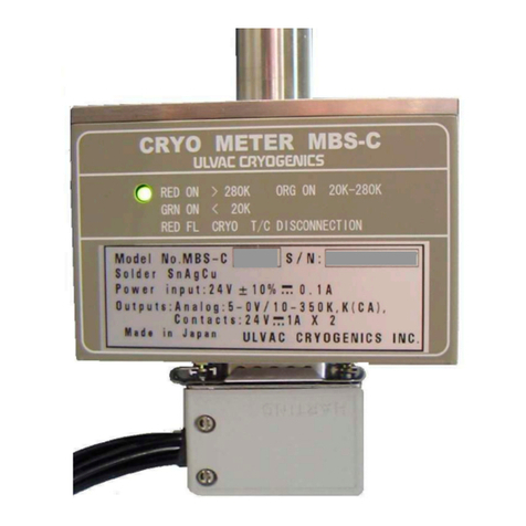
Ulvac MBS-C User manual

Ulvac

Ulvac MBS-C User manual

Ulvac G-Tran Series User manual

Ulvac

Ulvac G-Tran Series User manual

Ulvac G-Tran Series User manual

Ulvac

Ulvac G-Tran Series User manual

Ulvac HELIOT 301 User manual

Ulvac

Ulvac HELIOT 301 User manual

Ulvac GP-2001G User manual

Ulvac

Ulvac GP-2001G User manual

Ulvac GI-M2 Installation guide

Ulvac

Ulvac GI-M2 Installation guide

Ulvac MBD-D User manual

Ulvac

Ulvac MBD-D User manual

Ulvac SPU User manual

Ulvac

Ulvac SPU User manual

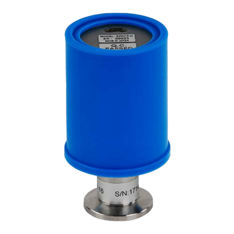
Ulvac SWU10-U User manual

Ulvac

Ulvac SWU10-U User manual

Ulvac G-Tran Series User manual

Ulvac

Ulvac G-Tran Series User manual

Ulvac G-Tran Series User manual

Ulvac

Ulvac G-Tran Series User manual

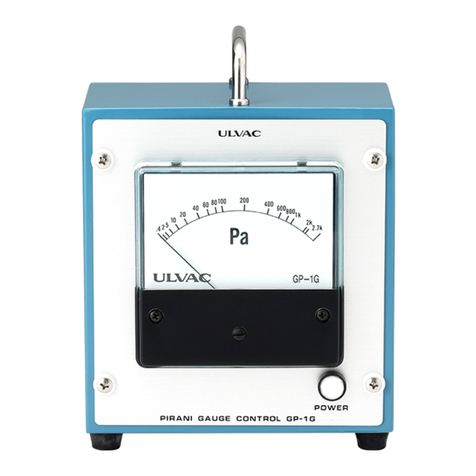
Ulvac GP-1G User manual

Ulvac

Ulvac GP-1G User manual

Ulvac MBD Series User manual

Ulvac

Ulvac MBD Series User manual

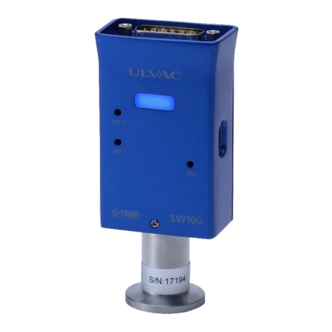
Ulvac G-TRAN SW100-A User manual

Ulvac

Ulvac G-TRAN SW100-A User manual

Popular Measuring Instrument manuals by other brands

Triax MCT 049B user manual

Triax

Triax MCT 049B user manual

Novanta gem with smd24 user manual

Novanta

Novanta gem with smd24 user manual

Greenheck Sure-Aire 386719 Installation, operation and maintenance manual

Greenheck

Greenheck Sure-Aire 386719 Installation, operation and maintenance manual

National Instruments NI 5731 user guide

National Instruments

National Instruments NI 5731 user guide

Saab TankRadar PRO user guide

Saab

Saab TankRadar PRO user guide

Bince LS533H instruction manual

Bince

Bince LS533H instruction manual

HEIDENHAIN TT 460 Mounting instructions

HEIDENHAIN

HEIDENHAIN TT 460 Mounting instructions

Frederiksen 200260 quick start guide

Frederiksen

Frederiksen 200260 quick start guide

Endress+Hauser Proline Prowirl O 200 Brief operating instructions

Endress+Hauser

Endress+Hauser Proline Prowirl O 200 Brief operating instructions

Lutron Electronics AM-4215SD manual

Lutron Electronics

Lutron Electronics AM-4215SD manual

vinmetrica SC-100A user manual

vinmetrica

vinmetrica SC-100A user manual

Rohde & Schwarz R&S NRPM user manual

Rohde & Schwarz

Rohde & Schwarz R&S NRPM user manual

Veris Industries FSR Series installation guide

Veris Industries

Veris Industries FSR Series installation guide

Keithley 220 instruction manual

Keithley

Keithley 220 instruction manual

Omron K3NX Operation manual

Omron

Omron K3NX Operation manual

Trotec SL3000 manual

Trotec

Trotec SL3000 manual

Fluke MultiFiber Pro Product information

Fluke

Fluke MultiFiber Pro Product information

Bridge Technologies VB440 user manual

Bridge Technologies

Bridge Technologies VB440 user manual

manuals.online logo
manuals.online logoBrands
  • About & Mission
  • Contact us
  • Privacy Policy
  • Terms and Conditions

Copyright 2025 Manuals.Online. All Rights Reserved.