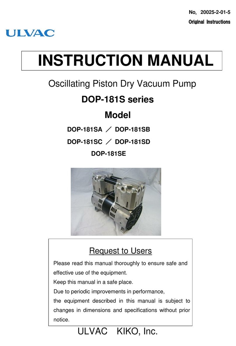
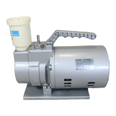
Ulvac MD 4UC NT User manual

page 1 of 28
Documents are only to be used and distributed completely and unchanged. It is strictly the users´ responsibility to check carefully
the validity of this document with respect to his product.
No. 47900-2-02-5
Chemistry diaphragm pump
Instructions for use
MD 4UC NT
The voltage changeover switch at the time of the delivery is "240".
(The voltage corresponds to 180-253V.)
Application at "90-126V":
Please exchange a voltage changeover switch with "120".
Change the selection at the voltage changeover switch only if the pump is separated from
mains.

page 2 of 28
Documents are only to be used and distributed completely and unchanged. It is strictly the users´ responsibility to check carefully
the validity of this document with respect to his product.
No. 47900-2-02-5

page 3 of 28
Documents are only to be used and distributed completely and unchanged. It is strictly the users´ responsibility to check carefully
the validity of this document with respect to his product.
No. 47900-2-02-5
➨Danger! Immediate danger. Death or severe injuries as well as damage
to equipment and environment can occur.
☞Warning! Possible danger. Severe injuries as well as damage to equip-
ment and environment can occur.
• Caution!Possibledanger.Slightinjuriesaswellasdamagetoequip-
ment and environment can occur.
Note. Disregarding of notes may cause damage to the product.
Caution! Hot surface!
Isolate equipment from mains before removing the cover.
NOTICE
Contents
Safety information!.....................................................................................................4
General information............................................................................................................................4
Intended use.......................................................................................................................................4
Setting up and installing the equipment .............................................................................................4
Ambient conditions .............................................................................................................................5
Operating conditions ..........................................................................................................................6
Safety during operation ......................................................................................................................6
Maintenance and repair......................................................................................................................8
Technical data.............................................................................................................9
Gas inlet temperatures ....................................................................................................................10
Wetted parts ....................................................................................................................................10
Pump parts ......................................................................................................................................10
Use and operation ....................................................................................................12
Installing in a vacuum system ..........................................................................................................12
During operation...............................................................................................................................13
Attention: Important notes regarding the use of gas ballast.............................................................13
Shutdown .........................................................................................................................................14
Troubleshooting .......................................................................................................15
Replacing diaphragms and valves..........................................................................16
Cleaning and inspecting the pump heads .......................................................................................17
Replacing the diaphragm ................................................................................................................18
Replacing the valves .......................................................................................................................20
Replacing the device fuse ...............................................................................................................23
Notes on return to the factory.................................................................................24
Check sheet for repair..............................................................................................25

page 4 of 28
Documents are only to be used and distributed completely and unchanged. It is strictly the users´ responsibility to check carefully
the validity of this document with respect to his product.
No. 47900-2-02-5
Safety information!
General information
☞Read and comply with this manual before installing or operating the equip-
ment.
☞Transport the pump at the provided handle.
Remove all packing material, remove the product from its packing-box, remove the
protective covers from the inlet and outlet ports and keep, inspect the equipment.
If the equipment is damaged, notify the supplier and the carrier in writing within three
days; state the item number of the product together with the order number and the
supplier’s invoice number. Retain all packing material for inspection.
Do not use the equipment if it is damaged.
If the equipment is not used immediately, replace the protective covers. Store the
equipment in suitable conditions.
Intended use
☞The pump and all system parts must not be used on humans or animals.
☞Prevent any part of the human body from coming into contact with vacuum.
☞Ensure that the individual components are only connected, combined and oper-
ated according to their design and as indicated in the instructions for use.
☞Comply with notes on correct vacuum and electrical connections, see section
”Use and operation”.
• Thepumpsaredesignedforambient temperatures during operation between
+10°C and +40°C. Check the maximum temperatures if installing the pump in a
cabinet or a housing and make sure ventilation is adequate. Install an external
automatic ventilation system if necessary. If pumping hot process gases make
sure that the maximum permitted gas inlet temperature, which depends on sev-
eral parameters like inlet pressure or ambient temperature (see ”Technical data”),
is not exceeded.
• Particles and dust must not be aspirated.
Use the equipment for the intended use only, i.e. for generation of vacuum in ves-
sels designed for that purpose.
Setting up and installing the equipment
➨Equipment must be connected only to a suitable electrical supply and a suit-
able earth point. Failure to connect the motor to ground may result in deadly
electrical shock.
ThesupplycablemaybettedwithamouldedEuropeanIECplugoraplugsuit-
able for your local electrical supply. If the plug has been removed or has to be
removed, the cable will contain wires colour coded as follows: green or green and
yellow: earth; blue or white: neutral; brown or black: live.
☞Due to the high compression ratio of the pumps, pressure at the outlet port might
be generated being higher than the maximum permissible pressure compatible
with the mechanical stability of the system.
☞Do not permit any uncontrolled pressurizing (e. g. make sure that the exhaust
pipeline cannot become blocked). If there is an exhaust isolation valve, make sure
that you cannot operate the equipment with the valve closed. Risk of bursting!
☞Always provide a free and pressureless exhaust pipeline.
NOTICE
NOTICE
page 5 of 28
Documents are only to be used and distributed completely and unchanged. It is strictly the users´ responsibility to check carefully
the validity of this document with respect to his product.
No. 47900-2-02-5
• Complywithmaximum permissible pressures at inlet and outlet and pressure
differences, see section ”Technical data”. Do not operate the pump with overpres-
sure at the inlet.
• Check that mains voltage and current conform with the equipment (see rating
plate).
• Change the setting of the voltage changeover switch (pump with dual-voltage
motor) only if the pump is separated from mains. Check that the voltage changeo-
ver switch is set correctly. Attention: If the pump is switched on with wrong volt-
age selection, the motor might be damaged!
• Avoidoverpressureofmorethan0.2barincaseinertgasis connectedtothe
pump, the gas ballast or to a venting valve.
• Connectpipesgastightatinletandoutletofthepump.
• Attention: Flexible elements tend to shrink when evacuated.
Provide a rm level platform for the equipment and check that the system to be
evacuatedismechanicallystableandthatallttingsaresecure.Ensureastablepo-
sition of the pump without any mechanical contact except of the pump feet. Comply
with all applicable safety regulations.
Keep a distance of minimum 20 cm between fan and ambient parts (e.g. housing,
walls, ...). Check fan regularly for dust/dirt, clean if necessary to avoid a cutback of
ventilation.
If the equipment is brought from cold environment into a room for operation, allow
the equipment to warm up (pay attention to water condensation on cold surfaces).
The diameter of the inlet and outlet pipeline should be at least as large as the diam-
eter of the pump connection pipelines.
Comply with all applicable and relevant safety requirements (regulations and
guidelines), implement the required actions and adopt suitable safety meas-
ures.
Ambient conditions
To the best of our knowledge the equipment is in compliance with the requirements
of the applicable EC-directives and harmonized standards (see ”Declaration of con-
formity”) with regard to design, type and model. Directive IEC 1010 gives in detail
conditions under which the equipment can be operated safely (see also IP degree
of protection).
Adopt suitable measures in case of differences, e. g. using the equipment outdoors,
installation in altitudes of more than 1000 m above mean sea level, conductive pol-
lution or bedewing.
Pay attention to the permissible maximum ambient and gas inlet temperatures
(see ”Technical data”).
NOTICE
NOTICE

page 6 of 28
Documents are only to be used and distributed completely and unchanged. It is strictly the users´ responsibility to check carefully
the validity of this document with respect to his product.
No. 47900-2-02-5
Operating conditions
➨The pumps have no approval for operation in or for pumping of potentially
explosive atmospheres.
➨The pumps are not suitable to pump
- unstable substances and substances which react explosively under
impact (mechanical stress) and/or when being exposed to elevated
temperatures without air,
-self inammable substances,
-substances which are inammable without air and
- explosive substances.
• The pumps are not suitable for pumping substances which may form deposits
inside the pump. Deposits and condensate in the pump may lead to increased
temperatures even to the point of excessing the maximum permitted tempera-
tures!
• Ifthereisadangerofformationofdeposits in the pump chamber (check inlet
and outlet of the pump), inspect the pump chambers regularly and clean if neces-
sary.
• Thepumpsarenot suitable for pumping dust and have no approval for opera-
tion below ground.
If pumping different substances, it is recommended to purge the pump with air or
inert gas prior to changing the pumped media in order to pump out residues and to
avoid reactions of the pumped substances with each other and with the pump ma-
terials.
Take into consideration interactions and chemical reactions of the pumped
media. Ensure that the materials of the wetted parts are compatible with the pumped
substances, see section ”Technical data”.
Safety during operation
➨Adopt suitable measures to prevent the release of dangerous, toxic, explosive,
corrosive,noxiousorpollutinguids,vapoursandgases.Incaseinstallanap-
propriate collecting and disposal system and take protective action for pump and
environment.
➨Prevent any part of the human body from coming into contact with vacuum.
➨The user must take suitable precautions to prevent any formation of explosive
mixtures in the expansion chamber or at the outlet. In case of e.g. a diaphragm
crack, mechanically generated sparks, hot surfaces or static electricity may ignite
these mixtures. Use inert gas for gas ballast or venting if necessary.
➨Potentially explosive mixtures at the outlet of the pump have to be drained ap-
propriately, sucked off or diluted with inert gas to non-explosive mixtures.
☞Pay attention to the symbol ”hot surfaces” on the equipment. Adopt suitable
measures to prevent any danger arising from the formation of hot surfaces or
electric sparks. Provide a suitable protection against contact if necessary.
☞Pumping at high inlet pressure may lead to overpressure at the gas ballast
valve. Pumped gases or condensate might be pushed out in case the valve is
open. If an inert gas supply is connected, ensure that the inlet pipeline is not con-
taminated.
NOTICE

page 7 of 28
Documents are only to be used and distributed completely and unchanged. It is strictly the users´ responsibility to check carefully
the validity of this document with respect to his product.
No. 47900-2-02-5
• Complywithapplicableregulationswhendisposingofchemicals.Takeintocon-
sideration that chemicals may be polluted.
Take adequate precautions to protect people from the effects of dangerous sub-
stances(chemicals,thermaldecompositionproductsofuoroelastomers),wear
appropriate safety-clothing and safety glasses.
• Use only OEM spare parts and accessories. Otherwise safety and perform-
ance of the equipment as well as the electromagnetic compatibility of the equip-
ment might be reduced.
Possibly the CE mark or the cTÜVus mark become void if not using OEM spare
parts.
• Failure of the pump (e.g. due to power failure) or of connected components,
parts of the supply or change of parameters must not lead to a critical dangerous
situation under any circumstances. In case of diaphragm cracks or leaks in the
manifold pumped substances might be released into the environment or into the
pump housing or motor. Comply especially with notes on operation and use and
maintenance.
• Duetotheresidualleak rate of the equipment, there might be an exchange of
gas, albeit extremely slight, between the environment and the vacuum system.
Adopt suitable measures to prevent contamination of the pumped substances or
the environment.
Do not start the pump if the pressure difference between inlet and outlet port ex-
ceeds 1.1 bar at maximum.
Preventthebackpressureofgasesandthebackowofcondensates.
Never suck liquids or dust into the pump.
Provide appropriate protective measures (i.e. precautions which allow for the re-
quirements of the respective application) even for the case of failure and malfunc-
tion.
In case of overload the motor is shut down by a self-hold thermal cutout in the
winding.
Attention: Reset possible only manually. Switch off the pump or isolate the equip-
mentfrommains.Identifyandeliminatethecauseoffailure.Waitapprox.vemin-
utes before restarting the pump.
Attention: In case of supply voltage below 100V, the lock of the cutout might be
restrictedandthepumpmightrestartonitsownaftersufcientcoolingdown.Take
suitable precautions, if an automatic restart of the pump may lead to a critical dan-
gerous situation.
The A-weighted emission sound pressure level of the pump does not exceed 70
dB(A). Measurement according to EN ISO 2151:2004 and EN ISO 3744:1995 with
standard silencer or exhaust tube at outlet.
NOTICE

page 8 of 28
Documents are only to be used and distributed completely and unchanged. It is strictly the users´ responsibility to check carefully
the validity of this document with respect to his product.
No. 47900-2-02-5
☞Ensure that the pump cannot be operated accidentally. Never operate the
pump if covers or other parts of the pump are disassembled. Never operate
a defective or damaged pump.
☞Attention: The pump might be contaminated with process chemicals which have
been pumped during operation. Ensure that the pump is decontaminated before
maintenance and take adequate precautions to protect people from the effects of
dangerous substances if contamination has occurred.
• Beforestartingmaintenanceventthepump,isolatethepumpandothercompo-
nentsfromthevacuumsystem.Allowsufcientcoolingofthepump.
Ensure that maintenance is done only by suitably trained and supervised techni-
cians. Ensure that the maintenance technician is familiar with the safety procedures
which relate to the products processed by the pumping system.
In order to comply with law (occupational, health and safety regulations, safety at
work law and regulations for environmental protection) vacuum pumps, components
and measuring instruments returned to the manufacturer can be repaired only when
certain procedures (see section ”Notes on return to the factory”) are followed.
Maintenance and repair
Wear parts have to be replaced regularly. In case of normal wear the lifetime of the
diaphragms and valves is > 10000 operating hours. Bearings have a typical durability
of 40000 h. Motor capacitors have a typical durability in the range of 10000 to 40000 h de-
pending strongly on the operation conditions like ambient temperature, humidity or load.
• Checkeverycapacitorregularlybymeasuringitscapacityandestimatingitsop-
eration time. Exchange old capacitors early enough to prevent a failure. If an
overaged motor capacitor fails it might get hot and even melt and may cause a
ametoformwhich couldbedangerous for persons and equipment in the
vicinity. The capacitors have to be replaced by an electrician.
➨Isolate equipment from mains and wait two minutes before starting mainte-
nance to allow the capacitors to discharge.

page 9 of 28
Documents are only to be used and distributed completely and unchanged. It is strictly the users´ responsibility to check carefully
the validity of this document with respect to his product.
No. 47900-2-02-5
Type MD 4UC NT
Maximum pumping speed*
50/60 Hz (ISO 21360) m3/h 3.4 / 3.8
Ultimate vacuum (absolute) without gas ballast mbar 1.5
Ultimate vacuum (absolute) with gas ballast mbar 3
Maximum permissible inlet pressure (absolute) bar 1.1
Maximum permissible outlet pressure (absolute) bar 1.1
Maximum permissible pressure (absolute) at
gas ballast valve bar 1.2
Permissible ambient temperature
storage / operation °C -10 to +60 / +10 to +40
Permissible relative atmospheric moisture during
operation
(no condensation)
%30 to 85
Rated motor power kW 0.25
No-load speed 50/60 Hz min-1 1500 / 1800
Maximum permissible range of supply voltage
( ±10% )
Attention: Observe specications on rating plate!
100-115 V~ 50/60 Hz,
120 V~ 60 Hz /
200-230 V~ 50/60 Hz
Maximum rated current at:
100-115 V~ 50/60 Hz 120 V~ 60 Hz
200-230 V~50/60 Hz
A
A
5.7
3.0
Device fuse slow blow fuse 6.3 A
Motor protection thermal cutout, manual reset
Degree of protection IEC 529 IP 40
Inlet hose nozzle DN 10 mm
Outlet hose nozzle DN 10 mm
Dimensions L x W x H approx. mm 325 x 243 x 198
Weight approx. kg 14.3
We reserve the right for technical modications without prior notice!
Technical data

page 10 of 28
Documents are only to be used and distributed completely and unchanged. It is strictly the users´ responsibility to check carefully
the validity of this document with respect to his product.
No. 47900-2-02-5
Pump parts
Wetted parts
We reserve the right for technical modication without prior notice!
Gas inlet temperatures
Operating condition Inlet pressure Permitted range of gas
temperatures at inlet
Continuous operation > 100 mbar (high gas load) +10°C to +40°C
Continuous operation < 100 mbar (low gas load) 0°C to +60°C
Short-time (< 5 minutes) < 100 mbar (low gas load) -10°C to +80°C
Components Wetted materials
Head cover ETFEcarbonbrereinforced
Diaphragm clamping disc ETFEcarbonbrereinforced
Diaphragm PTFE
Valves FFKM
O-rings FPM
Valve head ECTFEcarbonbrereinforced
Gas ballast tube PTFE carbon reinforced
Inlet PTFE
Outlet PTFE
Tubing PTFE
Position Component
1 Inlet
2 Outlet
3 Gas ballast valve
4 ON/OFF switch
5 Mains connection
6 Handle
7 Pump rating plate
8 Fan
9 Voltage changeover switch

page 11 of 28
Documents are only to be used and distributed completely and unchanged. It is strictly the users´ responsibility to check carefully
the validity of this document with respect to his product.
No. 47900-2-02-5
MD 4UC NT
1
5
3
4
7
6
2
8
9

page 12 of 28
Documents are only to be used and distributed completely and unchanged. It is strictly the users´ responsibility to check carefully
the validity of this document with respect to his product.
No. 47900-2-02-5
Use and operation
Installing in a vacuum system
• Connectionlinesatthepumpinlethavetobegastight.Particlesanddustmust
notbeaspirated,theuserhastoprovideappropriateltersifnecessary.Theuser
mustensuretheirsuitabilityconcerninggasow,chemicalresistanceandsafe-
ness against clogging prior to use.
• Connectanexhaustlinegastightatthepumpoutletifnecessary.Alwaysdispose
of exhaust gases appropriately (e.g. into a fume hood). If there is risk of release of
dangerousorpollutinguids,installanappropriatesystemtocatchanddispose
ofthoseuids.
• Reduce the transmission of vibration and prevent mechanical load due to rig-
idpipelines.Insertelastichosesorexibleelementsascouplingsbetweenthe
pump and rigid pipes. Attention: Flexible elements tend to shrink when evacu-
ated.
• Thegasoutletmustneverbeblocked.Theexhaustlinehasalwaystobefree
(pressureless) to ensure an unimpeded discharge of gas.
• Especiallyifthegasballastvalveisopen,apowerfailuremaycauseaccidental
ventilation of the pump. In case this constitutes a potential source of danger, take
appropriate safety measures.
• Pump with dual-voltage motor: Check that the voltage changeover switch at
the terminal box is positioned correctly.
Attention: If the pump is switched on with wrong voltage selection, the motor
may be damaged!
Before starting the pump, check that the voltage changeover switch at the termi-
nal box is correctly positioned.
Change the selection at the voltage changeover switch only if the pump is
separated from mains.
• Makesureventilationisadequateespeciallyifthepumpisinstalledinahousing
or if the ambient temperature is elevated. Provide external ventilation if neces-
sary. Keep a distance of minimum 20 cm between fan and ambient parts.
Avoid throttling losses by using connecting pipes with large diameter and by keeping
them as short as possible.
In case of perturbing exhaust noise connect an exhaust hose or use a silencer.Install
outletpipelinesalwaysfallingtoavoidbackowofcondensatetowardsthepump.
Use of a suitable valve to isolate the pump from the vacuum system is recommended
to allow the pump to warm up before pumping condensable vapours or to clean the
pump before it is switched off.
When assembling, ensure vacuum-tightness. After assembly, check the whole sys-
tem for leaks.
Secure hose connections at the pump appropriately against accidental detaching.
NOTICE
Voltage selection switch:
1. Disconnect the electrical power cord.
2. Use a screw driver to adjust the voltage selection switch at the terminal
box of the pump to the supply voltage:
”120” corresponds to 90-126 V and ”240” corresponds to 180-253 V.
voltage selection
switch

page 13 of 28
Documents are only to be used and distributed completely and unchanged. It is strictly the users´ responsibility to check carefully
the validity of this document with respect to his product.
No. 47900-2-02-5
• Thegasoutlet(hosenozzle10mm)mustnotbeblocked.Theexhaustpipeline
has always to be free and pressureless to enable an unhindered discharge of
gases.
• Ifnecessaryconnecttheexhausttoasuitabletreatmentplanttopreventthedis-
charge of dangerous gases and vapours to the surrounding atmosphere.
Attention: Important notes regarding the use of gas ballast
➨Whenusingairratherthaninertgas,riskofsignicantdamagetoequipmentand/
or facilities, risk of personal injury or even loss of life exists due to the formation
of hazardous and/or explosive mixtures if air and pumped media react inside or
at the outlet of the pump.
☞Make sure that air/gas inlet through the gas ballast valve never leads to hazard-
ous, explosive or otherwise dangerous mixtures. If in doubt, use inert gas.
During operation
•Maximum ambient temperature: 40 °C
• Makesureventilationisadequateespeciallyifthepumpisinstalledinahousing
or if the ambient temperature is elevated.
• Potentially dangerous gases or vapours at the outlet of the pump have to be
drained and disposed of appropriately.
• Duetothehighcompressionratioofthepumps,thepressureattheoutletportmight
get higher than the maximally permitted pressure compatible with the mechanical
stability of the system. Ensure that the pump outlet is not blocked or restricted.
If pumping condensable vapours (water vapour, solvents, ....), let the pump run with
gas ballast to reduce condensation in the pump.
If the pump is installed in altitudes of more than 1000 m above mean sea level check
compatibility with applicable safety requirements, especially IEC 60034 (motor might
overheatduetoinsufcientcooling).
Do not start the pump if the pressure at outlet port exceeds maximum 1.1 bar
(absolute). Attempts to start the pump at higher pressures may cause blockade and
damage of the motor.
Check compatibility with maximally permitted pressure at inlet and outlet.
Prevent internal condensation, transfer of liquids or dust. The diaphragms and valves
willbedamaged,ifliquidsarepumpedinsignicantamounts.
Check the pump regularly for external soiling and deposits, clean if necessary to
avoid an increase of the pump‘s operating temperature.
In case of excess temperature, the motor is shut down by a thermal cutout in the
winding. Attention: Reset possible only manually. Switch off the pump or isolate the
equipment from mains. Determine and eliminate the cause of failure. Wait approx.
veminutesbeforerestartingthepump.
Attention: In case of supply voltage below 100V, the lock of the cutout might be
restrictedandthepumpmightrestartonitsownaftersufcientcoolingdown.Take
suitable precautions, if an automatic restart of the pump might lead to a dangerous
situation.
A warm up period (approx. 15 min.) is required to ensure that the rated ultimate
vacuum and pumping speed are attained. Avoid high heat supply (e. g. due to hot
process gases).
NOTICE

page 14 of 28
Documents are only to be used and distributed completely and unchanged. It is strictly the users´ responsibility to check carefully
the validity of this document with respect to his product.
No. 47900-2-02-5
In case of low boiling solvents (when the formation of condensate is unlikely), the
use of gas ballast might be unnecessary.
For condensable vapours (water vapour, solvents, ...):
☞Do not pump vapour before pump has reached its operat-
ing temperature. Open gas ballast valve when pumping
condensable vapours.
☞The gas ballast valve is open, if the arrow on the gas bal-
last cap is pointing towards the labelling ”GB”.
☞With gas ballast valve open, the ultimate vacuum will be
reduced.
☞Use inert gas for gas ballast to avoid the formation of ex-
plosive mixtures.
☞Close the gas ballast valve by turning the cap 180°.
gas
ballast
(open)
Shutdown
Short-term:
Has the pump been exposed to condensate?
Allow the pump to continue to run at atmospheric pressure for a few minutes.
Has the pump been exposed to media which may damage the pump materials or
form deposits?
Check and clean pump heads if necessary.
Long-term:
Take measures as described in section short-term shutdown.
Separate pump from the apparatus.
Close inlet and outlet port (e. g. with transport caps).
Close the gas ballast valve.
Store the pump in dry conditions.
NOTICE

page 15 of 28
Documents are only to be used and distributed completely and unchanged. It is strictly the users´ responsibility to check carefully
the validity of this document with respect to his product.
No. 47900-2-02-5
Troubleshooting
Fault Possible cause Remedy
❑ Pump does not start or
stops immediately.
➨Mains not plugged in, electri-
cal supply failure?
✔Plug in mains. Check fuse.
➨Device fuse blown? ✔Identify cause of failure. Re-
place device fuse.
➨Pressure in outlet pipeline too
high?
✔Remove blockade in line,
open valve.
➨Motor overloaded? ✔Allow motor to cool down,
identify and eliminate cause
of failure. Manual reset is
necessary. Switch off pump
or unplug mains.
❑Pump does not achieve
its ultimate vacuum or
usual pumping speed.
➨Centringringatsmallange
connection not correctly posi-
tioned or leak in the pipeline
or vacuum system?
✔Check pump directly - con-
nect vacuum gauge directly
at pump inlet - then check
connection, pipeline and
vacuum system if necessary.
➨Long, narrow line? ✔Use lines with larger di-
ameter, length as short as
possible.
➨Pump has been exposed to
condensate?
✔Allow pump to run for some
minutes with atmospheric
pressure at the inlet.
➨Deposits have been formed
inside the pump?
✔Clean and inspect the pump
heads.
➨Diaphragms or valves dam-
aged?
✔Replace diaphragms and/or
valves.
➨Outgassing substances or
vapour generated in the proc-
ess?
✔Check process parameters.
❑Pump too noisy. ➨Loud exhaust noise? ✔Connect hose or silencer to
pump outlet.
➨Diaphragm crack or dia-
phragm clamping disc loose?
✔Perform maintenance.
➨Other than above mentioned
causes?
✔Contact local distributor.
❑Pump seized. ✔Contact local distributor.

page 16 of 28
Documents are only to be used and distributed completely and unchanged. It is strictly the users´ responsibility to check carefully
the validity of this document with respect to his product.
No. 47900-2-02-5
☞Please read section ”Replacing diaphragms and valves” completely before
starting maintenance.
Partiallythepicturesshowpumpsinotherversions.Thisdoesn’tinuencereplacingdiaphragmsand
valves of the pump.
Tools required (metric):
- Torx screw driver TX20
- Hex key size 5
- Flat-bladed screw driver 2.5 mm
- Flat pliers
- Diaphragm key w/f 66
Replacing diaphragms and valves
Allbearingsareencapsulatedandarelledwithlong-lifelubricant.Undernormaloper-
ating conditions, the pump is maintenance free. The valves and diaphragms as well as
the motor capacitors are wear parts. If the rated ultimate vacuum is no longer achieved
or in case of increased noise level, the pump interior, the diaphragms and the valves
must be cleaned and the diaphragms and valves must be checked for cracks or other
damage. Check every capacitor regularly by measuring its capacity and estimating its
operation time. Exchange old capacitors early enough to prevent a failure. The capaci-
tors have to be replaced by an electrician. Depending on individual cases it may be
efcienttocheckandcleanthepumpheadsonaregularbasis.Incaseofnormalwear
the lifetime of the diaphragms and valves is > 10000 operating hours.
- Prevent internal condensation, transfer of liquids or dust. The diaphragm and
valveswillbedamaged,ifliquidsarepumpedinsignicantamount.
If the pump is exposed to corrosive media or in case of deposits, maintenance should
be carried out frequently.
- Regular maintenance will improve the lifetime of the pump and also protect both
man and environment.
Ensure that maintenance is done only by suitable trained and supervised technicians.
☞Ensure that the pump cannot be operated accidentally. Never operate the pump
if covers or other parts of the pump are disassembled. Never operate a de-
fective or damaged pump.
☞Before starting maintenance isolate the pump from the electrical supply and
wait two minutes after isolating the equipment from mains to allow the capaci-
torstodischarge.Avoidthereleaseofpollutants.Allowsufcientcoolingofthe
pump before starting maintenance.
• Attention:Thepumpmightbecontaminatedwiththeprocesschemicalsthathave
been pumped during operation. Ensure that the pump is decontaminated before
maintenance and take adequate precautions to protect people from the effects
of dangerous substances if contamination has occurred. Ensure that the mainte-
nance technician is familiar with the safety procedures which relate to the prod-
ucts processed by the pumping system.
• Wearappropriatesafety-clothingwhenyoucomeintocontactwithcontaminated
components. Avoid the release of pollutants.
Before starting maintenance vent the pump and isolate it from the vacuum sys-
tem.
NOTICE
Set of seals (diaphragms, valves, O-rings) ..............................................................................20696870
Diaphragm key (w/f 66) ...........................................................................................................20636397

page 17 of 28
Documents are only to be used and distributed completely and unchanged. It is strictly the users´ responsibility to check carefully
the validity of this document with respect to his product.
No. 47900-2-02-5
1: Cylinder pin / mark
2: Connecting rod
3: Housing
4: Washer
5: Diaphragm support disc
6: Diaphragm
7: Diaphragm clamping disc with square
head screw
8: Socket head screw
9: Blind
10: Head cover
11:Square nut
12:Fillister head screw
13:O-ring
14: Valve
15:Valve head
16: Hose nozzle
17:Connection fastener with hinged cover
18:Disc spring
19:Clamping bracket
20:Countersunk screw
21:Hose clip
22:Connection tube
Cleaning and inspecting the pump heads
The replacement of the diaphragm and the replacement of the valves can be carried out separately.
☞ To replace the valves, remove the head covers of one side of the pump conjointly with the assembled
valveheadsandttings.
☞ Tomaintainthediaphragms,thevalveheadsandthettingsdon’thavetobedisassembled.The
headcoverscanberemovedconjointlywiththeassembledvalveheadsandttings.
☞ Maintain only one side of the pump at a time.
View of the disassembled pump head parts
10
1
9
3
2
5
6
7
8
11
18
20
13
12
14
19
16
21
17
22 15
4

page 18 of 28
Documents are only to be used and distributed completely and unchanged. It is strictly the users´ responsibility to check carefully
the validity of this document with respect to his product.
No. 47900-2-02-5
➨ UseaTorxscrewdriverTX20tounscrewthe4screwsx-
ating the head cover cowling. Pay attention to the washers
under the screws and remove.
➨Pull off head cover cowling carefully. Do not cant.
Opening the hose clip:
➨Apply screw driver as shown and turn.
Detachthexingoftheconnectiontubetotheothersideof
the pump at the valve head.
➨ Openthehoseclipwithaat-bladedscrewdriver.
➨Pull the tubing off the hose connector.
Replacing the diaphragm
➨Disassemble head covers to check the diaphragm.
➨Unscrew four (pump with two cylinders) or eight (pump
with four cylinders) socket head screws with a hex key size
5 and remove both head covers (pumps with two cylin-
ders: only one head cover) together with valve heads and
connections.
☞It is not necessary to disassemble the valve heads, the
connection fasteners, or the hose connection between the
adjacent head covers (pumps with four cylinders).
Fittings and tubing
MD 4UC NT

page 19 of 28
Documents are only to be used and distributed completely and unchanged. It is strictly the users´ responsibility to check carefully
the validity of this document with respect to his product.
No. 47900-2-02-5
➨Position new diaphragm between diaphragm clamping
disc with square head screw and diaphragm support disc.
☞Attention: Position diaphragm with pale side towards dia-
phragm clamping disc (to pump chamber).
☞Make sure that the square head screw of the diaphragm
clamping disc is correctly seated in the guide hole of the
diaphragm support disc.
➨Lift diaphragm at the side and position carefully together
with diaphragm clamping disc and diaphragm support disc
in the diaphragm key.
☞Avoid damage of the diaphragm: Do not bend diaphragm
too much.
➨Check for washers between the diaphragm support disc
and the connecting rod. Do not mix the washers from the
different pump heads. Make sure that the original number
is reassembled at the individual pump head.
☞ Iftheolddiaphragmisdifculttoseparatefromthesupport
disc, immerse assembly in naphtha or petroleum ether. Do
not inhale!
☞Too small number of washers: The pump will not attain
ultimate vacuum. Too many washers: Clamping disc will
hit head cover; noise or even blockade of the pump.
☞Check diaphragm for damage and replace if necessary.
➨Lift diaphragm carefully sidewise.
☞Never use a spiky or sharp-edged tool to lift the dia-
phragm.
➨Use the diaphragm key to grip the diaphragm support disc
below the diaphragm.
➨Unscrew diaphragm support disc with diaphragm and dia-
phragm clamping disc.
☞Assemble the original number of washers between sup-
port disc and connecting rod.
➨Screw diaphragm clamping disc, diaphragm, diaphragm
support disc and washers to connecting rod.
➨Optimum torque for the diaphragm support disc: 6 Nm, it
is recommended to use a torque key. Attach hex key to
diaphragm key (hexagonal bolt 6 mm wide).
Attention: Never use the diaphragm key with any addi-
tional tools like tongs or hex keys without torque limita-
tion.

page 20 of 28
Documents are only to be used and distributed completely and unchanged. It is strictly the users´ responsibility to check carefully
the validity of this document with respect to his product.
No. 47900-2-02-5
Replacing the valves
➨Remove valve heads conjointly with disc springs, con-
nection tube if applicable, hose nozzles and connection
fasteners or move the valve heads carefully aside. Note
position and orientation of the valve heads.
☞Note position of valves.
➨Check valves and O-rings for damages and soiling.
➨Replace valves or O-rings if necessary.
➨Use petroleum ether or industrial solvent to remove de-
posits. Do not inhale.
Loosen the clamping brackets on the valve heads.
➨Unscrew at each clamping bracket the two countersunk
screws with a Torx screw driver TX20. Remove the clamp-
ing brackets.
Loosen connection fastener slightly.
➨ TurnthellisterheadscrewwithaTorxscrewdriverTX20
one turn at most.
☞ Do not detach the llister head screw from the square
nut.
➨Open the hinged cover of the connection fastener with a
at-bladedscrewdriver.
➨ InsertO-ringsandvalves.Seegureforthecorrectposi-
tion of the valves:
☞Inlet side (IN):
Marked ”IN” next to the valve seat. The valve tongue points
atthereniformoriceinthevalveseat.
☞Outlet side (EX):
Marked with ”EX” next to the valve seat. The valve is ori-
ented the same way as the valve at the inlet side.
EX
IN
Table of contents
Other Ulvac Water Pump manuals

Ulvac
Ulvac GCD-051X User manual

Ulvac
Ulvac Desktop YTP User manual

Ulvac
Ulvac G-20DA User manual

Ulvac
Ulvac DOP-301SB User manual

Ulvac
Ulvac DIS-251 User manual

Ulvac
Ulvac GLD-040 User manual

Ulvac
Ulvac G-101D User manual

Ulvac
Ulvac TM-2 User manual

Ulvac
Ulvac GLD-051 User manual

Ulvac
Ulvac ULK-04A User manual

Ulvac
Ulvac UTM2300 Series User manual

Ulvac
Ulvac PBL Series User manual

Ulvac
Ulvac VD30C User manual

Ulvac
Ulvac DOP-400SB User manual

Ulvac
Ulvac CRYO-U12H User manual

Ulvac
Ulvac G-20DA User manual

Ulvac
Ulvac DA-41D User manual

Ulvac
Ulvac DAP-9D-DC24 User manual

Ulvac
Ulvac CR16B User manual

Ulvac
Ulvac VS1501 User manual