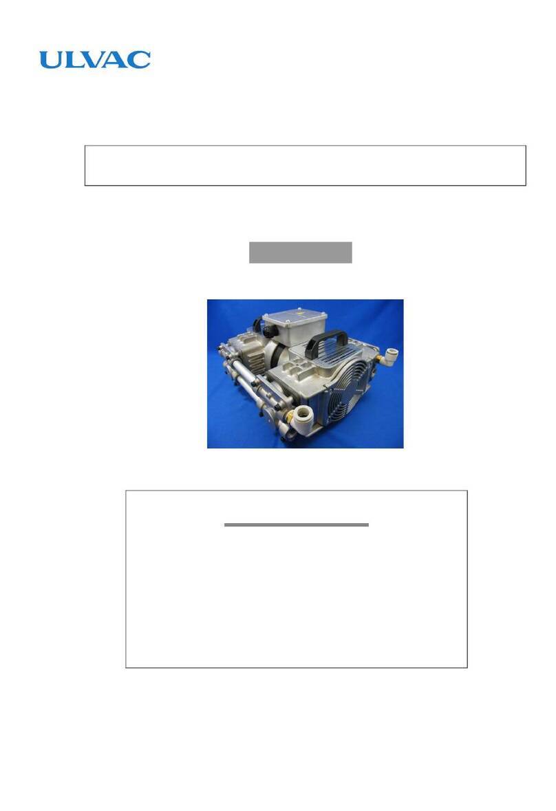
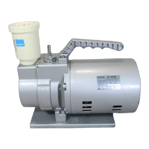
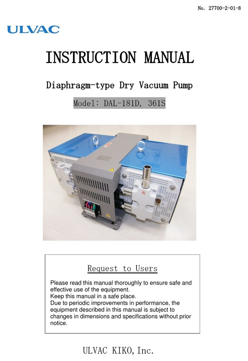
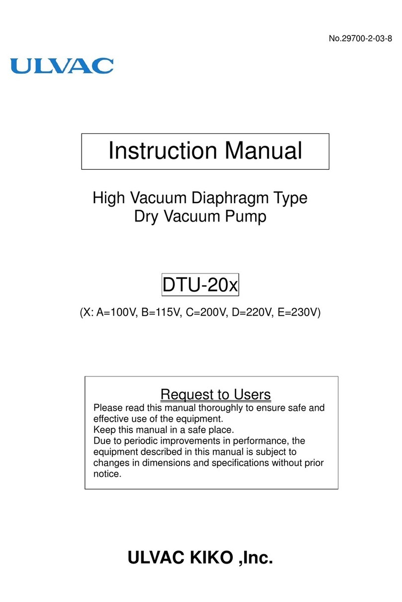
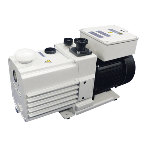
Ulvac DOP-181S Series User manual

No.20025-2-01-5
Original Instructions
INSTRUCTION MANUAL
Oscillating Piston Dry Vacuum Pump
DOP-181S series
Model
DOP-181SA /DOP-181SB
DOP-181SC /DOP-181SD
DOP-181SE
Request to Users
Please read this manual thoroughly to ensure safe and
effective use of the equipment.
Keep this manual in a safe place.
Due to periodic improvements in performance,
the equipment described in this manual is subject to
changes in dimensions and specifications without prior
notice.
ULVAC KIKO, Inc.

We,
Company:ULVAC KIKO,Inc.
of
Address:291-7 Chausubaru Saito-city,Miyazaki (ZIP Cord:881-0037) Japan.
This declaration is issued under the sole responsibility of the manufacturer.
In accordance with the following Directive:
2006/42/EC
Machinery Directive
2011/65/EU+(EU)2015/863
RoHS Directive
declare under our sole responsibility that the product,
Type of Product
:
Oscillating Piston Type Dry Vacuum Pump
Model Name
:
DOP-181SA,DOP-181SB,DOP-181SC
DOP-181SD,DOP-181SE
to which this declaration related is in conformity with the following standards:
EN 1012-2:1996+A1:2009
Compressors and vacuum pumps – Safety requirements, Part2. Vacuum pumps
IEC EN 61010-1:2010+A1:2019
Safety requirement for electrical equipment for measurement, control and laboratory use
Part1.General requirement
following the provisions of
The person stated below will keep the following technical documentation:
operating and maintenance instructions
technical drawings
description of measures designed to ensure conformity
other technical documentation, e.g. quality assurance measures for design and production
Person authorized to compile the technical file:
( Name and address) Chris Goebel
ULVAC GmbH
Klausnerring 4 85551 Kirchheim b. München, Germany
31.Mar, 2023
Makoto Uchimura
Miyazaki , Japan
Development manager
(date & place)
(name, function, signature)
Declaration of Conformity

We,
Company:ULVAC KIKO,Inc.
of
Address:291-7 Chausubaru Saito-city,Miyazaki (ZIP Cord:881-0037) Japan.
This declaration is issued under the sole responsibility of the manufacturer.
In accordance with the following Directive:
Supply of Machinery (Safety) Regulations 2008
(S.I. 2008 No. 1597, as amended by S.I. 2019 No. 696)
The Restriction of the Use of Certain Hazardous Substances in Electrical and
Electronic Equipment Regulations 2012 (S.I. 2012 No. 3032)
declare under our sole responsibility that the product,
Type of Product
:
Oscillating Piston Type Dry Vacuum Pump
Model Name
:
DOP-181SA,DOP-181SB,DOP-181SC
DOP-181SD,DOP-181SE
to which this declaration related is in conformity with the following standards:
BS EN 1012-2:1996+A1:2009
Compressors and vacuum pumps – Safety requirements, Part2. Vacuum pumps
BS IEC EN 61010-1:2010+A1:2019
Safety requirement for electrical equipment for measurement, control and laboratory use
Part1.General requirement
following the provisions of
The person stated below will keep the following technical documentation:
operating and maintenance instructions
technical drawings
description of measures designed to ensure conformity
other technical documentation, e.g. quality assurance measures for design and production
Person authorized to compile the technical file:
( Name and address) Chris Goebel
ULVAC GmbH
Klausnerring 4 85551 Kirchheim b. München, Germany
31.Mar, 2023
Makoto Uchimura
Miyazaki , Japan
Development manager
(date & place)
(name, function, signature)
Declaration of Conformity

Contents
Pages with a shaded background are those which contain items related to safety.
0.Before Using the Equipment.........................................................................................................01
0.1 Checks When Opening Packaging .....................................................................................02
0.2 Using the Pump Safety.......................................................................................................03
・Safety symbols.......................................................................................................................03
・Cautions for Safety in Use......................................................................................................04
1. Product Outline...............................................................................................................................1
1.1 Purpose of Use and Prohibitions ..............................................................................................1
1.2 Specifications ...........................................................................................................................1
1.3 Thermal Protector.....................................................................................................................2
2. Dimensions ....................................................................................................................................2
3. Installation and Storage..................................................................................................................4
3.1 Cautions for Installation and Storage........................................................................................4
3.2 Environmental Conditions for Installation, Storage, and Operation ...........................................4
3.3 Location....................................................................................................................................4
3.4 Operational Checks Following Installation ................................................................................5
3.5 Electric connection ...................................................................................................................5
3.6 Fluctuations in the power voltage and frequency......................................................................6
3.7 The rubber leg installation method of accessories ..................................................................6
3.8 Piping.......................................................................................................................................7
3.9 Storage.....................................................................................................................................7
4. Cautions for Operation ...................................................................................................................8
4.1 Cautions for Operation..............................................................................................................8
4.2 Operation of the Thermal Protection Relay...............................................................................8
4.3 Starting in Cold Weather...........................................................................................................8
5. Pump Performance.........................................................................................................................8
5.1 Ultimate Pressure.....................................................................................................................8
5.2 Pumping Speed........................................................................................................................9
5.3 Power Requirements................................................................................................................9
6. Maintenance, Inspection, and Repair .............................................................................................9
6.1.Cautions for Maintenance, Inspection, and Repair....................................................................9
6.2 Maintenance...........................................................................................................................10
6.3 Regular Inspections................................................................................................................10
6.4 Replacing Consumables and Cleaning...................................................................................11
6.5 Troubleshooting List ...............................................................................................................16
7. In Conclusion................................................................................................................................17
・Warranty.................................................................................................................................17
・Usage Status Check Sheet
・Product information, service bases, and contact information
Figures and Tables
Fig. 2.1 DOP―181SA/181SB ......................................................................................................2
Fig. 2.2 DOP―181SC/181SD......................................................................................................3
Fig. 2.3 DOP―181SE ....................................................................................................................3
Fig. 3.1 Change region of the voltage and frequency......................................................................6
Fig. 3.2 Example of Piping Used When Evacuating a Vessel .........................................................7
Fig. 6.1 Exploded view .................................................................................................................15
Table 1.1 Product Specifications ......................................................................................................1
Table 4.1 Characteristics of the thermal protector .............................................................................8
Table 6.1 Consumables List............................................................................................................10
Table 6.2 Locations for Maintenance and Inspection....................................................................... 11
Table 6.3 Troubleshooting List ........................................................................................................16

01
0.Before Using the Equipment
Thank you for purchasing this product. Your custom is very much appreciated.
This pump is only for vacuum pumping, and may malfunction or cause accidents if not handled
appropriately. Read the manual thoroughly, and pay due attention to inspections, maintenance, and
safety.
Personnel Handling the Equipment
Only persons who have read this manual thoroughly, and have sufficient understanding of
safety, pump specifications, and method of operation, may operate this pump.
Read the Manual Thoroughly
Read the manual thoroughly in order to use the equipment correctly. Read the section on
Safe Use particularly closely.
Keep This Manual in a Safe Place
After reading this manual, be sure to keep it in a safe place which is readily accessible to
others needing to use it.
Copying This Manual Is Prohibited
No part of this manual may be copied for use by a third party without the express
permission of the manufacturer.
Statutory Requirements for Disposal
Follow all statutory and local authority regulations when disposing of this pump.
Safety During Repair
Please provide a full description of the circumstances of use (particularly the use of
dangerous materials) for the safety of repair personnel when requesting the manufacturer
for repairs to the pump. Your request for repair may be refused if these circumstances are
unclear.

02
0.1 Checks When Opening Packaging
Check the following after opening the packaging.
(1) Whether the pump accords with requirement?
(2) Are the accessories and necessary parts included?
Standard accessories
・Instruction manual -------------------- x 1
・Rubber plug (Inlet / Outlet Port) -------------------- x 2
・Rubber leg -------------------- x 4
・Screw (For rubber leg fixation) -------------------- x 4
(3) Is the pump damaged in any way?
(4) Are any external screws or inlet and outlet pipes loose? Are any components missing?
Contact your agent or the sales division of the manufacturer if there are any problems with the
pump.
1. When take out a pump from a packing box, Do not grip the pipe of the upper of the pump.
In addition, please do not do an act bending by pushing.
A pipe is damaged, and pump performance decreases.
2. Always remove the rubber plug from Inlet / Outlet Port before using the pump.
3. Fit an inlet filter if there is a possibility of foreign matter or dust particles entering the pump.
4. Use ventilation holes, and fit a cooling fan, to reduce the temperature in the vicinity of the
pump. Ensure that the pump cooling fan inlet is not blocked. Ensure that a space of at
least 100mm is available on all sides of the pump.
5. Please attach a silencer to suppress the operating sound.
DOP-181S
Pipe
!
Note

03
0.2 Using the Pump Safety
To ensure that the pump is handled correctly, read this section thoroughly before use.
This manual and the warning labels on the pump include safety icons as an aid to understanding
safety requirements.
These safety icons warn the operator and others of possible dangers and damage and should
always be followed.
・Safety symbols
The meanings of the safety icons are as follows.
Incorrect handling of the equipment is very likely to result in death or serious injury to the
operator.
Incorrect handling of the equipment may result in death or serious injury to the operator.
Incorrect handling of the equipment may result in light or medium injuries to the operator or
damage to the equipment.
Incorrect handling of the equipment may result in damage to the equipment and hinder its
correct operation.
Some parts of the pump may reach temperatures of 60°C or more during operation.
Touching such components may result in burns.
Always switch off the main power supply before installing electrical wiring or performing
any electrical work on the pump. Failure to do so may result in electric shock.
The Inlet port of the pump
The outlet port of the pump
!
Warning
!
Caution
!
Note
Electric Shock Caution
High temperature Caution
03
!
Danger

04
Cautions for Safety in Use
Applications
(1) This pump is not designed to be explosion-proof, and should therefore not be used to
evacuate explosive gases.
(2) In addition to discharge of gas via the pump outlet, gas may leak from the pump itself.
Use it only with dry air and N2at normal temperature, or gases of equivalent
characteristics.
Maintenance and Repair
(3) When sending the pump to the manufacturer’s service division for dismantling and repair,
always note the type of gas that has been used on the 'Pump Usage Check Sheet'.
Installation
(1) Do not use the pump in an explosive atmosphere. Such use may result in injury and fire.
(2) Ensure that there are no inflammable materials such as solvents in the vicinity when
using the pump. Such use may result in fire.
(3) Ensure that the motor is freely ventilated to prevent overheating which may result in fire
or burns. The pump is polluted with a poisonous gas when exhaust a poisonous gas with
this pump. Depending on a kind of the gas may decline an overhaul. Please pay attention
enough.
(4) To reduce the risk of fire and explosion-damage, enclose the pump by non-flammable
cover.
Power Supply
(5) Always switch off the main power supply, and make sure that the pump has stopped,
before carrying out inspection and repair.
(6) Ensure that the relevant wiring is in accordance with technical standards for electrical
equipment and wiring regulations. Incorrect wiring may result in fire.
(7) Always switch off the main power supply before installing electrical wiring. Carrying out
work on the pump while the power is connected may result in electric shock.
(8) Always ensure that the pump is correctly earthed. A dedicated earth leakage breaker is
recommended. Failure to earth the pump correctly may result in electric shock if a
malfunction or earth leakage occurs.
(9) Use the pump only at the rated voltage. Use at other than the rated voltage will interfere
with operation of the overload protection relay, and this may result in the motor burning
out, or fire.
(10)Do not damage/ modify/pull the power cord. Do not place objects on it. Damage to the
cord may result in electric shock or fire. [Continued on next page]
!
Danger
!
Warning

05
(11) Please connect a pump to a power supply. Please attach an appropriate terminal to an
installation terminal stand surely by all means. It causes the electric shock. Please
perform wiring, setting construction according to use local laws and ordinances, safety
requirements. A green insulation coated electric wire is a ground with or without a yellow
stripe.
(12) When take off the power supply cord of the pump, turn off a device main power supply
by all means, and please exclude a code from a terminal stand. It causes the electric
shock.
(13) Touching the power cord with wet hands may result in electric shock.
(14) Touching electrical wiring etc while inserting the power cord may result in electric shock.
(15) Do not remove the cover of capacitor, it causes the electric shock.
Operation
(16)This pump is not designed to be explosion-proof, and should therefore not be used in the
vicinity of inflammable substances (e.g. inflammable solvents) or in explosive
atmospheres. Failure to follow these requirements may result in injury or fire.
(17)Inserting fingers or objects into the motor inlet may result in electric shock, injury, or fire.
(18)Operating the pump with the discharge outlet blocked, or with a device which prevents
passage of gas to the discharge outlet, may result in rupture of the pump. The internal
pressure of the pump rises and the pump body may rupture and the motor become
overloaded. This pump is not designed to be pressure-resistant. The internal pressure of
the pump is limited to 0.03 MPa (gauge pressure).
Maintenance and Repair
(19)The pump should be dismantled or repaired only by a repair technician trained by the
manufacturer.
(20) To prevent ingestion of microscopic particles resulting from wear of components,
use a dust mask and gloves when replacing cup packing, inlet and outlet valves, and
gaskets.
Installation
(1) Microscopic particles resulting from wear of components are discharged from the outlet and
contaminate the room. If necessary, connect a pipe from the discharge outlet to the outside of
the building.
(2)The fine clearances used in this pump require that the following conditions be satisfied
during storage, installation, and operation.
1. Ambient temperature during operation : Ambient temperature range of product
specification .(refer to table1-1) [Continued on next page]
!
Caution

06
2. Ambient humidity of 85% or less during operation.
3. Other conditions for storage and operation
a) Level floor of sufficient strength
b) No condensation
c) Dust-free environment
d) Well ventilated
e) Environment free of corrosive or explosive gas
f) Not subject to direct sunlight
g) No danger of fire
h) Do not exceed the maximum ambient temperature of the
temperature range of product specification at the time of
pump installation. (refer to table1-1)
(3) Attach a vent and a fan for cooling in a device to lower pump use atmosphere temperature.
In addition, please do not block up the vent of the pump cooling fan.
Leave the space more than 100mm than the pump appearance.
Operation
(4) Touching rotating components (eg motor, main shaft, axial joints, cooling fan) while the pump
is in operation may result in injury.
(5) When the thermal protector operates, the pump will become extremely hot. Please do not
touch the pump. Touching the pump in that condition will cause burn injury. Turning off the
main power supply of the system, please contact us.
(6) Touching the motor while the pump is in operation or while it is still hot immediately after
having been switched off may result in burns.
(7) Inserting fingers or objects, or peering, into, the inlet or outlet during operation may result in
injury or malfunction.
Maintenance and Repair
(8) If the pump ceases operation, switch off the main power supply immediately to prevent
accidents, remove the power cord from the power supply, and contact your dealer or the
manufacturer for inspection and repair.
(9)After stopping the pump, leave it for 30 minutes or more and begin work on it only after
checking that it has cooled sufficiently. The interior of the pump is extremely hot immediately
after it has been switched OFF, and burns may result if it is touched in this condition.
!
Caution

07
Installation
(1) Application of shock to the pump, or allowing it to fall over, may result in a malfunction.
(2) Do not grip or bend the pipe of the upper of the pump. Any damage to this tube may reduce
the performance of the pump.
(3) Fit an inlet filter if there is a possibility of foreign matter or dust particles entering the pump.
Application
(4) This pump is not designed to be corrosion-resistant. It should only be used with dry air and N2
at normal temperatures, or gases with equivalent characteristics.
(5) This pump is only for vacuum pumping. Use at near-atmospheric pressures for long periods of
time may result in a malfunction.
Operation
(6) Use the pump at an ambient temperature of Ambient temperature range of product
specification .(refer to table1-1). The life of the pump will be severely reduced if it is operated
at high temperatures.
(7) Application of back pressure at the pump outlet will overload the motor and may prevent the
pump starting.
Maintenance and Repair
(8) This pump operates with precision clearances and therefore requires particular skill for assembly.
If a repair technician is not available, contact the manufacturer's service division for replacement
of consumables.
!
Note

1
1. Product Outline
1.1 Purpose of Use and Prohibitions
This product is a piston dry vacuum pump employing reciprocating motion of cup packing.
In addition, please do not use it in a simple substance because integration is for exclusive
use. Observe the following prohibitions to ensure normal operation of the pump.
Prohibitions
(1) This pump is only for vacuum pumping, and must not be pressurized.
(2) Do not re-sell, repair, or modify this pump without the approval of the manufacturer.
(3) This pump is not designed to be corrosion-proof. Use it only with dry air and N2 at
normal temperature, or gases of equivalent characteristics.
(4) Do not attempt to evacuate gases containing particles, dust, water, or corrosive gases.
(5) Do not operate the pump for long periods at near-atmospheric pressure.
1.2 Specifications
Table 1.1 Product Specifications (DOP-181S series)
Mode
DOP-181SA
DOP-181SB
DOP-181SC
DOP-181SD
DOP-181SE
Pumping
speed
(L/min)
180(50Hz) / 200(60Hz)
Ultimate
pressure
(kPa)
10
Motor
1 Phase 400W 4Poles
3 Phase
400W 4Poles
fitted with an automatic reset thermal protector
Amb.
Temp.
(℃)
7 –40
10 –30
7 –40
frequency
(Hz)
50 / 60
50 / 60
50 / 60
50 / 60
50 / 60
50 / 60
Voltage
(V)
100
115
200
220
200-230
200-220
current
(A)
6.3/5.8
5.3/5.1
3.2/2.9
2.9/2.6
3.1/2.9
2.0-1.9/1.9-1.8
Noise level
dB(A)
<65dB (at Ultimate pressure , 1m)
Inlet Port
Rc3/8
Outlet port
Weight
(kg)
12
Dimensions
(mm)
172×266×235
162×266×235
160×266×235
(W×L×H)
Over Voltage
Category
Ⅱ
Pollution Degree
2
Insulation Category
Class 1
!
Warning
!
Note

2
1.3 Thermal Protector
1) This pump is fitted with an automatic reset thermal protector for overload protection. This
device shuts off the motor power supply circuit automatically to prevent burn-out if the
motor temperature rises due to overloading, or there is a pump fault which prevents
rotation.
2) Always fit other protective devices (eg earth leakage breaker, motor breaker) in addition to
the overload protection relay.
See "Warning" (9) on p.04.
See "Caution" (5) on p.06.
2. Dimensions
Fig. 2.1 DOP―181SA/181SB
!
Warning
!
Caution

3
Fig. 2.2 DOP―181SC/181SD
Fig. 2.3 DOP―181SE

4
3. Installation and Storage
3.1 Cautions for Installation and Storage
See "Warning" (1), (2), (3), (4), (6), (7),
(8), (9), (10), (11), (12), (13), (14) and
(15) on p.04 and P.05.
See "Caution" (1), (2) and (3) on p.05
and P.06
See "Note" (1), (2), and (3) on p.07.
3.2 Environmental Conditions for Installation, Storage, and Operation
The fine clearances used in this pump require that the following conditions be satisfied during
storage, installation, and operation.
(1) Operating altitude less than 1,000m.
(2) Ambient temperature during operation : Ambient temperature range of product
specification .(refer to table1-1)
(3) Ambient humidity of 85% or less during operation
(4) Other conditions (during storage and operation)
a) Level floor of sufficient strength
b) No condensation
c) Dust-free environment
d) Well ventilated
e) Environment free of corrosive or explosive gas
f) Not subject to direct sunlight
g) No danger of fire
h) Do not exceed the maximum ambient temperature of the temperature range of
product specification at the time of pump installation. (refer to table1-1)
i) Sufficient space is available on all sides of the pump, and the pump cooling fan inlet
is not blocked.
3.3 Location
The pump should be installed level in a location with minimal dust and humidity.
This location should be selected in consideration of ease of installation and removal,
inspection, and cleaning.
When it incorporates a pump in equipment, please do not disturb the ventilation of the cooling
fan. Particular attention should be paid to ambient temperature when fitting the pump to
equipment.
Use anti-vibration rubbers to isolate the pump from vibrations in the equipment.
When it locks a pump to the direct equipment parts, The touch circumference stress of the
pump opmoving element amplifies. Therefore, it may cause an early trouble in a bearing and
!
Warning
!
Caution
!
Note

5
the cylinder department which how about to learn.
When it considers that any natural vibration occurs because of a condition of the equipment
side, It isolates a pump (a vibration part) in damper materials, and, with the avoidance of a
resonance phenomenon to occur between pump / equipment, it becomes the purpose to
suppress the self-excitation vibration.
See 3.2 Environmental Conditions for Installation, Storage, and Operation for details.
3.4 Operational Checks Following Installation
1) Remove a rubber cap attached to an inlet port, a vent.
2) Turn on the main power supply, and confirm rotating direction and the pump cooling air.
3) After confirmation, turn off device main power supply and confirm the pump stoped.
Caution: 1 Phase motor
3-Core-cable(Size of the wire lead: 1.0m㎡or larger, 300V or more, 10A or more,
80℃or higher, one earth wire included)
3 Phase motor
4-Core-cable(Size of the wire lead: 1.0m㎡or larger, 300V or more, 10A or more,
80℃or higher, one earth wire included)
The temperature rating of the power cord used must be 80℃
or more.
3.5 Electric connection
1) Please attach the protector (a short circuit crossing gate, motor breaker) except the overload
protection device by all means.
2) Please use power supply cord having an earthed line for a pump.
3) When the extension cord is not furnished by the manufacturer with the product, the
instructions shall specify the type, electrical rating, and maximum length of the extension cord
to be used with the product.
4) Wire it according to use local laws and ordinances, safety requirements, and ground, and
please construct it.
5) After connection, three-phase motor specifications please confirm that the rotatory direction
of the pump is prescribed rotatory direction.
6)Please wire it so that surplus flexure and tension and vibration do not occur to the power
supply cord.
!
Caution

6
3.6 Fluctuations in the power voltage and frequency
Standard: Rotation electricity machine general rules
IEC60034-1:2004
To the voltage change and frequency change in
Domain A, in main rated values, it operates
continuously, and can be used practically convenient,
and to the voltage change and frequency change in
Domain B, it shall operate with main rated values
and shall be used practically convenient.
However, operation with "it is convenient and safe is
maintained on "practical use, it means not resulting
in the grade which shortens a life remarkably, and
the characteristic, a temperature rise, etc. do not
apply correspondingly in the state of rating. Moreover,
main rating shows rated torque (N・m).
3.7 The rubber leg installation method of accessories
3-7-1. Necessary part / tool
・Rubber leg (accessories) -------------------- x 4
・A screw for rubber leg installation (accessories) -------------------- x 4
・Phillips head screwdriver (# 2) -------------------- x 1
3-7-2. Installation procedure
(1) It puts the pump upper part under.
(2) It places a rubber leg to a screw hole.
(3) It inserts an installation screw and tighten it by a Phillips head screwdriver.
Recommended clamping torque 0.2-0.5N・m.(Quantity of screw jumping out 0-2mm.)
Fig.3-1 Change region of the voltage and frequency

7
Recommended clamping torque 0.2-0.5N・m.
With the above installation of the rubber leg is completion.
3.8 Piping
1) The plumbing of the leak perform it surely, and please attach a filter before a pump inlet
port so that there is not it.
2) The plumbing to the inlet port, use 12mm inside diameter or more.
3) The plumbing to the outlet port, use pipes not to take backing pressure. When it takes
backing pressure, please do below 0.03MPa (gauge pressure).
4) In case of selecting the inlet pipe and exhaust pipe that are not from our products, please
select the exhaust pipe that has same or larger inner diameter length with the inlet pipe.
5) Please attached the Shut off valve like figure 3-2 when evacuating a vessel.
Fig. 3-2 Example of Piping Used When Evacuating a Vessel
3.9 Storage
Switch off the main power supply and check that the pump remove the power cord connected
to the pump.
Place the rubber cap on the inlet / outlet port, and store in a location with low humidity.
Vacuum pump
Filter
Leak valve
Shut-off valve
Vessel
Quantity of screw jumping
out 0-2mm.
Rubber leg

8
4. Cautions for Operation
4.1 Cautions for Operation
See "Danger" (1) and (2) on p.04.
See "Warning"(9), (16), (17) and (18)
on p.04 and p.05.
See "Caution"(3), (4), (5), (6), (7) and
(8) on p.06.
See "Note" (3), (4), (5), (6) and (7) on
p.07.
4.2 Operation of the Thermal Protection relay
If the thermal protector operates, switch off the main power supply immediately and contact
the manufacturer. The motor will be extremely hot and should not be touched under any
circumstances.
When the cause of the problem has been eliminated, check that the motor has cooled, switch
on the main power supply, and check that the pump is operating.
Table 4-1 Characteristics of the thermal protector
Operation temperature
120±5℃
Reset temperature
77±15℃
See "Caution"(5), (6), and (9) on p.06.
Immediately switch off the main power and contact to the
manufacturer, when thermal protector is activated.
4.3 Starting in Cold Weather
The bearing grease and cup packing may harden under cold conditions, and the pump may
be difficult to start. Use the following procedure in this case.
1) Open the inlet to atmosphere, and switch power ON-OFF two or three times until the pump
starts.
2) With the inlet open to atmosphere, run the pump for a few minutes to warm it.
Commence normal operation once the pump has warmed.
5.Pump Performance
5.1 Ultimate Pressure
The term “Ultimate Pressure” as employed in the catalogue and in this manual is defined as
“the minimum pressure obtained by the pump without introduction of gas from the pump inlet
(i.e. the no-load condition)”.
Note that the indicator values for pressure may differ between types of vacuum gauges.
!
Danger
!
Caution
!
Note
!
Warning
!
Caution
This manual suits for next models
5
Table of contents
Other Ulvac Water Pump manuals

Ulvac
Ulvac MD 4UC NT User manual

Ulvac
Ulvac CRYO-U Series User manual

Ulvac
Ulvac CRYO-U Series User manual

Ulvac
Ulvac DAL-181D User manual

Ulvac
Ulvac DIS-251 User manual

Ulvac
Ulvac PMB-040C User manual

Ulvac
Ulvac DAU-100 User manual

Ulvac
Ulvac DISL-503 User manual

Ulvac
Ulvac G-20DA User manual

Ulvac
Ulvac MBS-053 User manual

Ulvac
Ulvac GR60 User manual

Ulvac
Ulvac UTM-MS Series User manual

Ulvac
Ulvac MD 4U NT User manual

Ulvac
Ulvac UTM300B User manual

Ulvac
Ulvac DAP-6D Series User manual

Ulvac
Ulvac G-20DA User manual

Ulvac
Ulvac CR16B User manual

Ulvac
Ulvac MS120A User manual

Ulvac
Ulvac PVD-180 User manual

Ulvac
Ulvac GLD-051 User manual