Unicum ROSSO User manual

DRINKS VENDING MACHINE
models ROSSO, ROSSO INSTANT
USER MANUAL
Version 3.3 / November 2016
ТМ

ROSSO / ROSSO INSTANT
Page 2Version 3.3 / November 2016
ТМ
Changes
Version Date Brief description Pages
3.0 05.2015 Document creation
Update of maintenance menu to version 0.49
All
3.1 11.2015 Changing items in the service menu Operator 76
3.2 10.2016 Replacing door lock machine model 35
3.3 11.2016 Adding a section 1.4 7

ROSSO / ROSSO INSTANT
Page 3Version 3.3 / November 2016
ТМ
COMPLIANCE DATA
The drinks vending machines models ROSSO and ROSSO INSTANT are compliant with the require-
ments of the European Directives and Standards, listed in the following table:
Vending machine manufacturer LLC “KRAFT”
Russian Federation
199155 Saint Petersburg
Uralskaya str.13, let. A
Tel: +7 (812) 449-09-91
Fax: +7(812)350-7089
http://www.unicum.ru/en/
Original language - Russian
Directive
Description
2004/108/CE Electromagnetic compatibility directive
2006/95/CE Low voltage directive
2006/42/CE Machinery Directive
1999/5/CE Artical No 3(1) (b) R&TTE Directive
2011/65/CE Directive of the European parliament and of the Council of 8 june 2011 on the
restriction of the use of certain hazardous substances in electrical and elec-
tronic equipment (RoHS)

ROSSO / ROSSO INSTANT
Page 4Version 3.3 / November 2016
ТМ
CONTENTS
1.0 GENERAL INFORMATION...............................................................................................................6
1.1 Introduction .................................................................................................................................6
1.2 Supplementary documentation ...................................................................................................6
1.3 Terms of use ...............................................................................................................................7
2.0 SAFETY ............................................................................................................................................8
2.1 Main provision.............................................................................................................................8
3.0 PURPOSE........................................................................................................................................10
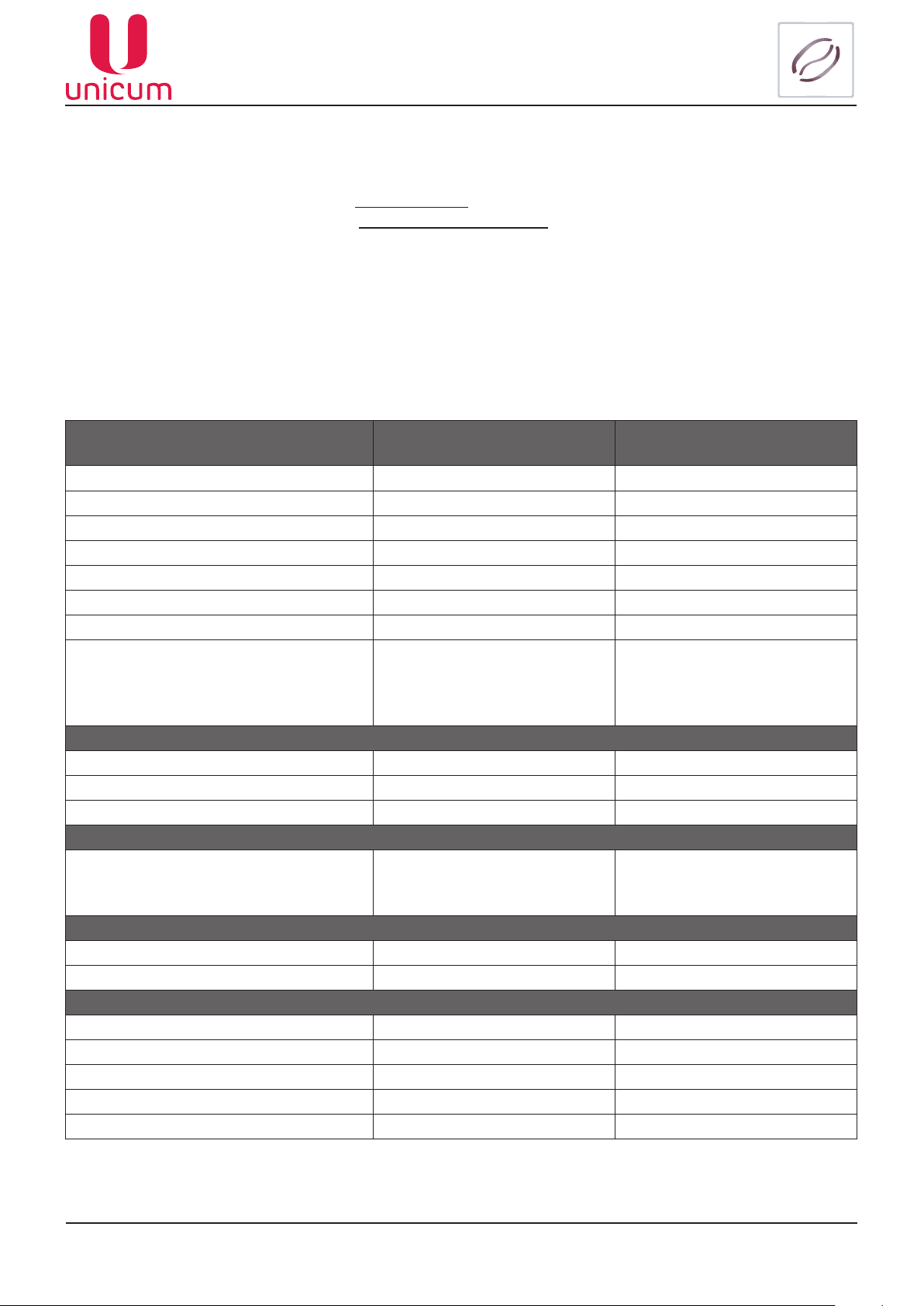
3.1 Technical features ......................................................................................................................10
3.2 Transportation and storage ........................................................................................................ 11
3.3 Installation of the vending machine............................................................................................12
3.4 The vending machine’s components..........................................................................................14
3.4.1 The vending machine’s exterior........................................................................................14
3.4.2 Internal components.........................................................................................................15
3.4.3 Open door circuit-breaker.................................................................................................17
3.4.4 Containers for ingredients and coffee beans....................................................................17
3.4.5 Cup dispenser ..................................................................................................................18
3.4.6 Spoon dispenser...............................................................................................................19
3.4.7 Cup holder........................................................................................................................20
3.4.8 Drink dispensing slot .......................................................................................................20
3.4.9 Waste container ...............................................................................................................21
3.4.10 The hydraulic circuit (for ROSSO)..................................................................................22
3.4.11 Autonomous operations, water reservoir and feed pump ...............................................23
3.4.12 Connection to water supply line (optional)......................................................................23
3.4.13 Flot chamber, pump and boiler.......................................................................................24
3.4.14 The coffee group ............................................................................................................26
3.4.14.1 Coffee grinder and dosing apparatus (for ROSSO)........................................26
3.4.14.2 Espresso group (for ROSSO).........................................................................28
3.4.15 Water selector ................................................................................................................31
3.4.16 Mixers for instant ingredients..........................................................................................31
3.4.17 Vending machine control and monitoring device............................................................33
3.4.17.1 Description ......................................................................................................33
3.4.17.2 Quick access keypad ......................................................................................34
3.4.17.3 Vending machine keypad ................................................................................34
3.4.18 RIELDA lock set..............................................................................................................35
3.4.19 Connecting SLAVE vending machines ..........................................................................36
3.4.20 Bank Note Acceptor (BNA).............................................................................................37
3.4.21 Coin slot with change dispensing function......................................................................38

ROSSO / ROSSO INSTANT
Page 5Version 3.3 / November 2016
ТМ
3.5 Vending machine’s working principle .........................................................................................39
3.5.1 Dispensing the cups .........................................................................................................39
3.5.2 Sugar and spoon ..............................................................................................................39
3.5.3 Preparation of drinks ........................................................................................................39
3.5.4 Dispensing the drink.........................................................................................................40
3.6 General technical servicing........................................................................................................41
3.6.1 Cleaning and disinfection .................................................................................................41
3.6.2 Periodic technical service.................................................................................................41
3.6.3 Flushing the vending machine’s water tract .....................................................................42
3.6.4 Weighing the ingredients ................................................................................................43
3.6.5 Cleaning the BNA ............................................................................................................43
3.6.6 Cleaning the coin slot ......................................................................................................45
4.0 SERVICE MODE .............................................................................................................................46
4.1 Technician’s menu (Service engineer’s menu) .........................................................................47
4.1.1 Menu item ‘‘1.1 SYSTEM’’................................................................................................47
4.1.2 Menu item ‘‘1.2 PAYMENT SYSTEMS’’............................................................................52
4.1.3 Menu item ‘‘1.3 TIME INTERVALS’’..................................................................................57
4.1.4 Menu item ‘‘1.4 CASH REGISTER’’ .................................................................................58
4.1.5 Menu item ‘‘1.5 MODEM’’.................................................................................................59
4.1.6 Menu item ‘‘1.6 PRICES’’ .................................................................................................61
4.1.7 Menu item ‘‘1.7 SNACK 1’’ ...............................................................................................64
4.1.8 Menu item ‘‘1.9 HOT 1’’ ....................................................................................................67
4.2 Operator’s menu .......................................................................................................................76
4.2.1 Menu item ‘‘2.1 STATUS’’ .................................................................................................76
4.2.2 Menu item ‘‘2.2 CASH’’.....................................................................................................77
4.2.3 Menu item ‘‘2.3 SNACK 1’’ ..............................................................................................78
4.2.4 Meun item ‘‘2.5 HOT 1’’ ...................................................................................................79
4.2.5 Menu item ‘‘2.7 STATISTICS’’...........................................................................................81
4.2.6 Menu item ‘‘2.8 DATA’’......................................................................................................83
4.2.7 Menu item ‘‘2.9 PRICES’’ .................................................................................................84
5.0 WORKING WITH USB FLASH DRIVE............................................................................................85
6.0 RECOMMENDED DRINK CONFIGURATIONS...............................................................................87

ROSSO / ROSSO INSTANT
Page 6Version 3.3 / November 2016
ТМ
1.0 GENERAL INFORMATION
1.1 Introduction
This user manual (hereinafter called the “Manual”) covers drinks vending machines models:
ROSSO, ROSSO INSTANT (hereinafter called the ‘‘Machine’’).
The manual contains basic information about the Machine and its software. It includes the information,
necessary for preparation for use, use and technical servicing of the Machine, as well as basic information
about the Machine’s software.
This Manual is for the technical and engineering personnel, who provide technical servicing for the Ma-
chine and are permitted to handle electrical units of similar category.
Breach of the requirements of the current Manual can lead to trauma, device damage and renders the
warranty ineffective. You must read and understand the requirements indicated in the current Manual, be-
fore installing and using the Machine, because it contains important information regarding unit safety, and
servicing and usage instructions.
The knowledge of safety requirements is necessary to instruct the users to properly use the Machine.
The Machine buyer is responsible to make sure that the serving personnel had undergone needed
training and was informed properly and that the instructions of the technical documents were fully ob-
served.
The Machine manufacturer carries no responsibility for damage or loss incurred under the following
circumstances:
• In case of unsanctioned modernization;
• In case of improper installation;
• In case of improper connection to the power and / or water supply;
• In case of cleaning and servicing contrary to the requirements;
• In case of improper operations or use of Machine’s equipment;
• In case of use of non-genuine spare parts.
• rejectionoftheuseoffoodproducts,designedspecicallyforvendingmachines.
The manufacturer of the Machine is in no case liable for any possible losses, which might result from
interruption of business due to Machine breakdown.
According to the client’s requirements the vending machine can have additional (optional) functions.
These vending machine should only be used for making and selling drinks!
1.2 Sypplementary documentation
We recommend that you read the user manuals and other associated documentation for peripheral
devices, such as cheque printer, BNA, coin slot and other devices, which are included in the machine, to
enable you to better understand the working of the vending machine.

ROSSO / ROSSO INSTANT
Page 7Version 3.3 / November 2016
ТМ
1.3 Terms of use
This Manual is for a certain version of vending machine software, which is current at the time of printing
of this Manual.
Allpossiblemodications,modernizationsand/oradaptations,whichareeffectedorwillbeexecutedin
future for following sales, do not mandate the manufacturer to conduct similar modernization of software
for the earlier sold Machines, as well as it does not mandate the manufacturer to amend the user docu-
mentation, which is a part of the Machine’s package.
The developer of the Machine and regulatory software have the right to make necessary changes to the
Machine’sstructure,software’sowandinthedocumentationforitsusewithoutnoticetotheuser.
1.4 Manufacturer’s warranty
The manufacturer’s warranty during the warranty period covers all vending machine units and assem-
blies,
except for malfunctions, arising from non-observance of current maintenance documentation
requirements by the customer or due to any mechanical failures.
The following components are excluded from the manufacturer’s warranty:
•gaskets;
•fuses;
•controlboardsbatteries;
•mixerimpellers;
•hydraulicsystemtubes.

ROSSO / ROSSO INSTANT
Page 8Version 3.3 / November 2016
ТМ
2.0 SAFETY
2.1 Main provision
• Before the installation and usage of the vending machine, it is necessary to carefully read and
understand all the instructions, contained in the current manual, because they embody important
information regarding safety of the unit, its operations and technical servicing.
• The vending machines should not be subjected to negative temperatures during operations and
storage.
• These vending machines should not be installed in open air.
• Thevendingmachinesshouldbeinstalledandifnecessaryrepairedonlybyqualiedpersonnel,
whohaveundergonetrainingtohandlethemachinesandtheirconstituentpartsandareprocient
in safety procedures. The vending machines should be connected to water supply and power sup-
ply in conformity with the applicable rules (standards) of the country in which they are installed.
• The vending machines should be installed on an even surface, where the angle of vertical inclina-
tion should be less than 2O. You can use the adjustable pegs of the machine to achieve desired
verticalinclination.Thesepegsareincludedinthemachine’sbaseconguration.
• The vending machines should be connected only to protected power supply with earthing.
• The power plug of the machine should be approachable (accessible) after the machine has been
installed.
• If the power cable would be damaged, it should immediately be replaced. It is strictly PROHIBITED
to use the vending machine with damaged power cable!
• Thevendingmachinesshouldbecleaned,lledandinstalledonlybyqualiedpersonnel.
• It is strictly prohibited to clean the vending machine using a water jet and the machines should not
be installed in locations, where water jets are used (for example for cleaning).
• You should always use genuine spare parts.
ATTENTION: Do not touch the power plug with wet hands and do not insert it into the socket
if the plug is wet!
ATTENTION: Please check the quality of drinking water used in the vending machine. The
vending machine must be connected to the water supply according to the instructions issued
by the competent authorities and in accordance with local rules!
Please make sure that the voltage in the power mains is compliant with the permissible value
indicatedonthemachine’sspecicationplate!
Please wash the vending machine before putting it to use!

ROSSO / ROSSO INSTANT
Page 9Version 3.3 / November 2016
ТМ
• Regularly clean the vending machine, to adhere to the hygienic safety rules.
• Please only use washing materials, permitted for use in food preparation areas, to clean the
vending machine’s body.
• Make sure that the vending machine is OFF before starting technical service or repair.
• It is strictly prohibited to cover the vending machine with fabric or any other such material.
• Eachvendingmachineisidentiedbytheserialnumberinscribedon thespecicationplate,
whichisttedontherearwallofthemachine.Thespecicationplatescarriesallthetechnical
details of the machine.
ATTENTION:Thevendingmachinedispenseshotdrinks!Thefrontapofthedispensingslot
should be closed during the preparation of the drinks to avoid burning hands or other parts of
body!Pleasedonotopenthefrontapbeforethedrinkisreadyfordispensing!
ATTENTION: This vending machine only be used inside covered premises!

ROSSO / ROSSO INSTANT
Page 10Version 3.3 / November 2016
ТМ
3.0 PURPOSE
The ROSSO and ROSSO INSTANT vending machines are designed to prepare and sell drinks:
• Hot drinks using coffee beans (Model ROSSO);
• Hot drinks using instant coffee (Model ROSSO INSTANT);
• Hot drinks made of instant ingredients
The ingredients that you use for making the drinks, must be declared by the ingredient manufacturer as
tforuseinopencontainers.
3.1 Technical features
Thevendingmachine’smaintechnicalspecsareinscribedonthespecicationplate.
Parameters ROSSO ROSSO INSTANT
Height(А),maximum 1850 mm 1850 mm
Width(В),maximum 600 mm 600 mm
Depth(С),maximum 670 mm 670 mm
Weight, maximum 130 kg 130 kg
Voltage 220 -230 V 220 -230 V
Power frequency 50 Hz 50 Hz
Power consumption (max) 1800 W 1800 W
Consumption of electricity per day,
when surrounding air temperature
is 220C and making 40 drinks (each
100ml), maximum permissible (*)
4 kWh 4 kWh
External water supply
Water pressure, minimum 0.5 bar (0.05 MPa) 0.5 bar (0.05 MPa)
Water pressure, maximum 8.5 bar (0.85 MPa) 8.5 bar (0.85 MPa)
Connection to water supply line G 3/4’’ G 3/4’’
Internal water supply
Standart cans / bottles (not included in
the package)
2х20L(max.) 2х20L(max.)
Recommended parameters of water
Hardness 0.9 - 1.0 mgeq/l 0.9 - 1.0 mgeq/l
Calcium 18 - 20 mg/l 18 - 20 mg/l
Cup and spoon dispemser
Quanity of cups (max) 600 pcs 600 pcs
Cup diameter 70 mm 70 mm
Cup’s volume 160 -180 ml 160 - 180 ml
Quanity of spoons (max) 600 pcs 600 pcs
Spoon size (**) 95 / 105 / 115 mm 95 / 105 / 115 mm

ROSSO / ROSSO INSTANT
Page 11Version 3.3 / November 2016
ТМ
Parameters ROSSO ROSSO INSTANT
Number of containers
Coffee bean container 1 pcs -
Instant ingredients container 4 pcs 5 pcs
Sugar container 1 pcs 1 pcs
Volume of containers (***)
Volume of container for loose ingredients
5.2 l ±5% 5.2 l ±5%
Coffee beans 5.0 kg -
Instant coffee - 1.4 kg
Powdered milk 2.2 kg 2.2 kg
Chocolate 4.8 kg 4.8 kg
Tea 5.2 kg 5.2 kg
Vanilla cappuccino 4.8 kg 4.8 kg
Sugar 4.0 kg 4.0 kg
*) The estimated power consumption indicators are average numbers and are shown only as reference
points;
**) 105mmisthestandardcongurationofthespoon;
***) Thequantityofingredientscanbedifferentfromtheoneshowndependingonthespecicweightof
the ingredient.
3.2 Transportation and storage
All transportation and storage procedures should be executed very carefully to avoid damaging the
vending machine. All the operations related to lifting and displacement of the vending machine should be
executed using a fork lift. The forks of the lift should be slipped under the vending machine at the spots
indicated on the machine’s packing.
The following should be observed during the vending machine’s transportation:
• The vending machine should be transported only in the original packing;
• The vending machine should be transported in strictly vertical position;
• Thevendingmachineshouldnotbetiltedandturnedorippedover
• It is not permissible to lift the machine from the side walls;
• It is not permissible to lift the vending machine using ropes, cables etc.
The vending machine should be stored in dry premises where air temperature is in the range of 1 to
40OC and level of humidity is no more than 80%.
It is prohibited to stack the vending machines on top of each other in storage. The vending machines
should be stored in vertical position in original packing.

ROSSO / ROSSO INSTANT
Page 12Version 3.3 / November 2016
ТМ
3.3 Installation of the vending machine
The ROSSO and ROSSO INSTANT vending machines cannot be installed in open air. The vending
machines should be installed in dry premises with temperatures ranging from 5Oto 30OC.
Thevendingmachineshouldbeinstalledatadistanceof5cmfromthewalltoprovideforsufcient
ventilation.
The vending machine must not have a vertical tilt of more than 20.
Please remove the packing and take out the master-key from the change dispensing slot. Using this
key program the machine’s lock. Then using the functional key open the vending machine’s door (the key
isstuckinsidethechangedispensingslotusingscotchtape)–(seesection3.4.19andgures1,2,3).
Figure 1 Figure 2 Figure 3
The vending machine’s inner components are all wrapped in packing. Before turning the machine ON
please make sure that all of the packing materials have been removed. You can see the spots where the
packingiswrapped,indicatedbyarrowsingures4and5.
Figure 4 Figure 5

ROSSO / ROSSO INSTANT
Page 13Version 3.3 / November 2016
ТМ
Theliquidwastecontainerisxedonthelowerpartofthe
machine’s body with the help of plastic studs. Remove the
studs(seegure6).
Thenremovethepacket(seegure7),whichisinsidethe
container.Thispacketcontainsallthexturesneededfor
installation(seegure8).
Figure 6 Figure 7
1. Power cable
2. Set of adjustable pegs
3. Passport
4. Weights for spoons
5. Fixtures for piqued waste container
6. Clamp for waste coffee collector
7. Electric circuit-breaker key
ThevendingmachineisxedtothecarriertrayusingM10screws.Removethescrewsandinstallthe
adjustable pegs. You can adjust the vertical tilt of the machine using these pegs.
Afteradjustment.Pleasecoverthepegsusingdecorativecasing,asshowningures9,10,11.
Figure 8
Figure 9 Figure 10 Figure 11
Thevendingmachinemustbeinstalledandservicedonlybyqualiedandauthorizedpersonnel,who
have undergone training to operate and service the given class of machines.
The packing materials should be utilized in accordance with the environmental laws of the locality of
installation.
4
5
6
7

ROSSO / ROSSO INSTANT
Page 14Version 3.3 / November 2016
ТМ
3.4 The vending machine’s components
The ROSSO and ROSSO INSTANT vending machines come in the shape of rectangular metallic boxes
of the following dimensions (max):
- Height 1850 mm
- Breadth 600 mm
- Depth 670 mm
The body houses various functional units of the vending machine. The body is closed with a metallic
door, which has decorative plastic components.
The door contains the following equipment:
- Money intake and refund devices;
- Indicator panel;
- Drinks dispensing slot;
- Drink selection buttons;
- Change return button;
- Sugar quantity adjustment button;
- Light panels
3.4.1 The vending machine’s exterior
The vending machine’s metallic door is made of 1mm
thick steel and has decorative plastic components. The door
carriesthefollowingmaincomponents(seegure12).
1. Upper and lower light-boxes, with LED lights. The upper
light-box can optionally be replaced with a video monitor.
2. Drinks selection keypad, which can also hold labels with
product name.
3. Theprotectiveplasticapforthedrinksdispensingslot.
4. The “MIZMATIC” programmable lock.
5. Bank note acceptor (BNA).
6. 4 row contrast character display.
7. Sugar level adjustment button (“+” / “-“)
8. Coin deposit slot and change dispensing button.
9. Change (coins) dispensing slot.
10. Decorative replaceable panel, which covers the adjust-
able pegs.
Figure 12
The following components are located on the rear outer
wall of the vending machine.
CAN BUS connector to connect FoodBox Slave / FoodBox Long
Slave vending machines: position 1.
Power cable connector: position 2
A ¾” threaded connector to connect with water supply (optional)
1
1
2
3
4
5
6
7
8
9
10
Figure 13 Figure 14

ROSSO / ROSSO INSTANT
Page 15Version 3.3 / November 2016
ТМ
3.4.2 Internal components
а.Body
The vending machine’s body contains: drinks preparation units, containers for ingredients, waste con-
tainers, payment systems, circuit boards used to control the vending machine’s functioning and space for
the installation of 2 (two) bottles / cans of water.
The dispensers for cups and spoons, container for sugar and drinks dispensing section are all placed
on a swinging bracket. The control panel and payment system are protected by a metallic box and are
situated on the inner-side of the door.
Figure 15 (description):
1. Cup dispenser;
2. Container for sugar;
3. Coffee bean container (ROSSO);
4. Container for loose ingredients;
5. Coffee grinder (ROSSO);
6. Coffee dosing apparatus (ROSSO);
7. Mixers;
8. Espresso group (ROSSO);
9.
Pipes to supply dissolved ingredients into the cup;
10. Boiler cover
11. Coffee waste dispensing tube (ROSSO);
12.
Space for the installation of can/bottles of water;
13. Water supply pump for autonomous functioning;
14. Fan for drying mixer nozzles;
15. Waste container (in front of bottles);
16. Protectivehousingforpowersupply(seegure18).
Theoatchamberandwaterselectorarelocatedbe-
hind the coffee bean container (see section 3.4.17).
Figure 16
Figure 15
1 2 3 4
5
6
7
8
9
10 11
12
13
14
15
16
The waste container is situated in the low-
er part of the machine’s body. The body
also has space for the placement of two
20 litre each bottles or cans of water of
volumes (not supplied with the machine).

ROSSO / ROSSO INSTANT
Page 16Version 3.3 / November 2016
ТМ
The drinks dispensing tray is placed on a swinging bracket.
The dispensers for cups, spoons and sugar container are all situat-
ed above the drinks dispensing tray.
The drinks dispensing tray includes the following components (see
gure17):
1. Cup, sugar and spoon dispensing slot
2. Optic sensors (optional)
3. Turning handle to displace the cup (cup movement)
Figure 17
b. Door
The vending machine’s door is equipped with money intake
and change dispensing devices, indicators, drinks selection
buttons, change dispensing button, sugar level adjustment
button,lightpanelanddrinksdispensingslot(seegure19).
1. Door to the electronic circuitry section
2. Upper light-box cover
3. The keyboard short cut
4. Drinks selection keypad – label placement slot (back side)
5. Electronic circuitry section door latch
6. Drinks dispensing slot (back side)
7. Lock mechanism
8. Bank note acceptor (BNA)
9. Main Board (controller)
10. Modem (optional)
11. Coin slot with change dispensing function
12. Coin box (cash box)
Figure 18
1
2
3
The power supply and the power supply circuit are located on the
rear wall of the body behind the containers with ingredients.
с.Powersupply(1),powercircuit(2)
To access the power supply section,
please remove the ingredient con-
tainers and loosening the screws,
remove the protective panel.
The extension block with multiple
sockets (3), used to connect acces-
sories (printer, speakers) is located
on the top end (optional)
Figure 19
1
2
3
1
2
3
4
5
6
7
8
9
10
11
12

ROSSO / ROSSO INSTANT
Page 17Version 3.3 / November 2016
ТМ
3.4.3 Open door circuit-breaker
A special circuit-breaker turns OFF all power to the electrical and electronic system, when the door
is opened, to ensure that all the operations related to the recharging (loading) and cleaning would be
carried-out under completely safe conditions. All other operations behind the door, which need to be per-
formedwiththerunningpower,mustbeperformedEXCLUSIVELYbyqualiedpersonnel,whohaveper-
mission to perform such works and who know all the risks involved in the performance of such works.
Figure20а Figure 20b Figure 20c
To turn ON the power, with the door
open, it is necessary to insert the spe-
cialkey(seegures20a,b,c)intothe
breaker and turn it through 900until it is
xed.Pleasemakesuretoremovethis
key before closing the door.
3.4.4 Containers for ingredients and coffee beans
Thedrinkvendingmachinehastwotypesofcontainers:containersforingredientsandsugar(seegure
22)andcontainerforcoffeebeans(fortheROSSOmodel)(seegure21).
Figure 21
Filling the coffee beans container
Tollthecontainer,pleaseremovethetoplidofthecontainer(seegure23)andllitwithcoffeebeans
(seegure24).
Thecoffeebeancontainerhasaxinglatch(seegures25,26).Toremovethecontainer,forexample
toaccesstheoatchamberorwaterselector,pleaseclosethecoffeefeedholeswiththelatchandremove
the container. After reinstalling the container make sure to fully release the latch to free the passage of
coffee beans.
Figure 22

ROSSO / ROSSO INSTANT
Page 18Version 3.3 / November 2016
ТМ
Figure 23 Figure 24 Figure 25
Figure 26
Figure 27 Figure 28
Filling the ingredient containers
The ROSSO vending machine has 4 containers for
powderedingredients(seegure27),whereasROS-
SO INSTANT has 5 containers.
Tollthecontainers,justpickthelidoffthecontainer
andllitfromthetop(seegure28).
ATTENTION: Please make sure that no foreign ob-
jectsgo inside thecontainer during rell.Alsomake
sure that the ingredients are not compacted (lumped)
duringrell.
Please remove the excess of ingredients from the out-
er walls of the containers and other parts of the vend-
ing machine.
There is a reducer-motor behind each of the containers, which is used
to feed the ingredients into the mixer.
Thequantityoftheingredientisxedinthedrink’srecipe.Thequantity
means the time of rotation of motor, which is installed behind the contain-
er, in tenths (1/10) of seconds.
Ifneeded(forconvenienceinrellingthecontainers)thecontainers
can be removed:
Turn the spout upwards and slightly raise the container with the help of
the spout to ensure that the container’s bottom is free of the holder. Then
pull the container out.
The sugar container is located near the cup dispenser (see gure
3.4.4).Thiscontainershouldberelledinthesamemannerastheother
containers (see above).
3.4.5 Cup dispenser
Thecupdispenseristtedonaswingingbracket.Thedispensercanhold
upto600cupsin5tubes(seegure29).Thedispensersequentiallyre-
leases cups from all tubes.
Fillingthevacanttubeswithcups(seegures31а,31b):
• Turn OFF the vending machine
• Remove the dispenser’s upper lid
•
Load the cups (bottom down) only in the tubes, which are not (even
partially) above the dispensing cavity
Figure 29
Container
for sugar
Cup dispenser
Spoon dispenser
The mechanism of
the dispenser cup

ROSSO / ROSSO INSTANT
Page 19Version 3.3 / November 2016
ТМ
• Turn ON the vending machine and wait till the stack of cups falls into the dispenser following the
automatic rotation of tubes and the rotation of tubes stops.
• Makesurethatthelowestcup(rsttofall)inthenewstackisstrictlyvertical(withoutanybendsor
tilts). If there is any vertical tilt, please adjust it by raising the stack from below and then replacing it.
• Add cups to the rest of the vacant tubes and replace the lid.
Figure31а Figure31б
NOTE: To install the tubes on the cup dispenser
mechanism, turn aside the spring (see gure 30b)
andinstallthetubes(seegure30c).
ATTENTION: Incorrectinstallationoftubes(seeg-
ure 30d) can damage the dispensing mechanism! It
is strictly prohibited to rotate the tubes manually, be-
cause this would damage the tubes’ rotation mecha-
nism!
3.4.6Spoondispenser(seegure29)
Thespoonsaredispensedinaccordancewiththecongurationsoftheservicemenu.YoucanturnOFF
the dispensing of spoons or only turn it ON for drinks with added sugar.
Figure 32
Figure 33
Figure 34
Thedispensercanberelledfromthetop(seegure32).
Place the spoons in the dispenser’s column without packing
(seegure32),thenplacethetwometallicweightsontop
of the spoons.
These weights are supplied with the vending machine.
The dispenser can hold spoons of the following three
lengths: 95mm, 105mm, 115mm.
The dispenser’s maximum capacity is 600 spoons.
The vending machine comes with the dispenser set for
105mm spoons.
To adjust it for spoons of 95mm or 115mm, please adjust the
guide,asshowningures33and34.
30а 30b
30c 30d

ROSSO / ROSSO INSTANT
Page 20Version 3.3 / November 2016
ТМ
Thecupholder(seegure35)isinstalledontherotatingjointofthemechanicalarm.Afterthedrinkhas
been selected, the cup falls into the cup holder and then sugar and spoon fall into the cup. After this the
cup holder moves the cup into the vending machine’s body for safe preparation of drink.
3.4.7Cupholder(seegure35)
3.4.8 Drink dispensing slot
Thebodyofthedispensingareaismadeofmouldedplastic(seegure36)andisinstalledinthefront
part of the swinging bracket under the cup dispensing cavity.
Figure 36
The dispensing area is equipped with a removable tray with a grill, which
is located right under the cup holder. The tray serves as a store for spilt over
drinks and liquids. To clean or change the plastic components it is necessary
toremovethetrayandthegrilltowipeoutorcollectliquidwaste(seegures
37, 38, 39).
Figure 37
Figure 38 Figure 39
Figure 35
The cup with ready drink is brought out by the rotating arm within the range
of the optical sensors (if installed). The optical sensors record the removal of
cup by the customer. The use of optical sensors enables the customers to use
their own cup for drinks. To do this you must place the cup inside the cup holder
before selecting the drink. When the vending machine senses the presence of
a cup it will not dispense a new cup.
This manual suits for next models
1
Table of contents
Other Unicum Vending Machine manuals
Popular Vending Machine manuals by other brands

Intralot
Intralot Dreamtouch Smart manual

Fastcorp
Fastcorp EVOLUTION FS-01 Setup and user guide

Intralot
Intralot WinStation manual

EVOCA
EVOCA Krea Touch Installation - use - maintenance

Automatic Products
Automatic Products SNACKSHOP 113 instruction manual

Crane
Crane Dixie-Narco 504 P Series Technical manual