EnglishDeutsch
 logo
Brands
  1. Home
  2. •
  3. Brands
  4. •
  5. Unit
  6. •
  7. Test Equipment
  8. •
  9. Unit UT502A User manual

Unit UT502A User manual

Other Unit Test Equipment manuals

Unit UT590 Series User manual

Unit

Unit UT590 Series User manual

Unit UT581 User manual

Unit

Unit UT581 User manual

Unit utd2000 User manual

Unit

Unit utd2000 User manual

Unit UPO1000 Series User manual

Unit

Unit UPO1000 Series User manual

Unit utd2000 User manual

Unit

Unit utd2000 User manual

Unit UT-586 User manual

Unit

Unit UT-586 User manual

Unit UT261 Series User manual

Unit

Unit UT261 Series User manual

Unit UT521 User manual

Unit

Unit UT521 User manual

Unit UT512D User manual

Unit

Unit UT512D User manual

Unit UT527 User manual

Unit

Unit UT527 User manual

Unit UT3500 Series User manual

Unit

Unit UT3500 Series User manual

Unit utd2000 User manual

Unit

Unit utd2000 User manual

Unit UT 4000 Series User manual

Unit

Unit UT 4000 Series User manual

Unit UT3200+ Series User manual

Unit

Unit UT3200+ Series User manual

Unit UPO2000E Series User manual

Unit

Unit UPO2000E Series User manual

Unit UTL8200 Series User manual

Unit

Unit UTL8200 Series User manual

Unit UTD1000 Series User manual

Unit

Unit UTD1000 Series User manual

Unit UT522 User manual

Unit

Unit UT522 User manual

Unit UT501A User manual

Unit

Unit UT501A User manual

Unit UT12A User manual

Unit

Unit UT12A User manual

Unit UT361 User manual

Unit

Unit UT361 User manual

Unit MSO Series User manual

Unit

Unit MSO Series User manual

Unit UT-513A User manual

Unit

Unit UT-513A User manual

Unit UT279 User manual

Unit

Unit UT279 User manual

Popular Test Equipment manuals by other brands

SMART KANAAD SBT XTREME 3G Series user manual

SMART

SMART KANAAD SBT XTREME 3G Series user manual

Agilent Technologies BERT Serial Getting started

Agilent Technologies

Agilent Technologies BERT Serial Getting started

Agilent Technologies N3280A user guide

Agilent Technologies

Agilent Technologies N3280A user guide

Lifeloc R.A.D.A.R. quick start guide

Lifeloc

Lifeloc R.A.D.A.R. quick start guide

Fluke T5-600 Service information

Fluke

Fluke T5-600 Service information

Mercury TSL01 user manual

Mercury

Mercury TSL01 user manual

MAHA MBT Series Original operating instructions

MAHA

MAHA MBT Series Original operating instructions

Fuji Electric P-61 instruction manual

Fuji Electric

Fuji Electric P-61 instruction manual

ETC SealerAtor user manual

ETC

ETC SealerAtor user manual

Skyfine ETHYWAY V2 user manual

Skyfine

Skyfine ETHYWAY V2 user manual

Appion G5 Twin Operation manual

Appion

Appion G5 Twin Operation manual

PCB Piezotronics 8159-0112A Installation and operating manual

PCB Piezotronics

PCB Piezotronics 8159-0112A Installation and operating manual

BW Technologies MicroDock II user manual

BW Technologies

BW Technologies MicroDock II user manual

Sun Nuclear 1027 user guide

Sun Nuclear

Sun Nuclear 1027 user guide

Biomark HPR LITE READER user manual

Biomark

Biomark HPR LITE READER user manual

Hioki 3169-20 instruction manual

Hioki

Hioki 3169-20 instruction manual

Ashcroft ATE-100 operating manual

Ashcroft

Ashcroft ATE-100 operating manual

Rohde & Schwarz RTA4000 user manual

Rohde & Schwarz

Rohde & Schwarz RTA4000 user manual

https://manuals.online logo
https://manuals.online logoBrands
  • About & Mission
  • Contact us
  • Privacy Policy
  • Terms and Conditions

Copyright 2026 Manuals.Online. All Rights Reserved.

UT502A Insulation Resistance Tester is designed with brand-new
design and combination of massive integrated and digital circuits; it
can measure insulation resistance, low resistance, AC voltage, etc,
and enjoys high degree of accuracy, stable performance, easy
operation and reliability. It is used for insulation resistance
measurement for insulation materials and various kinds of electric
equipments such as transformer, electric machines, cables, switches,
electrical appliances, a ideal tool for electric equipment maintenance,
testing and inspection.
2. Safety Information
The instrument is designed and manufactured in compliance with
IEC61010 standard. The manual covers safety information related to
the safe operations and conditions of the instrument. please read
carefully before using the instrument.
Warning
Use always as specified in the manual, and keep it for future use.
conditions and actions that may cause serious or
fatal damage.
Alerts users to avoid electric shock.
conditions and actions that may cause damage to
the instrument or affect accurate measurement.
voltage over 750VAC.
leads
When test leads are shorted and connected to the instrument, do
not press TEST key.
during test.
Do not touch the tested line during insulation measurement.
Eg: the
instrument was damaged or had exposed metal.
is
discharged.
between test leads
lead
lead
low battery indicator shows If
properly.
3. Electrical Symbols
Risk of electric shock
Accuracy: ±(a% of reading + b digits), calibration per year.
Insulation Resistance Measurement
Polarization Index/Dielectric Absorption Ratio Measurement
Low Resistance Measurementc
Open-circuit voltage
Measurement range
Resolution ratio
Accuracy
Approx. 5.0V
0.00~200Ω
0.01Ω
± (2%+3)Ω
Criterion Best
Best
Good
Good
Bad
Bad
DAR Value
Criterion
DAR Measurement
DAR Measurement
PI Measurement
PI Value
10min insulation resistance/1min insulation resistance
Greater than
or equal to 4 4---2 2.0---1.0 Less than or
equal to 1.0
Warning
Greater than
or equal to 1.4 1.25--1.0 Less than or
equal to 1.0
1min insulation resistance/30s insulation resistance
1min insulation resistance/15s insulation resistance
500V 1000V 2500V
Rated voltage
Short circuit current
Accuracy range
Measurement
range
Open circuit
voltage
Rated measurement
current
0.00MΩ ~ 5.00GΩ 0.00MΩ ~ 5.00GΩ 0.00MΩ ~ 20.0GΩ
DC 500V+10% DC 1000V+10% DC 2500V+10%
Under 500KΩ
1.00mA~1.10mA
Under 1MΩ
1.00mA~1.10mA
Under 2.5MΩ
1.00mA~1.10mA
Approx. Less than 1.8mA
0.00MΩ~99.9MΩ: ±(3%+5)
100MΩ~10GΩ: ±(5%+5)
10.0GΩ~20.0GΩ: ±(10%+5)
Voltage Measurement
AC voltage
Measurement range
Resolution
Accuracy
30~750V (50/60Hz)
1V
±
(2%+3)
Low battery indication: .
Overload indication: ">22.0GΩ" shows under insulation
resistance measurement.
display the unit and function simultaneously
●Automatic voltage release
●Backlight for work on dark sites
●Red light for warning
(Altitude: <2000m)
under normal condition)
operating manual, carrying case.
test leads,
●Safety compliances: Overvoltage CATIII 600V, Pollution
Degree 2 as per IEC61010
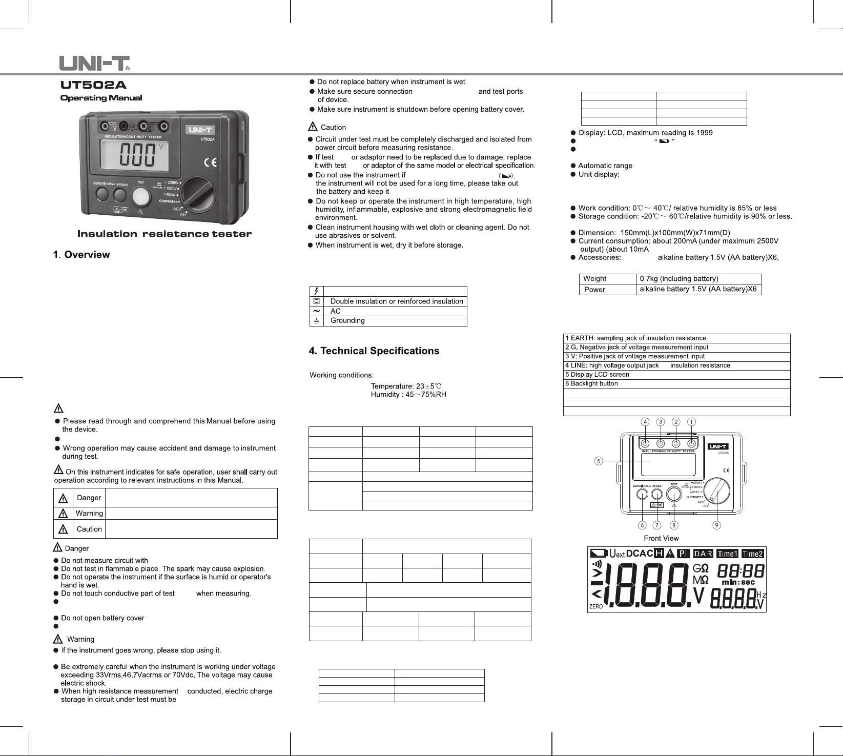
5. Tester's Structure(Front View)
measurement
for measurement
7 Switch button for PI/DAR
8 TEST button
9 Rotary knob
LCD Display
6. Buttons and Rotary Knob
1. PI/DAR button: measures polarization index/dielectric absorption
ratio.
2. ZERO/LIGHT button: turns on/off the backlight or resets the
display to zero for low resistance measurement.
3. TEST button: turns on/off insulation and low resistance
measurement.
4. Rotary knob set to ACV: to measure AC voltage.
5. Rotary knob set to CONTINUITY: to measure low resistance.
P/N:110401104398X
6. Rotary knob set to 500V/1000V/2500V:
to select test voltage for insulation resistance measurement.
If low battery indicator shows on upper left corner of LCD after the
meter is turned on, it means battery is almost used up and need to
be replaced.
(See Figure 1)
Figure 1
(1) Set the rotary knob to ACV.
(2) Insert the red test lead into "V" jack and the black test lead into
"G" jack.
Disconnect test leads and tested circuits and remove test leads
away from input jacks after completing the measurement.
Please take extreme caution in order to avoid electric shock when
measuring high voltage.
(See Figure 2)
With the instrument connected to tested circuit as described above,
lead lead
test probe with the circuit
under test.
Figure 2
(See Figure 3)
Figure 3
● Turn the knob to select test voltage 500V/1000V/2500V.
Do not short-circuit the test leads under high-voltage output status or
make insulation measurement after high voltage has already been
output.
lead lead
With the knob already set to test voltage 500V/1000V/2500V, then
press TEST button,the instrument will be self-locked to measure
continuously. The test voltage will be output and TEST button will
light up. With the measurement finished, press TEST button to
unlock and stop the measurement.
When red and black clips are connected to the circuit under test,
high voltage is output from LINE jack and the current from EARTH
jack.
Dielectric absorption ratio measurement
Under insulation measurement mode, press PI/DAR button two
times to select DAR parameter, the screen displays Time 1(30s)/
Time2(1min), then press TEST to start DAR measurement. Press
TEST three times to select another DAR, the screen shows Time
1(15s)/Time2(1min), press to begin another DAR measurement.
Under insulation measurement mode, press PI/DAR button once
to select PI parameter, the screen displays Time 1(1min)/
Time2(10mins), then press TEST to start PI measurement.
replacing
batteries
installing
set the knob to
the housing
To avoid damage to the instrument, do not submerge it into
the water.
Clean the instrument surface with soft cloth or sponge
dampened with clean water.
When it is necessary to verify or repair instrument, please
deliver the instrument to qualified professional serviceman
or designated repairing department.
M
R
*END*