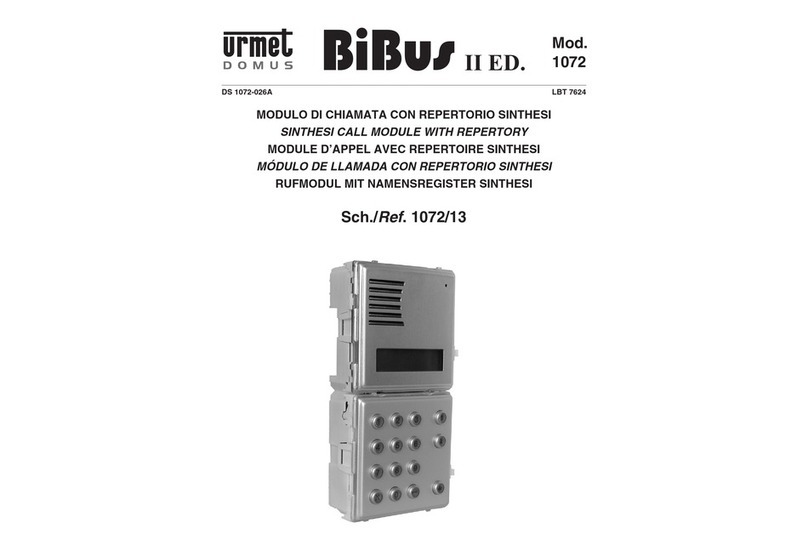
DIGITALIZER REF. 1052/7R
PROGRAMMING
3
PROGRAMMING
AUDIO VIDEO SETTINGS
Audio Video settings should be done after digitizer is programmed
and it should be performed in normal work mode (without pressing
confirmation button or entering into programming menu).
After choosing one of these two modes it is required to remain dip-
switches positions for all work time of the device. Changing dip-
switches position may change work Audio Video mode of digitizer.
After setting Audio Video mode with dip-switches, confirmation is
not required. Change of dip-switches position will change digitizer
work mode immediately.
Digitizer can work in 1 of 2 available modes:
•Audio-Video mode (when digitizer work in video system).
•Audio mode (when digitalizer work with only audio panel eg.
MIWUS 525).
After all programming is finished depending on digitizer work mode
(audio only or audio video) it is required to:
1. Audio only – dip-switches 1-9 set to OFF position,
2. Audio-video – dip-switch number 1 set to ON, dip-switches 2-9
set to OFF.
NOTE:
After audio-video settings,
should you leave the dipswitch
settings (any changes in the dipswitch settings at
normal work will change audio-video settings).
By
normal work of digitalizer, do not change dip-switches
position.
ID SETTING
ID is important only for multi-entry systems and for a group of
digitizers. In normal installation (with one entrance panel) this step
should be skipped.
Digitizer has a pre-assigned ID of 8 - 248, except that it is a value
divisible by 8. ID must be unique for each call module (other
digitalizers and call modules with keyboard).
To change ID follow the steps below:
•Use (ADRES) dip-switches 4 to 8 to set binary number of ID
from a range between 8-248 (must be divisible by 8).
Remember that dip-switch number 4 is the least valuable bit
and mean 8 (in decimal) and dip-switch number 8 is the most
valuable bit and mean 128 (in decimal). Rest of dip-switches
should be in OFF position. ADDRESS dip-switch in ON
position mean 1, but in OFF position mean 0.
•Press and hold for 4-5 seconds button PROG, until come on
red LED.
•If ID number is correct, call module generates confirmation
signal, red LED will be turned off. If ID will be not approved (for
example because of two the same ID number) call module will
generate warning signal, LED will start blinking for 3 seconds.
SETTINGS GROUP OF DIGITIZERS
Single digitizer can be programmed with 21 buttons. If panel has
more than 21 buttons , a group of digitizers have to be created.
Single group (up to four digitizers) can handle up to 84 (4 * 21)
buttons. A single power supply can fully support a single group (84
entries). In a single group voice, electronic lock or key reader are
supported by a main digitizer (one with ID divisible by 8). Group ID
can be set using ADRES dip-switches from 4 to 8 and an address
of a digitizers inside group by dip-switches 1 and 2 where 1 is least
significant bit and 2 is most significant bit (see appendix).
Within that group are the main digitizer, first, second and third. In
the group may also be less than four devices.
When a group is created it should be noted that the ID of
another device (or other digitizer panel) is not covered with the
ID of the group.
To program a group of digitizers follow the steps below:
•To set an ID for the main digitizer use ADDRESS dip-switches
4-8 to set binary number of ID. Remember that dip-switch
number 4 is the least valuable bit and mean 8 (in decimal) and
dip-switch number 8 is the most valuable bit and mean 128 (in
decimal). Other dip-switches (1,2,3 and 9) must be set in OFF
position.
•Press and hold for 3 seconds button PROG, until come on red
LED.
•If ID number is correct, call module generates confirmation
signal, red LED will be turned off. If ID will be not approved (for
example because of two the same ID number) call module will
generate warning signal, LED will start blinking for 3 seconds.
•To set an ID of the first, second and third digitizer in the group
set switches from 4 to 8 exactly like in the main digitizer. Then
set switches 1 and 2 respectively to the digitizer number in the
group. e.g. first digitizer (1-On, 2- Off), second digitizer (1-0ff,
2-0n), third digitizer (1-On, 2-On)
Example
We want to establish a group of 3 digitizers.
1. We set the ID of the main digitizer. ID to select from a pool of 8
to 248, e.g. 16 (must be divisible by 8).
2. On Address dip-switches set binary 16 (dip-switches no. 1 to 4
in the OFF position, dip-switch No. 5 in the ON position, dip-
switches 6 to 9 in the OFF position).
3. Press the PROG button and keep it pressed until the LED glow
(about 4 - 5 seconds).
4. Release the PROG button.
5. We come to the next digitizer and set the ID - this will be the
first digitizer. Dip-witch no. 1 set to ON, dip-switches 2 to 4 to
OFF, dip- switch no. 5 to ON, dip-switches 6 to 9 to OFF.
6. Press the PROG button and keep it pressed until the LED glow
(about 4 -5 seconds). When properly programmed, the panel is
connected to the main digitizer generates a beep.
7. Release the PROG button.
8. We come to the next device and set the ID - this will be the
second digitizer. Dip-witch no. 1 set to OFF, dip-switch 2 to
ON, dip-switch 4 is OFF, dip-switch no. 5 to ON, dip-switches 6
to 9 to OFF.
