21
DS1083-051A
CONFIGURATION PARAMETERS
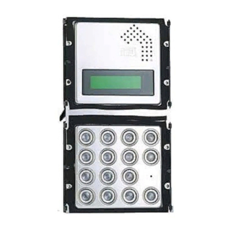
To access the conguration menu, enter the code 99999 followed by the password (default 1000) and the
key. Then, press the key and press .
Press to conrm selection; press X to cancel selection. Pressing X for 3s returns to the start of the menu;
to quit, press X again.
Module type
The calling module may be a main or secondary device. All systems users can be called from the main
device; only users of the related riser column can be called from the secondary device. The user who
receives the call is able to distinguish the origin of the call according to ring duration.
There may be 2 secondary call stations with different numbers in the same riser column (secondary 0 or
1).
Module ID: door unit number
Set a number from 00 to 03 for a main module or from 00 to 31 for a secondary module.
Two main stations cannot have the same ID. Two secondary stations may have the same ID but must
have a different number (see next parameter).
The ID of the secondary door unit must be the same as the riser column ID set in the Ref. 1083/50
riser column interface.
Secondary
In the case of a secondary module and if there is only one secondary in the riser column, set 0; if there are
2, set 0 and 1 in the two secondaries.
Code type
Type of user call code.
Physical code: users are called with a 5-digit code as follows: ccnnn, where cc indicates the riser
column (from 00 a 31) and nnn indicates the number of the apartment (from 000 a 127)
Logical code: users are called with a a number of 1 to 4 digits from 1 to 9999. To use the logical
codes, the names must be programmed, assigning the logical call code to the physical code of the
apartment.
Device type
Indicates whether the module is equipped with local camera unit.
Video: a local camera is connected to the “VIDEO MODULE” connector; the call station is a video
door phone. Up to 4 surveillance cameras, which can be displayed by users using the auto power-on
key, can be connected to the V3/V5 input.
Audio: no local camera unit is connected to the “VIDEO MODULE” connector; the call station is a
door phone. Up to 4 surveillance cameras, which can be displayed by users using the auto power-on
key, can be connected to the V3/V5 input. In the case of a single surveillance camera, the call station
becomes a video door phone and uses this camera in the call phase.
Busy time
This is the guaranteed communication time. The values (in seconds), which can be selected with the arrow
keys, are 01, 10, 20, …, 70.
The guaranteed communication time must be programmed in the same way for all system call
stations.
Stopable
During auto power-on or an intercommunicating call or consultation of the video door phone answering
service, the riser column concerned or the entire system is in Busy status which, according to how this
parameter is programmed, may or may not be interrupted by a call from the door unit.
The parameter “interruption” must be programmed in the same way for all system call stations.
Door lock T1
Maintenance time of the main entrance electric lock (terminals SE+/SE-) and of activation of terminals C/
NC/NO. Enter a number (in seconds) from 1 to 90.
•
•
–
–
•
•
–
–
•
–
–
•
•
•
