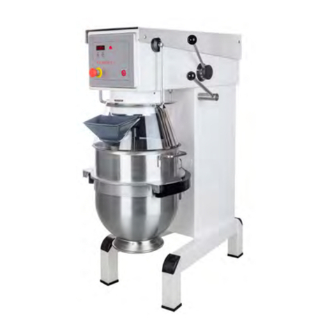
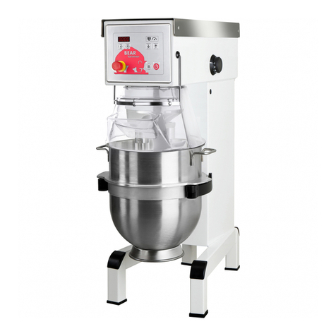
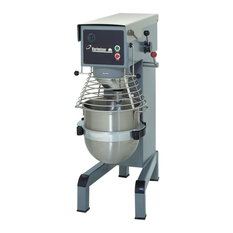
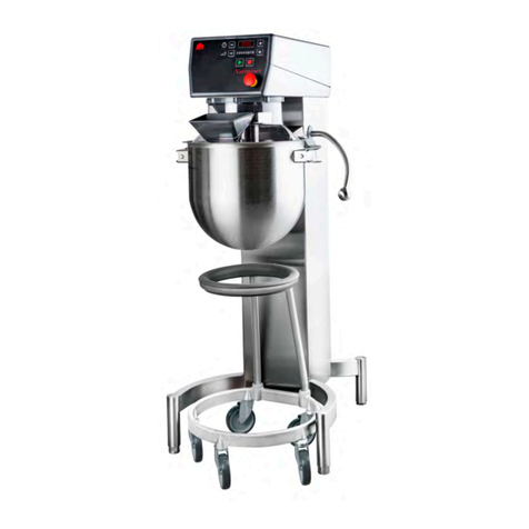
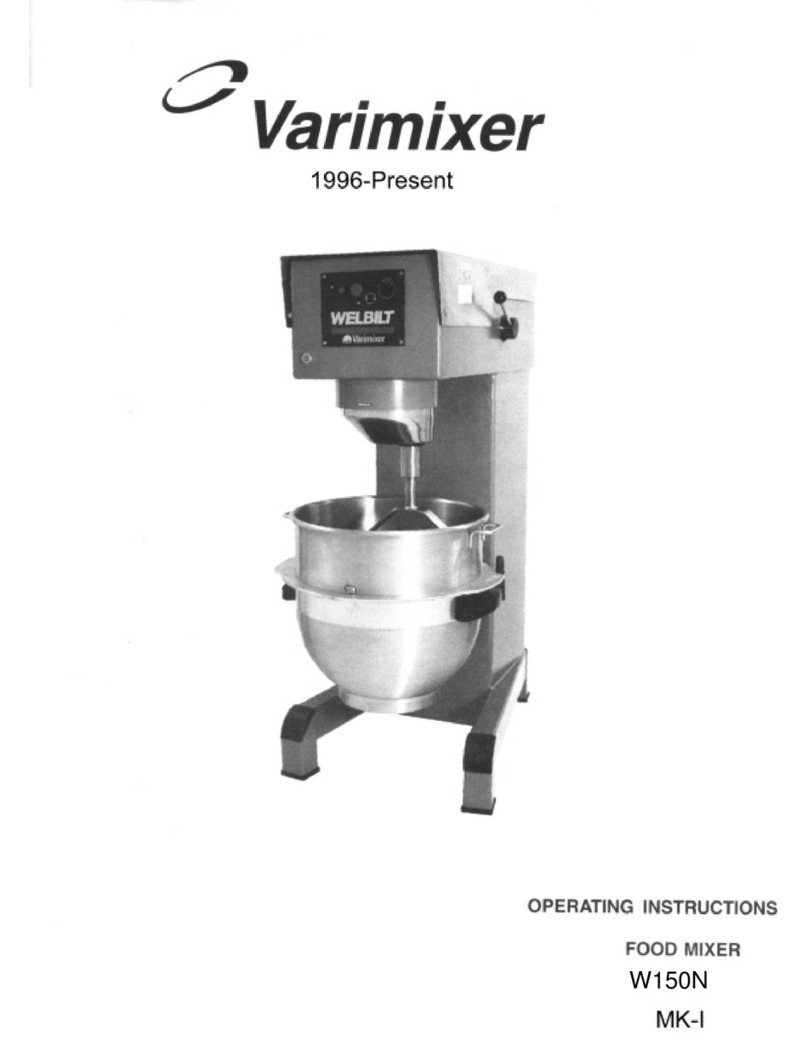
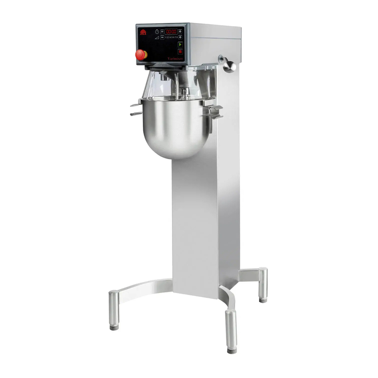
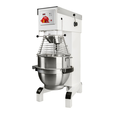
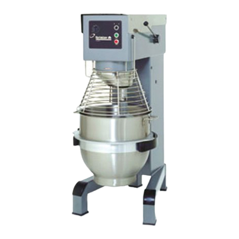
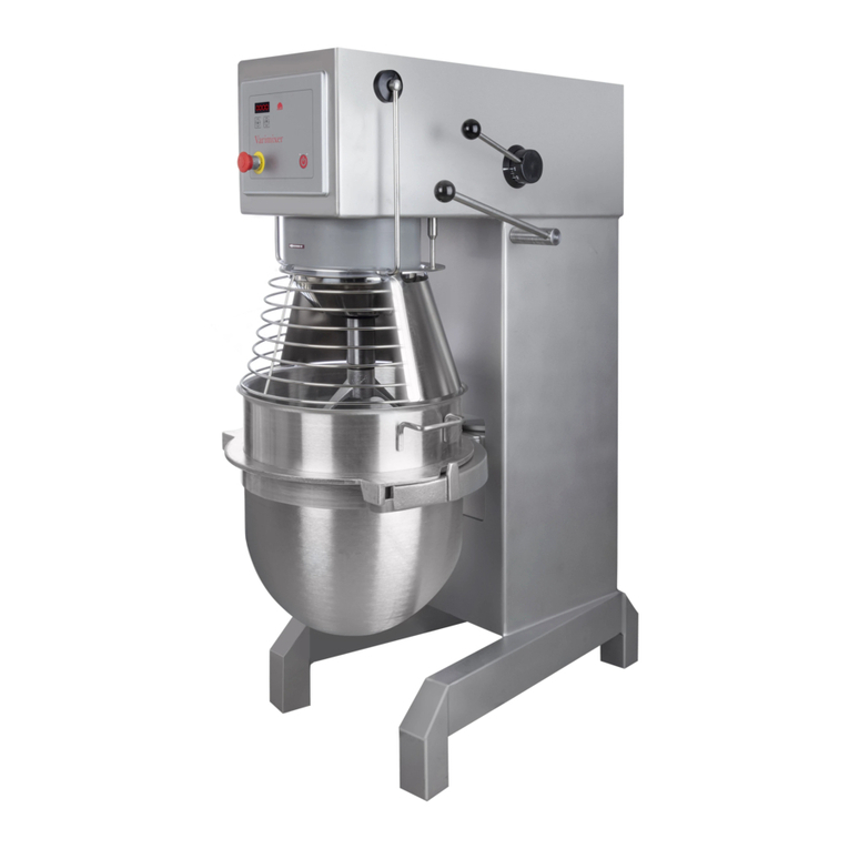
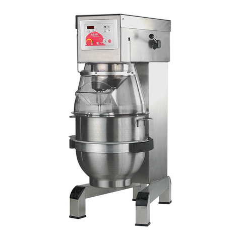
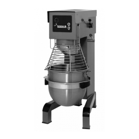
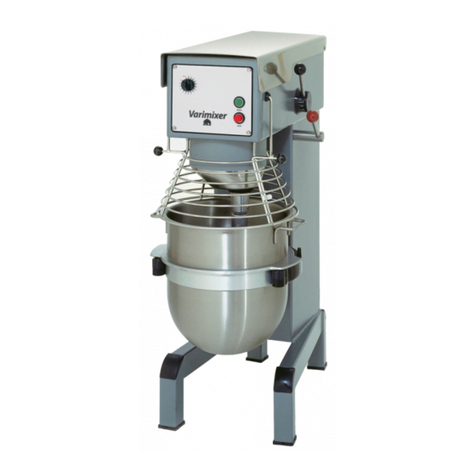
Varimixer V150PLM User manual

V
V150PLM
EN
Operating Instructions
DRN: 20150-0436
Original user manual
2022 01 17
Varimixer USA
2215 East River Road
Moraine, Ohio 45439
P: (800) 222-1138
varimixerusa.com

2
Limited Mixer Warranty - 10 qt to 150 qt
VARIMIXER warrants to the original purchaser of new equipment that said equipment, when installed in accordance
with our instructions within North America and subjected to normal use, is free from defects in material or workmanship
for a period of 4 years. Wear parts, such as belts, are excluded. Hub attachments, such as shredders, slicers and
grinders have a 1 year warranty that only covers parts. Warranty begins on date of factory shipment to an end user, or
up to 6 months after factory shipment to a dealer or distributor. Payment by VARIMIXER for service under this warranty
requires that service be authorized in advance. Contact VARIMIXER Technical Support to arrange for service.
THIS WARRANTY IS IN LIEU OF ALL OTHER WARRANTIES, WHETHER EXPRESSED OR IMPLIED. VARIMIXER
EXPRESSLY DISCLAIMS ANY IMPLIED WARRANTY OF MERCHANTABILITY OR EXPRESSED OR IMPLIED
WARRANTY OF FITNESS FOR A PARTICULAR PURPOSE.
VARIMIXER’S OBLIGATION AND LIABILITY UNDER THIS WARRANTY IS EXPRESSLY LIMITED TO REPAIRING
AND REPLACING EQUIPMENT WHICH PROVES TO BE DEFECTIVE IN MATERIAL OR WORKMANSHIP WITHIN
THE APPLICABLE WARRANTY PERIOD. All repairs pursuant to this Warranty will be performed by an Authorized
Designated VARIMIXER Service Location during normal working hours. IN NO EVENT SHALL VARIMIXER BE
LIABLE FOR INCIDENTAL OR CONSEQUENTIAL DAMAGES TO BUYER OR ANY THIRD PARTY, INCLUDING,
WITHOUT LIMITATION, LOSS OF PROPERTY, PERSONAL INJURY, LOSS OF BUSINESS OR PROFITS OR OTHER
ECONOMIC LOSSES, OR STATUTORY OR EXEMPLARY DAMAGES, WHETHER IN NEGLIGENCE, WARRANTY,
STRICT LIABILITY, OR OTHERWISE.
This warranty is given only to the rst purchaser from a retail dealer. No warranty is given to subsequent transferees.
This warranty does not cover product failures caused by: failure to maintain, neglect, abuse, damage due to excess
water, re, normal wear, improper set up and use. Periodic maintenance is not covered.
Example of items not covered under warranty, but not limited to just these items:
1. Acts of God, re, water damage, vandalism, accident, theft.
2. Freight damage.
3. Improper installation or alteration of equipment.
4. Use of generic or after market parts.
5. Repairs made by anyone other than a VARIMIXER designated servicer.
6. Lubrication.
7. Expendable wear parts. (This includes the bowl, at beater, wire whip, spiral dough hook,
and the pastry knife.)
8. Cleaning of equipment.
9. Misuse or abuse.
This warranty is not in force until such time as a properly completed, digitally signed Installation/Warranty Registration
has been received by VARIMIXER within 30 days from the date of installation.
Register online at www.varimixerusa.com/support/warranty-registration-form.
THE FOREGOING WARRANTY PROVISIONS ARE A COMPLETE AND EXCLUSIVE STATEMENT BETWEEN THE
BUYER AND SELLER. VARIMIXER NEITHER ASSUMES NOR AUTHORIZES ANY PERSONS TO ASSUME FOR IT
ANY OTHER OBLIGATION OR LIABILITY IN CONNECTION WITH SAID EQUIPMENT.
WARRANTY REGISTRATION
GO TO VARIMIXERUSA.COM
TO FILL OUT AND SUBMIT YOUR WARRANTY REGISTRATION.
VARIMIXERUSA.COM/SUPPORT/WARRANTY-REGISTRATION-FORM
3
Caution -READ BEFORE OPERATING- Caution
Varimixer recommends that mixer operators must be at least 18 years of age and be thoroughly
trained on the use, cleaning and lubrication of the mixer.
This manual should be seen as an integral part of the mixer and should be kept by the machine
throughout its working life.
Before the machine is commissioned, it is important to read these instructions thoroughly.
The manufacturer may update the product manual without updating this copy of the manual.
Varimixer recommends that the following precautions be adopted to help make the mixer operation
safer and more efficient.
- All operators must be at least 18 years of age.
- All operators must be thoroughly trained before being allowed to operate the mixer.
- NEVER reach into the bowl when the mixer is running.
- Do not wear loose clothing or rings while operating the mixer.
- Stop the mixer and lower the bowl before adding ingredients, scraping the bowl, removing
the agitator, or removing the product.
- Stop the mixer before removing or installing attachments into the drive hub.
- Do not attempt to assemble or disassemble attachments while mounted into the drive hub.
- Always use the pusher plate with the slicer/meat grinder attachments.
- NEVER bypass the safety mechanisms supplied on the mixer. Doing so can cause injury
and is the responsibility of the user to ensure these safety mechanisms are operating prop-
erly.

4
TABLE OF CONTENTS
Installation Instructions.................................................................................................5
Operating Instructions ..................................................................................................6
Cleaning .......................................................................................................................7
Maintenance - Lubrication............................................................................................8
Belt Adjustments and Removal.....................................................................................7
Construction of the mixer .............................................................................................9
Capacity Chart..............................................................................................................9
Adjustment of V-belt and speed .................................................................................10
Adjusting the Bowl Clamping and centering ..............................................................11
Spare parts
Machine Column .................................................................................................. 14-15
Bowl Arms ............................................................................................................ 16-17
Microswitches....................................................................................................... 18-19
Planetary Head..................................................................................................... 20-21
Transmission ........................................................................................................ 22-23
Speed Lever Assembly......................................................................................... 24-25
Instrument Panel .................................................................................................. 26-27
Power Supply ....................................................................................................... 28-29
Bowl Screen ......................................................................................................... 30-31
Accessories .......................................................................................................... 32-33
Electrical Diagrams .............................................................................................. 34-35

5
1. Lower the bowl using the bowl
lift switch on the front panel.
4. Close bowl screen and raise
the bowl arms into the up
position.
5. Turn timer to 10 minutes and
push “start” .
6. Insure cover is rotating in
the correct direction.
2. Open the bowl screen. 3. Remove the bowl
and tools.
Bowl Lift
Start
Stop
Timer
JOG
button
Bowl Lift
Start
Stop
Timer
JOG
button
Wire Color Codes
White-Phase 1
Red -Phase 2
Black-Phase 3
Green-Ground
No Neutral is used
Read this page entirely BEFORE beginning installation.
INSTALLATION INSTRUCTIONS
UNDER NO CIRCUMSTANCES ARE THE SPEED LEVER, BOWL LIFT LEVER, OR THE BOWL
ARMS TO BE USED TO MOVE THE MIXER INTO PLACE. DAMAGE WILL RESULT TO THE UNIT.
IT IS RECOMMENDED THAT THE TOP LID BE REMOVED BEFORE MOVING THE UNIT.
The mixer must be mounted with the rubber feet, which neutralize both shaking and rusting.
Spacers can be inserted under the mixer’s feet if the floor is uneven. The mixer can be bolted to the
floor if desired.
Before the mixer is connected to power, it should be checked that the voltage and frequency on the
rating plate is correct in relation to the place of installation. The rating plate is located on the rear
right side of the mixer. The electrical connection box is located at the top rear of the mixer.
WARNING
Electrical and grounding connections must comply with applicable portions of the National Electrical
Code and/or other local electrical codes.

6
A) Place the tool in the bowl. Open the bowl screen
B) Note: the bowl arms must be in the lowest position.
Place the bowl in the bowl arms. Check that the bowl
is pushed right back into the arms and that the “Third
ear” of the bowl is facing the mixer (g. 3). Place the
mixer tool in the bayonet shaft. The tap of the tool must
be turned right into the bayonet hole. Close the bowl
screen.
C) The bowl is raised to working position by a clockwise
turn of the button for bowl lift - the JOG-button must be
pushed and kept pushed until the bowl is entirely up.
Ensure that the bowl is placed correctly. On the timer
set the mixing time required by turning the timer (g
1) clockwise. The mixer will stop automatically, when
the time runs out. When the mixer has timed out, the
"procedure for starting after emergency stop" is used
before the mixer is re-started.
D) Start the mixer by pressing the green start button
(fig.1)
The mixer will only start when the bowl is in the "up"
position, the bowl screen is "closed", and the timer is
set to "time" or "hold".
E) Turn the speed selector lever (fig. 4) to the rear until
the required speed has been obtained, (notice the
recommended maximum speeds on page 7).
F) Before the mixer is stopped, the speed selector lever
must be moved back to lowest speed (fig.4).
G) Stop the mixer by pressing the red stop button (fig.1)
1) This procedure must be used in cases where the mixer
has been interrupted in high speed.
2) Lower the bowl and remove the tool from the bayonet.
3) Close the bowl screen.
Raise the bowl arms, either empty or with the bowl.
4) Start the mixer and move the speed selector lever
back to lowest speed. Switch off the mixer. Now the
mixer can be started as usual.
JOG”- function:
The mixer is provided with a “JOG” button located
underneath the operating panel. The button must be
activated simultaneously with key for bowl lift when the
bowl is lifted
Before the bowl reaches its top position, the tool starts
rotating to dig its way into the ingredients.
First “ear”
Fig. 3
Mixer seen from above, the
bowl has been pushed all
the way into the bowl arms.
mixer
Fig. 4
Fig. 1
Fig. 2
“ear”
Bowl Lift
Start
Stop
Timer
JOG
button

7
Do not overload the mixer. Sticky and heavy
doughs can overload the mixer. Overloading is fur-
ther exacerbated if the speed of the mixing tool is
increased beyond the recommended values or if a
wrong mixing tool is used. Large lumps of fat or cooled
ingredients must be cut into small parts before they
are placed in the bowl.
Whips should not be struck against hard objects
as e.g. the edge of the bowl. This will make the life of
the tool shorter due to increasing deformity.
For production of mashed potatoes the special
wing whip or the reinforced whip should be used, alter-
natively use the beater and the whip.
NOTE: Speed should never exceed 150 RPM when
using the dough hook. Our dough hook is designed to
give you optimum product on low speed.
Beater Hook
Cream Cake dough Bread dough
Egg whites Butter cream Dark bread
Mayonnaise Wae dough and the like
and the like Minced meat
and the like
The mixer should be unplugged before cleaning
to prevent accidental starting while cleaning.
The mixer should be cleaned daily or after use.
The mixer should be cleaned with a soft cloth and
clean water. Sulphonated soaps should be used with
caution as they destroy the mixer’s lubricants.
Never use high pressure cleaning for the mixer.
Parts made of aluminium should not be used to strong-
ly acidic, highly alkaline or highly salty foodstus,
which may attack aluminium without coating.
Tools of aluminium must not be washed with strong
alkaline detergents
(pH between 5 and 8).
The soap suppliers can recommend the correct type of
soap.
The inside of the bayonet shaft should be cleaned
once a day with warm, soapy water.
Dough hook Cleaning: Special care should be
given to cleaning the dough hook. We recommend that
it be cleaned and sanitized in a commercial dish ma-
chine. An alternate cleaning procedure is to vigorously
scrub the hook with a hot water and detergent solution.
Use a heavy bristled brush. After cleaning, sanitize
the hook by rinsing it with a 50 ppm solution of sodium
hypochlorite.

8
Fig.5
The innitely variable gear must be lubricated regularly, i.e. a lubrication interval of approx. 60 hours of operation.
OBS. Special grease !!(Use the grease gun delivered together with the mixer). Start the mixer and increase the speed
to approx. 50%. Stop the mixer and disconnect the power cable. Open the lid on the top of the mixer. On the top of each
of the two pulley set shafts is a grease nipple . Press grease through the grease nipple until the grease gun feels
hard to press or until grease comes out between the shaft and the pulleys.
The mixer must not be started until the lid is closed and the screws which hold the lid are inserted.
Start the mixer, and set the speed back to low speed.
Stop the mixer and ll the grease gun with new grease so that it is ready for next time.
The movable parts of the bowl arms as well as the shaft must be lubricated with oil.
Disconnect the power cable. Remove the rear covering and lubricate the marked points with an oil can.
Pulley set shafts: TOTAL MULTIS XHV 2.
Planetary head: Only to be repaired by an authorised technician.
Toothed wheel and the toothed rim special grease
Needle bearings Special grease
Do not use any another type of grease than the one stated here.
Fig.5a

9
Motor
screen Fuse
V150PL
Dough, Bread 65%AR 190 lbs
Dough, Pizza 50% AR 175 lbs
Dough, Donut-Yeast 170 lbs
Dough, Donut-Cake 225 lbs
Pie Dough 135 lbs
Cookie, Dough 160 lbs
Muns 195 lbs
Mashed Potatoes 110 lbs
Pancakes, Waes 50 qt
Whipped Cream 32 qt
Cake, Layer 175 lbs
Eggs & Sugar 80 lbs
Icing , Fondant 105 lbs
Egg Whites 4 qt
Cake, Cup 250 dz.
Cookies, Sugar 240 dz.
(Liquid in % of solids)
1 Gallon =8.33 lbs.
1 Quart =2.08 lbs.
1 Pint (16 oz.) =1.04 lbs.
1 Cup = .52 lbs.
Batch size and/or speed reduction may be necessary due to one
of the following conditions:
1. High Gluten Flour-Reduce batch size by 10%
2. AR % under 40%-Reduce batch size by 10%
3. Water temp under 65 Degrees F
4. USE OF ICE REQUIRES A 10% REDUCTION IN BATCH
SIZE.
5. Speed should not exceed 100 RPM when mixing dough.
V150
5 Hp
„JOG“ function

10
A rattling sound from the closed part of the mixer. Adjustment of special V-belt
The mixer starts “striking” when kneading dough Adjustment of special V-belt
which normally causes no problems.
The mixer changes its speed by itself. Adjustment of special V-belt
The minimum and the maximum speeds are changing. Adjustment of speed.
The bowl is too tight or too loose. Adjustment of bowl xing
The tool hits the sides of the bowl. Adjustment of bowl centering
The tool hits the bottom of the bowl. Adjustment of bowl height
The distance is only indicative as it depends on the
tolerance of the special V-belt.
1. Start by tightening the V-belts (*
2. Tighten the special V-belt by moving one or two
washers from to .
3. Start the mixer and leave it running while the nut
is tightened. Do not tighten it too much.
4. On the front pulley set the stud on the varispeed
collar must be placed inside the lower fork
and on the rear pulley set outside the fork for belt
tightener , (both must point backwards).
5. Tolerances in the transmission might cause that the
special V-belt is hitting the pins of the pulley
sets when the speed has been adjusted. In such
cases the distance must be reduced. (+ or -
1/8" of 12 1/4")
6. Then follow the section:
1. The stop screws on the speed lever should be
adjusted so that the measurement is
on the front and the rear pulley, at low and high
speed, respectively. Tighten the counter nuts
when the speed is correctly adjusted.
2. Tolerances in the transmission might cause that the
special V-belt is hitting the pins of the pulley
sets when the speed has been adjusted In such
cases the distance must be reduced, see
, and the speed must be
readjusted.

11
In the rear part of the bowl arms a shaft with an eccentric stud has been mounted, on which the ball bearing is
mounted. By turning the eccentric stud, the bowl arms can be opened and closed so that the clamping and the center-
ing of the bowl can be adjusted. It has to be observed that the shaft is mounted in the bowl arm with a thread so that
when the eccentric stud is turned, the whole shaft is turned out and in into the bowl arms. When exchanging the whole
shaft, the right starting point for the adjustment must be found rst. The ball bearing must be in the middle of the
guide plate (M) so that the width of the entire ball bearing is tting tightly against the guide plate, and at the same time
it has to be observed that the eccentric stud cannot hit the back plate when the adjustment has been nished.
In order to counteract that the eccentric shaft turns loose by itself when the mixer is working, the eccentric shaft must
be self-tightening. In order to obtain this eect, the below drawings must be followed, on which the adjusting area for
the left and the right bowl arm, resp. is shown.
First nd the bowl centering, e.g. by mounting bowl and beater in the mixer, and turn the beater round with your hand,
and measure the distance from the beater to the edge of the bowl.
• When adjusting the clamping and centering of the bowl,
the bowl arms must be raised into working position. When
exchanging the shaft with eccentric stud (K) the bowl arms
must be lowered.
• First open the lock plate (N).
• Loosen the shaft counter nut (P), use span 46.
• Screw an M8 bolt with counter nut (R) into both the ec-
centric studs (K), and tighten the counter nuts. If the shaft
with the eccentric stud has stuck in the bowl arm, it can be
loosened with a key with the span 36.
• By turning the eccentric studs the clamping and the center-
ing of the bowl can be adjusted.
• Remember to use the right adjusting area for right and left
bowl arm. The drawings show the adjusting area for
• When the adjustment is correct, tighten the shaft counter
nuts (P). Hold the bolt (R) while the shaft counter nut is
tightened.
• Knock the lock plate (N) in position.
• Remove bolt and counter nut
Movement of the
bowl arm
Tight bowl
clamping
Tight bowl clamping
Movement of the
bowl arm
Loose bowl clamping
Adjusting diameter
Loose bowl
clamping

12
This page intentionally left blank

13
ORDERING OF
Sales of spare parts for our mixers, are
handled in our sales and service depart-
ment. When ordering spare parts, the
following information must be provided:
If one of the above pieces of informa-
tion is missing, please contact our sales
and service department before placing
the order, as then we can assist you in
nding the correct article number
of the spare part in question.
A few spare parts are not sold alone, in
such cases reference is made at the pos.
number to the assembly number to be
used for ordering. The assembly num-
bers are shown on the relevant pages.
Returning of spare parts is only
allowed when agreed with:
Varimixer

14
Varimixe r
BEAR
A/SWo dschow&C o.
Industrisving et6
P.OBo x 110
DK-2605Brøndby
Phone:+4543442288
C E
MachineTy pe
Machine No.
2
3
4
5
6
7
8
14
15
16
17
10
11
12
9
13
1
18
19
20

15
Description
1. Column
2. Top Lid AR140-21.3R1
3. Rear Access Panel AR140-22.17R1
4. Threaded Bushing Top Lid STA6580
5. Screw Top Lid STA5017
6. Screw Rear Access Plate STA5080
7. Indicator Arrow R15-245
8. Plug Button (non bowl screen only) STA6519
9. Knee Pad AR80-212
10. Levelling feet AR80-213
11. Adjustment plate, 0.12” AR80-214.3
12. Adjustment plate, 0.24” AR80-214.6
13. Bushings Bowl Arm Shaft STA2530
14. Upper Plate AR140-270
15. Lower Plate AR140-274
16. Nut for Plate STA5834
17. Washer STA6027
18. Grid AR140-22.180
19. Screw grid STA5045
20. Tie rod for motor bracket AR140-148M4
Fig.No.

16

17
Description
1.
1C.
2.
3.
4.
5.
6.
7.
8.
9.
10.
11.
12.
13.
14.
15.
16.
17.
18.
19.
20.
21.
22.
23.
24.
25.
26.
27.
28.
29.
30.
31.
32.
33.
34.
35.
36.
37.
Bowl Lift Moto
Control Box for 24VDC (Not shown)
Bracket Lower Bowl Lift Motor
Bolt
Pin for lower bowl lift motor
Cotter pin
Washer
Pneumatic Spring
Bracket f/Pneumatic Spring
Upper Bolt f/Pneumatic Spring
Bolt
Nut
Lock washer
Bowl Arms
Bowl Arm Roller Threaded Shaft
Bowl Arm Front Roller
Tapered Roller for Bowl Arms
Bushing for Tapered Roller
Bowl arm bushing
Bowl arm bushing
Screw Bowl Arm Roller
Socket Head for Roller
Washer
Plug Button Bowl Arm Bolt
Nut
Bolt
Bowl Arm Shaft
Snap Ring
Bowl Arm guide plate
Screw for guide plate
Sold with assembly AR140-69M only
Snap Ring
Nut Bowl Arm Adjuster
Lock Plate / Bowl Arm Adjuster
Washer
Ball Mounting, Pneumatic Spring
Fastening Ball, Pneumatic Spring
AR140-86.1
140-87
AR140-116
STA5454
RN100-8635
STA6205
STA6058
AR140-121
AR140-119
AR140-120
STA5454
STA5815
STA6058
AR140-23/24M2
AR31-127
AR31-128
AR140-127
AR140-128
STA2527
STA2530
STA5088
STA5678
STA6010
STA6518
STA5825
STA5345
AR140-68Z
STA3464
AR140-71.1M4
STA5620
see diagram
see diagram
STA3467
AR140-170
AR140-69.1
STA6020
AR140-121.1
AR140-121.2
Fig.No.

18
4
5
2
1
1
1
2
2
3
3
7
AR140-63M
6
7
8
9

19
Description
1.
2.
3.
4.
5.
6.
7.
8.
9.
Bowl Arm Microswitch
Cable Inlet
Microswitch Mounting Screws
Bolt Bowl Lift Bracket
Lock washer
Micro stand
Fitting for Micro stand
Microswitch UR
Screw
AR81-173
STA3076
STA5274
STA5312
STA6053
AR140-63
AR140-64
AR81-173
STA5274
Fig.No.

20
.........
..............
................
................
..........
..............
............
Fig.No
1.
2.
3.
4.
5.
6.
7.
8.
9.
10.
11.
12.
13.
14.
15.
16.
17.
18.
19.
20.
21.
22.
23.
24.
25.
26.
27.
28.
29.
30.
31.
32.
33.
34.
35.
36.
37.
38.
39.
41.
42.
43.
44.
46.
47
Description V150PL
Ball Bearing ..............................................................R100-98
Snap Ring................................................................. STA3532
Bolt ...........................................................................STA5346
Lockwasher ..............................................................STA6057
Main Bearing Casting ...............................................R100-32
Distance Tube...........................................................R100-141
Gear Wheel ..............................................................R100-1
Screw........................................................................STA5044
Cap...........................................................................AR80-162H
Spacer ......................................................................R100-37
Snap Ring................................................................. STA3530
Snap Ring................................................................. STA3478
Eccentric Disc........................................................... R100-36
Ball Bearing ..............................................................R100-100
Snap Ring................................................................. STA3530
Needle Bearing w/ Race........................................... R100-96
Washer .....................................................................R100-235
Key ...........................................................................STA2030
Upper Rim Pinion .....................................................R100-31
Main Shaft ................................................................R100-30
Lower Rim Pinion .....................................................AR140-32
Pin ............................................................................STA6460
Lower Planetary Head Casting................................. R100-2
Lock washer .............................................................STA6057
Bolt ...........................................................................STA5644
Seal ..........................................................................R100-108R
Needle Bearing w/Race............................................ R100-101
Spacer ......................................................................R100-37
Ball Bearing ..............................................................R100-97
Snap Ring................................................................. STA3532
Key ...........................................................................STA2034
Key ...........................................................................STA2039
Stainless Steel Cover ...............................................W100-272
Rubber Ring .............................................................R150-209
Lock washer .............................................................STA6029
Bolt (Allen Head-under cover) ..................................STA5652
Bayonet Shaft...........................................................AR140-33
Screw........................................................................STA5632
Ball Bearing ..............................................................R100-99
Disk...........................................................................STA6048
Planetary pulley........................................................RN100-129A
Snap ring ..................................................................STA3419
V-Belt (Must be changed as a set) ...........................RN100-90.2
Bayonet Shaft...........................................................AR140-33.5Z
Fig.No
38.
.....
.........
Table of contents
Other Varimixer Mixer manuals

Varimixer
Varimixer AR Series User manual

Varimixer
Varimixer AR100 VL-1L User manual

Varimixer
Varimixer ERGO60 User manual

Varimixer
Varimixer V30K Guide

Varimixer
Varimixer V150PL Guide

Varimixer
Varimixer V30K Guide

Varimixer
Varimixer V80 User manual

Varimixer
Varimixer RN Series User manual

Varimixer
Varimixer KODIAK V20KT Guide

Varimixer
Varimixer KODIAK20 User manual

Varimixer
Varimixer W30 User manual

Varimixer
Varimixer V30 User manual

Varimixer
Varimixer W80 Guide

Varimixer
Varimixer W20 F Guide

Varimixer
Varimixer V20K Guide

Varimixer
Varimixer V20 User manual

Varimixer
Varimixer W20A Guide

Varimixer
Varimixer W20P User manual

Varimixer
Varimixer W100PL User manual

Varimixer
Varimixer KODIAK10 User manual