VeEX VePAL MX120e+ User manual

MX100e+/MX120e+ e_Manual D07-00-050P RevD00
Page 1 of 115

Table of Contents
1.0 About this User Manual
2.0 Introduction to MX100e+ and MX120e+
2.1 MX100e+ Introduction
2.2 MX120e+ Introduction
3.0 Safety Information
4.0 Basic Operation
4.1 Keypad
4.2 Touch Screen Display
4.3 Battery
4.4 Connectors and Panels
4.4.1 Test Ports
4.4.2 Utility Ports
4.5 LEDs
4.6 Software Upgrade
5.0 Home Menus
5.1 Screen Layout
5.2 Screen Icons
5.3 Action Menu
6.0 Setup
6.1 Port Setup
6.2 Port Status
6.3 Laser Activation
6.4 Profiles
6.5 Measurement Settings
7.0 BERT
7.1 BERT Setup
7.1.1 Header Settings
MX100e+/MX120e+ e_Manual D07-00-050P RevD00
Page 2 of 115

7.1.2 Traffic Settings
7.1.3 Error Injection Settings
7.1.4 Control Settings
7.1.5 Starting/Stopping a BERT Test
7.2 BERT Results
7.2.1 Summary
7.2.2 Errors
7.2.3 Events
7.2.4 Alarms
7.2.5 Traffic
7.2.6 Rates
7.2.7 Delay
7.2.8 Saving BERT Results
8.0 RFC 2544 Conformance Testing
8.1 RFC 2544 Setup
8.1.1 Header Settings
8.1.2 Frame Settings
8.1.3 Threshold Settings
8.1.4 Throughput, Latency, Frame Loss, and Burst Settings
8.1.5 Control Settings
8.1.6 Starting/Stopping an RFC 2544 Test
8.2 RFC 2544 Results
8.2.1 Status and Events
8.2.2 Throughput
8.2.3 Latency
8.2.4 Frame Loss
8.2.5 Burstability
8.2.6 Saving RFC Results
9.0 Throughput Testing (Multiple Streams)
MX100e+/MX120e+ e_Manual D07-00-050P RevD00
Page 3 of 115

9.1 Setup
9.1.1 General Settings
9.1.2 Control Settings
9.1.3 Header Configurations (Individual Streams)
9.1.4 Traffic Settings (Individual Streams)
9.1.5 Error Injection Settings (Individual Streams)
9.1.6 Starting/Stopping a Throughput Test
9.2 Throughput Results
9.2.1 Viewing Test Results (Individual and Multiple Streams)
9.2.2 Global Results (Multiple Streams)
9.2.3 Individual Stream Results
9.2.4 Saving Throughput Results
10.0 OAM Testing
10.1 OAM Setup
10.1.1 Link Level 802.3ah OAM Setup
10.1.2 Service Level OAM
10.2 OAM Results
10.2.1 Link OAM Results
10.2.2 OAM Service Results
10.3 Definitions
10.3.1 802.3ah OAM Discovery
10.3.2 IEEE 802.1ag Definitions
10.3.3 Measurement Definitions
11.0 Monitor Mode - Pass Through (MX120e+ only)
11.1 Setup
11.2 Results
11.2.1 Errors
11.2.2 Alarms
11.2.3 Events and Status
MX100e+/MX120e+ e_Manual D07-00-050P RevD00
Page 4 of 115

11.2.4 Traffic Distribution Details
11.2.5 Delay and Rates
11.2.6 Port Selection
12.0 Loopback
13.0 V-SAM
13.1 V-SAM Overview
13.2 V-SAM Setup
13.2.1 General Settings
13.2.2 Services - Header
13.2.3 Services - Bandwidth
13.2.4 Services - Thresholds
13.2.5 Control Settings
13.3 Results
13.3.1 Configuration Results
13.3.2 Performance Results
14.0 Additional Tests
14.1 Packet Capture
14.2 Scan
14.3 NetWiz
14.4 Profile Scripting (MX100e+ only)
15.0 Common Functions
15.1 IP
15.2 Net Wiz
15.3 Settings
15.4 Files
15.5 Help
15.6 Backlight
15.7 Tools
16.0 ReVeal MTX Software
MX100e+/MX120e+ e_Manual D07-00-050P RevD00
Page 5 of 115

16.1 Profiles
16.2 Results
16.3 Software
16.4 Tools
16.4.1 Remote Control
17.0 Warranty and Software
18.0 Product Specifications
19.0 Certification and Declarations
20.0 About VeEX
Go back to ToC
1.0 About This User Manual
Every effort was made to ensure that the information contained in this user manual is accurate. Information is subject to change
without notice and we accept no responsibility for any errors or omissions. In case of discrepancy, the web version takes
precedence over any printed literature.
(c) Copyright 2006-2013 VeEX Inc. All rights reserved. VeEX, VePAL are registered trademarks of VeEX Inc and/or its affiliates in
the USA and certain other countries. All trademarks or registered trademarks are the property of their respective companies. No
part of this document may be reproduced or transmitted electronically or otherwise without written permission from VeEX Inc.
This device uses software either developed by VeEX Inc or licensed by VeEX Inc from third parties and is the confidential and
proprietary of VeEX Inc. The software is protected by copyright and contains trade secrets of VeEX Inc or VeEX's licensors. The
purchaser of this device agrees that it has received a license solely to use the software as embedded in the device, and the
purchaser is prohibited from copying, reverse engineering, decompiling, or disassembling the software.
This user manual is suitable for novice, intermediate, and experienced users and is intended to help you successfully use the
features and capabilities of the VePAL MX100e+/MX120e+ test set. It is assumed that you have basic computer experience and
skills, and are familiar with IP and telecommunication concepts, terminology, and safety.
For more technical resources, visit VeEX Inc web site at www.veexinc.com.
If you need assistance or have questions related to the use of this product, call or e-mail our customer care department for
customer support. Before contacting our customer care department, you must have your product serial number and software
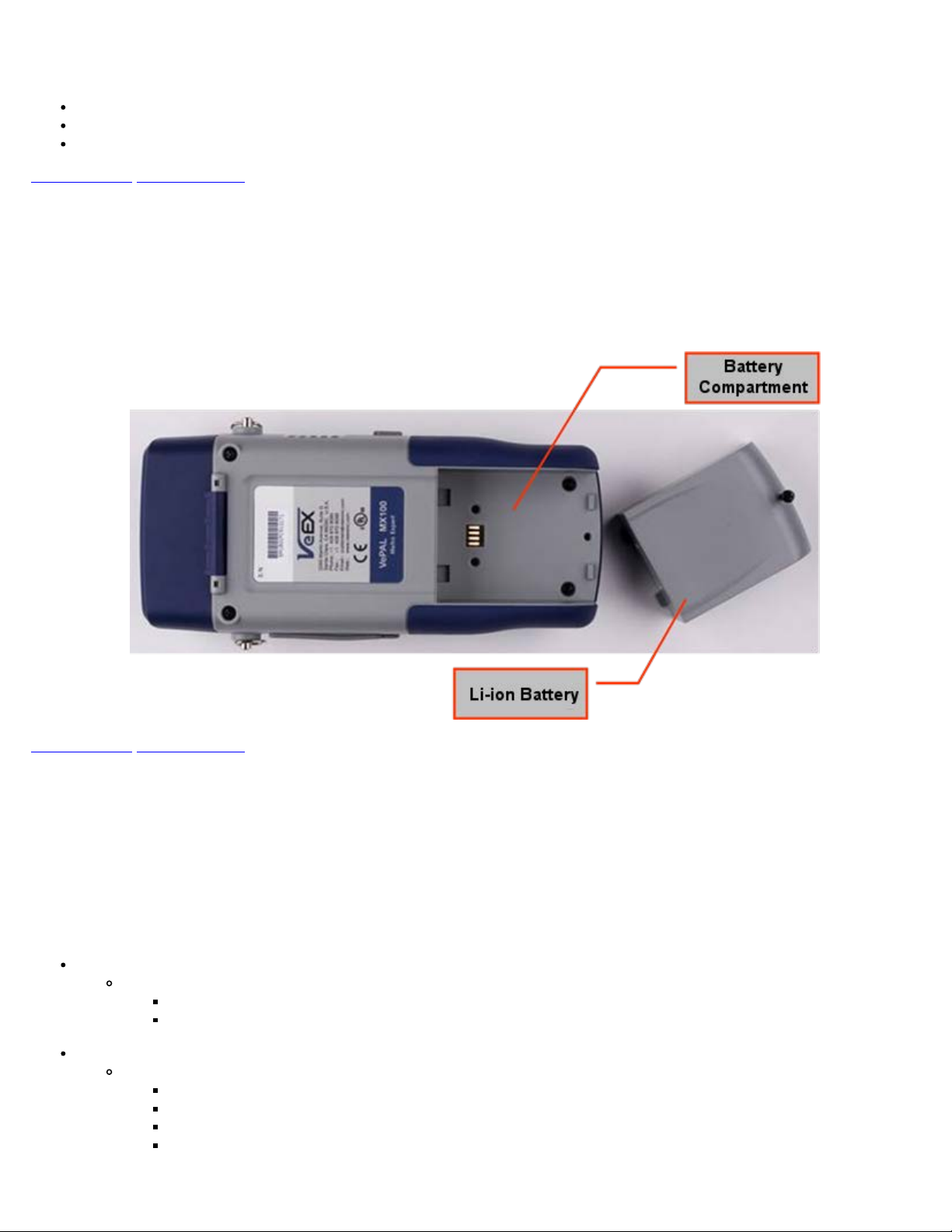
version ready. Please go to the Basic Operations section for details on locating your unit serial number in the menus or locate the
serial number on the back of the chassis. Please provide this number when contacting VeEX customer service.
Customer Care:
Phone: + 1 510 651 0500
E-mail: [email protected]
Website: www.veexinc.com
Go back to top Go back to ToC
2.0 Introduction to MX100e+ and MX120e+
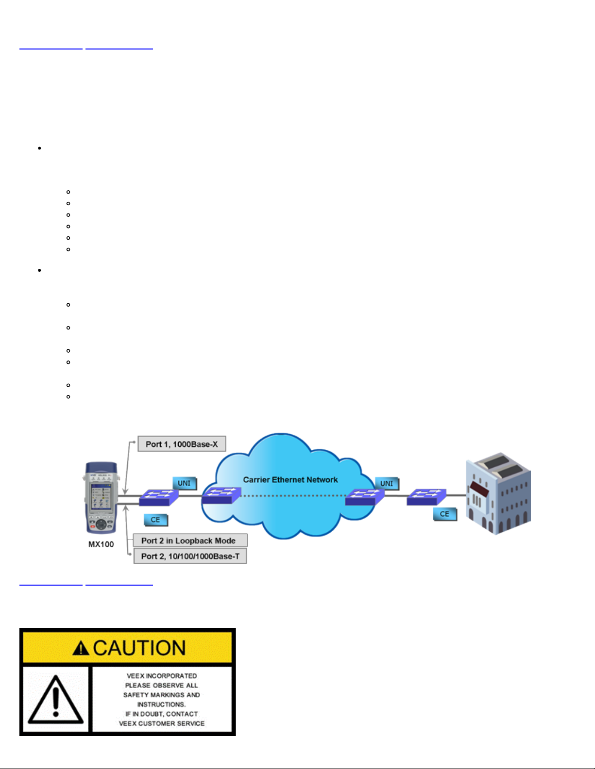
VeEX™ MX100e+ and MX120e+ Metro Expert test sets are the next generation of Metro and Carrier Ethernet field test equipment
for Ethernet Networks. The units are lightweight, rugged and weather resistant, and feature Gigabit Ethernet and Fast Ethernet test
ports complete with advanced Triple Play verification capabilities. The test sets can be used in conjunction with the MPX100
MX100e+/MX120e+ e_Manual D07-00-050P RevD00
Page 6 of 115

loopback device offering simplified network testing and monitoring. The MX100e+ shares all the same features as the MX100+
unit, with the additional support of 100Mbps optical on SFP. Note that any reference in this manual to MX100e+ applies to the
MX100+ product and any reference to MX120e+ applies to MX120+ product, respectively.
Go back to top Go back to ToC
2.1 MX100e+ Introduction
The MX100e+ is part of the MX product family and is configured for:
Single Port Operation
Single Copper port 10/100/1000Base-T
Single Fiber port 100FX/1000Base-X
Test Applications (when the unit is operating in any of the physical ports above)
BERT: Unframed / Framed Layer 1, and Framed Layer 2/3 Ethernet traffic generation with user selectable test
pattern for Bit Error Rate analysis.
RFC 2544: Throughput, Back-to-Back, Frame Loss and Latency conformance tests in accordance with RFC 2544
specifications.
Throughput: Ethernet traffic generation and analysis with multiple streams to verify network throughput and jitter.
Loopback: Loop back the transmitted data while swapping the source and destination addresses of the MAC, IP and
UDP layers.
V-SAM test suite in conformance to ITU-T Y.1564 standard.
MX100e+ - End-to-End Performance Test Application
MX100e+/MX120e+ e_Manual D07-00-050P RevD00
Page 7 of 115

Go back to top Go back to ToC
2.2 MX120e+ Introduction
The MX120e+ is part of the MX product family - in essence the MX120e+ is similar to having two MX100e+ units in one chassis.
The default configuration of the MX120e+ allows for single port operation (same as the MX100e+), dual port operation, and pass
through monitor mode. Pass through monitor mode enables bidirectional monitoring between the two 100Base-FX/1000Base-X
ports or the two 10/100/1000Base-T ports.
Dual Port Operation
When the dual port interfaces and software options are enabled, the test set can operate a combination of two ports at the
same time with the following physical port operation combinations:
Port 1 10/100/1000Base-T and Port 2 10/100/1000Base-T (copper ports only)
Port 1 100Base-FX/1000Base-X and Port 2 100BaseFX/1000Base-X (fiber ports only)
Port 1 10/100/1000Base-T and Port 1 1000Base-X (copper and fiber port combination)
Port 1 and Port 2
Port 1 (any application) and Port 2 (Loopback)
Port 1 (Loopback) and Port 2 (Loopback)
Test Applications
When operating in single port operation, any of the following test applications are available. When operating in dual port
operation, one port can run any of these test applications while the other port provides loopback.
BERT: Unframed / Framed Layer 1, and Framed Layer 2/3 Ethernet traffic generation with user selectable test
pattern for Bit Error Rate analysis.
RFC 2544: Throughput, Back-to-Back, Frame Loss and Latency conformance tests in accordance with RFC 2544
specifications.
Throughput: Ethernet traffic generation and analysis with multiple-streams to verify network throughput and jitter.
Loopback: Loop back the transmitted data while swapping the source and destination addresses of the MAC, IP and
UDP layers.
V-SAM test suite in conformance to ITU-T Y.1564 standard.
Pass through monitor between two 10/100/1000Base-T copper ports or two 100Base-FX/1000Base-X fiber ports.
MX series - Dual Port Test Application
Go back to top Go back to ToC
3.0 Safety Information
MX100e+/MX120e+ e_Manual D07-00-050P RevD00
Page 8 of 115

Safety precautions should be observed during all phases of operation of this instrument. The instrument has been designed to
ensure safe operation however please observe all safety markings and instructions. Do not operate the instrument in the presence
of flammable gases or fumes or any other combustible environment. VeEX Inc. assumes no liability for the customer's failure to
comply with safety precautions and requirements.
Go back to ToC
4.0 Basic Operations
Keypad
Touch Screen Display
Battery
Connectors and Panels
LEDs
Software Upgrade
Go back to top Go back to ToC
4.1 Keypad
The keypad comprises the following keys:
Power key: The unit is powered on and off from the red key on the keypad. The button is recessed to prevent accidental
power on. Press the key for 3-5 seconds to turn the unit on. To turn off the unit, press the Power key for at least 2
seconds. If the unit does not respond, holding the Power key down by more than 10 seconds will force the unit to switch off.
Save/Store key: Saves test results in the unit's memory. If the measurement is still running, it will provide a snapshot the
moment the key is pressed. The Save function provides automatic storage with automatic naming and time stamping
function. To process a stored file, please go to Files.
Print key: For future use.
History key: The History key resets any blinking LED due to a history condition. For more details on the LED, please go to
LEDs.
Help key: The Help key brings the user to the online help, regardless of the current user interface location of the unit.
Home key: Brings the unit to its home menu regardless of its location on the user interface.
Arrow key: The Arrow key moves the cursor in any of the four supported directions (left, right, up, down). The Arrow key
works in conjunction with the Enter and Escape keys.
Enter key: The Enter key provides an enter sequence to the user interface. It is used in non touch screen operation mode
to enter menus and functions.
Escape key: The Escape key provides an escape sequence to the user interface. It is used in non touch screen operation
mode to escape menus and functions.
Go back to top Go back to ToC
4.2 Touch Screen Display
The LCD supports touch-screen operation. To operate the touch-screen, use the stylus located in the top cover to navigate the
menus and tabs. The unit can also be used in a non touch-screen mode (i.e., use the arrow, enter, and escape keys to navigate).
MX100e+/MX120e+ e_Manual D07-00-050P RevD00
Page 9 of 115

The location of the cursor on the screen is indicated by a focus state. The focus state varies depending on the function or section
of the test set. Please observe the following precautions:
Never use excessive pressure on the touch-screen as this may damage its functionality.
Never use sharp objects such as a pen, screwdriver, etc., as this may damage the surface.
Clean the surface of the touch screen using a soft cloth and mild detergent only. Do not use alcohol.
Go back to top Go back to ToC
4.3 Battery
The VePAL100+ chassis is equipped with an intelligent Li-ion rechargeable battery pack which is located in the rear of the unit.
The battery will be partially charged upon delivery, so it is recommended to charge the battery fully before use. Please charge the
battery at room temperature to preserve its life and to obtain maximum charge. The battery is charged during operation provided
the unit is connected to the AC Mains using the supplied AC adaptor. Removing the battery while the unit is powered on is not
recommended - this may result in damage. Remove the rubber cover on the left side to connect the AC Main adaptor to the unit.
Go back to top Go back to ToC
4.4 Connectors and Panels
The connector panels are located at the top and the side of the unit.
4.4.1 Test Ports
MX100e+ Test Interfaces
The MX100e+ is equipped with the following interfaces:
Electrical Ethernet Interface
Single 10/100/1000Base-T Port, RJ45 connector, IEEE 802.3 compliant
A green LED on the RJ45 connector flashes when there is activity on the network
The green LED is On when there is a valid Ethernet link with the network and off when there is no link
Optical Ethernet Interface
Single 1000Base-X SFP Port, LC connector
1000Base-SX (850nm)
1000Base-LX (1300nm)
1000Base-ZX (1550nm)
100FX (MX100e+)
MX100e+ Connector Panel
MX100e+/MX120e+ e_Manual D07-00-050P RevD00
Page 10 of 115

Go back to top Go back to ToC
MX120e+ Test Interfaces
The MX120e+ is equipped with the following interfaces:
Electrical Ethernet Interfaces
Dual 10/100/1000Base-T Ports, RJ45 connector, IEEE 802.3 compliant
A green LED on the RJ45 connector flashes when there is activity on the network
The green LED is On when there is a valid Ethernet link with the network and off when there is no link
Optical Ethernet Interface options
Dual 1000Base-X SFP Ports, LC connector
1000Base-SX (850nm)
1000Base-LX (1300nm)
1000Base-ZX (1550nm)
100Base-FX
Note: Port 2 can only be configured in loopback.
MX120e+ Connector Panel
MX100e+/MX120e+ e_Manual D07-00-050P RevD00
Page 11 of 115

Go back to top Go back to ToC
4.4.2 Utility Ports
The Ethernet and USB ports are located on the left and right side of the unit.
RJ45, 10/100Base-T port:
To access the Ethernet management port, remove the protective rubber cover on the right hand side of the unit to expose
the connector. Ethernet applications include:
IP connectivity testing
Transfer measurement results and test profiles between the instrument and a computer using ReVeal MTX software
Upload/download channel tables between the instrument and a computer using ReVeal MTX software
Upgrade the instrument software using ReVeal software
Remote control of the instrument using ReVeal software (optional)
USB Port:
To access the USB port, remove the protective rubber cover on the right hand side of the unit to expose the connector. The
USB port supports:
Memory drives
WiFi adaptor for WiFi testing application
VoIP Headset
Go back to top Go back to ToC
4.5 LEDs
The MX100e+ and MX120e+ test sets are equipped with the following LEDs:
Power LED: A single LED indicates the power state of the unit
The LED is off when the unit is powered off
The LED is green when the unit is powered on
The LED is orange when the unit is connected to the AC Main and powered off
Signal LED: Indicates presence of a valid input signal
Frame LED: Indicates presence of valid framing on the input signal
Pattern LED: Indicates test pattern synchronization in BERT, RFC, and Throughput modes
Alarm/Error LED: Indicates the presence of alarms or errors
MX100e+/MX120e+ e_Manual D07-00-050P RevD00
Page 12 of 115

LED Panel
Note: Each LED is equipped with a History function
Green LED: Indicates that no alarm/error has occurred
Red LED: Indicates that at least one alarm/error has occurred during the test
Red flashing LED: Indicates any alarms/errors that have occurred
Grey LED: Indicates inactivity on the Signal, Frame, Pattern or Alarm/Error interfaces
Note: The History key on the rubber keyboard resets the soft LEDs on the GUI.
Go back to top Go back to ToC
4.6 Software Upgrade
There are two methods of updating the test set software: manually or via ReVeal MTX software.
Manual Software Upgrade
To manually upgrade the test set software, download the latest version from the VeEX website.
Downloading Software from the VeEX website
Enter Username and Password under Customers Login (1).
Click on the Customers tab at the top of the screen after successfully logging in (2).
Click on Software, located in the Functions toolbar on the left side of the screen (3). Search for and download the latest
MX100e+/MX120e+ software onto the PC.
MX100e+/MX120e+ e_Manual D07-00-050P RevD00
Page 13 of 115

Installing New MX100e+/MX120e+ software
Unzip the file and copy the unzipped folder onto a USB stick formatted in the FAT-32 file format.
Verify that the MX100e+ unit is powered off and that the AC adaptor connected to the unit is charging the battery. Insert the
USB stick on the right side of the unit.
Press and hold the Save, Help and Power keys simultaneously. The unit should boot from the USB and load the new
software.
A message will appear on screen stating the upgrade is in progress. Installing the software will take around 10-15 minutes.
Note: Do not remove the USB memory stick until upgrade is complete. Doing so will interrupt the software upgrade and corrupt the
upgrade progress.
Updating with ReVeal MTX
Please refer to 7.4 Upgrade in the ReVeal MTX manual.
MX100e+/MX120e+ e_Manual D07-00-050P RevD00
Page 14 of 115

Go back to top Go back to ToC
5.0 Home Menus
The Home menu can be accessed at anytime during operation by pressing the Home key on the rubber keypad.
Screen Layout
Screen Icons
Action Menu
5.1 Screen Layout
The screen is divided into two presentation areas:
Top: Test Applications specific to the MX100e+ and MX120e+ Port 1:
RFC 2544
BERT
Throughput (OAM)
IP functions related to the Ethernet WAN test ports
Loopback
Port Setup to configure test interfaces
Net Wiz
Monitor Mode (MX120e+ Port 1 only)
V-SAM
Test Applications specific to the MX120e+ Port 2:
Loopback
IP
Bottom:
Applications common to all VePAL100+ test sets:
Additional Tests
Settings
Files
Help
Backlight
Tools: IP connection status, Advanced IP features (Net Wiz, WiFi Wiz, VoIP, and IPTV applications)
MX100e+ Home Menu
MX100e+/MX120e+ e_Manual D07-00-050P RevD00
Page 15 of 115

MX120e+ Home Menu for Port 1 (P1) MX120e+ Home Menu for Port 2 (P2)
Go back to top Go back to ToC
5.2 Screen Icons
The following icons are located at the top right hand corner of the screen:
Laser icon: Indicates if the optical transmitter in the SFP transceiver is switched On or Off.
Power icon: Indicates if the unit is being powered by the internal Li-ion battery or external AC power. If running on battery,
tap the icon for battery status.
File icon: Indicates File Storage. Tap icon to view memory capacity used.
Bluetooth icon: Future option (Bluetooth is not supported currently).
IP icon: Indicates status of IP connection on either test or management port. Green indicates a valid IP connection while
red indicates no IP connection.
Open / Close icon: Opens or closes drop-down menu and action bar.
Loopback icon: Indicates unit is in loopback mode.
Screen Icons
Go back to top Go back to ToC
5.3 Action Menu
MX100e+/MX120e+ e_Manual D07-00-050P RevD00
Page 16 of 115

The Action Menu is accessed by tapping the Action icon in BERT or Throughput Testing. Menu options feature:
Close: Closes the Action menu
Stop: Stops the measurement
Stop TX: Stops the Transmitter
Error Injection: Injects an Error or Alarm depending on Error and Alarm generation settings
Restart: Restarts the measurement after it has been stopped by the user
Laser On/Off: Turns Laser On or Off depending on measurement application
Action Menu
Go back to top Go back to ToC
6.0 Setup
Test port(s) and network settings are required prior to performing any measurements or applications.
Port Setup
Port Status
Laser Activation
Profiles
Measurement Settings
6.1 Port setup
Port setup or the test interface configurations are accessed via the Setup menu located on the Home page. The user selects the
operation mode and the interface(s) that will be used to carry out tests.
Port Selections: Differs from MX100e+ to MX120e+
MX100e+ Interface selections:
Single Copper port 10/100/1000Base-T
100Base-FX/1000Base-X
Single Fiber port 1000Base-X
MX100e+ Port Settings - Copper MX100e+ Port Settings - Fiber
MX100e+/MX120e+ e_Manual D07-00-050P RevD00
Page 17 of 115

MX120e+ Interface selections:
Dual Port is the default selection. The user can switch between Port 1 and Port 2 by selecting P1 or P2. See Chapter
5.0 Home Menus for screenshots and more information on MX120e+ P1 and P2 home menus. Port 2 has limited
functionality.
MX120e+ Port Selection
MX120e+ Port Settings - Copper (P1) MX120e+ Port Settings - Copper (P2)
MX100e+/MX120e+ e_Manual D07-00-050P RevD00
Page 18 of 115

MX120e+ Port Settings - Fiber (P1) MX120e+ Port Settings - Fiber (P2)
Note: When Dual port mode is selected (MX120+ only), a P1 and P2 selection window appears at the top of the screen. Use this
window to select and configure the necessary port settings.
Auto Negotiation: On or Off. Matches the test set's negotiation settings to those of the link partner.
Advertisement: Default-All or User Defined.
Copper Port
Advertisement Selection Copper Port
User Defined Selections
MX100e+/MX120e+ e_Manual D07-00-050P RevD00
Page 19 of 115

Speed: Only available when auto-negotiation is off. Select from 10Mbps, 100Mbps, or 1000Mbps when the 10/100/1000T
port is selected. 100 Mbps for 100Base-FX. 1000Mbps/1Gbps is fixed when the 1000Base-X port is selected.
Duplex: Only available when auto-negotiation is off for the 10/100/1000T port. Select from half or full duplex modes.
Flow control: On or Off. Once the operating mode and interfaces are selected, the user can independently configure the
auto-negotiation, speed, duplex, and flow control settings for each port (where applicable).
When flow control is enabled, the test set will respond to pause frames received by the link partner by adjusting the
transmit rate.
When flow control is disabled, the test set ignores all incoming pause frames from the link partner and continues
transmitting at the configured transmit rate.
Go back to top Go back to ToC
6.2 Port Status
MX100e+ Copper Port Status
Page #1 MX100e+ Copper Port Status
Page #2
MX100e+ Copper Port Status
Page #3
MX100e+/MX120e+ e_Manual D07-00-050P RevD00
Page 20 of 115
This manual suits for next models
1
Table of contents
Other VeEX Measuring Instrument manuals