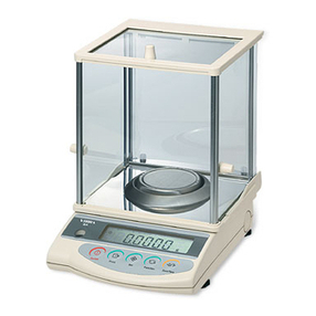
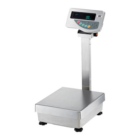
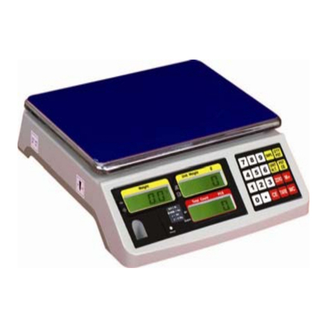
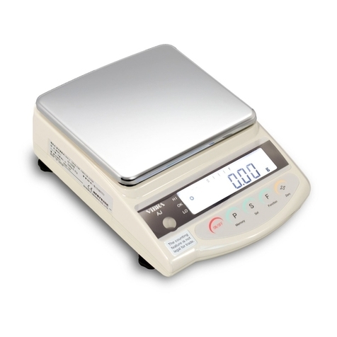
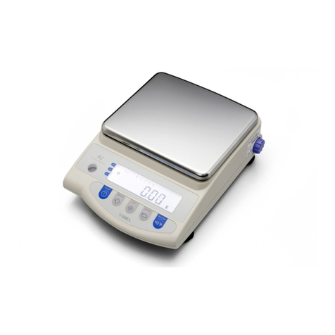
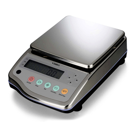
Vibra GZ II Series User manual

GZ II Series
Service Manual
SHINKO DENSHI CO., LTD.

Table of Contents
Chapter 1 Appearance............................................................................................1
1-1 Appearance of the Round Pan Type ............................................................................1
1-2 Appearance of the Square Pan Type ...........................................................................1
Chapter 2 Configuration of the Electric Components ..............................................2
2-1 Entire Wiring Diagram....................................................................................................2
Chapter 3 Troubleshooting......................................................................................4
3-1 Inspection Procedure.....................................................................................................4
3-2 Quick Reference Guide for Troubleshooting.................................................................5
3-3 Initial Inspection.............................................................................................................7
3-4 Inspection of the Electrical Components.......................................................................8
Chapter 4 Adjustment and Setting Procedures.....................................................12
4-1 Span Adjustment (CAL) ...............................................................................................12
4-2 Corner Error Adjustment..............................................................................................13
4-3 Coefficient Data Correction and Linearity Adjustment Procedures.............................14
4-4 How to Check (Enter) the Coefficient Data..................................................................15
4-5 LinearityAdjustment ....................................................................................................17
Chapter 5 Replacement Procedures.....................................................................18
5-1 Procedure for Replacing the Mechanical Sensor Assembly.......................................18
5-2 Procedure for Replacing the Tuning Fork Assembly...................................................21
5-3 Procedure for Replacing the GZDSP-2 Board ............................................................24
5-4 Procedure for Replacing the GZOSC-1 Board............................................................27
5-5 Procedure for Replacing the GZLF Board...................................................................28
Chapter 6 Replacement Procedures for Options...................................................29
6-1 Procedure for Replacing the Insulating Barrier ...........................................................29
6-2 Procedure for Replacing the GZJP Board...................................................................30
6-3 Procedure for Replacing the GZ Printer Output (R1)..................................................31
6-4 Procedure for Replacing the GZRS232C Output (R2)................................................33
6-5 Procedure for Replacing the GZRS422C Output (R4)................................................35
6-6 Procedure for Replacing the GZ Printer Output + GZRS232C Output (R5)...............37
6-7 Procedure for Replacing the GZ Relay Contact Output + External Tare (LM1)..........39
6-8 Procedure for Replacing the GZ Relay Contact Output + RS232C Output (LM3)......41
6-9 Procedure for Replacing the GZBCD Output..............................................................43
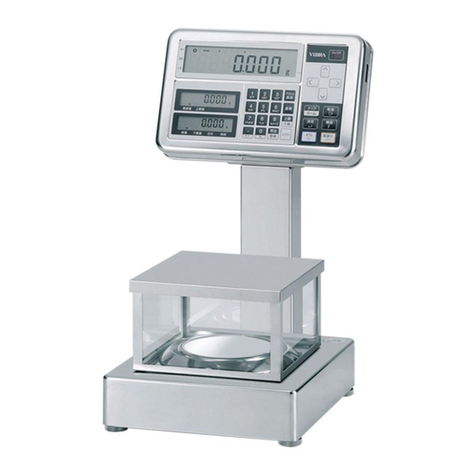
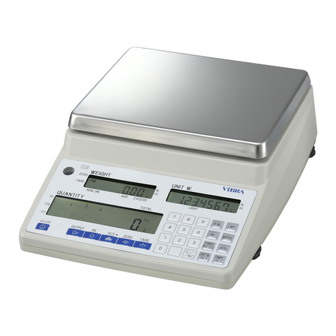
1
Chapter 1 Appearance
1-1 Appearance of the Round Pan Type [1000–2000 g]
1-2 Appearance of the Square Pan Type [6000–15 kg]
(Figure 1-1)
(Figure 1-2)

2
Chapter 2 Configuration of the Electric
Components
2-1 Entire Wiring Diagram
(1) Power Box Type
(Figure 2-1)
Weighing part
Mechanical part
Power box
GZOSC-1 board
Display part
GZLF board
GZDSP-2 board
GZSW-2 board
ON/OFF
Print
Limit/Add
Zero/Tare
Set/Switch

3
(2) Battery Type
(Figure 2-2)
Weighing part
Mechanical part
GZOSC-1 board
Display part
Battery box
GZSW-2 board
GZBDSP-1 board
ON/OFF
Print
Limit/Add
Set/Switch
Zero/Tare

4
Chapter 3 Troubleshooting
3-1 Inspection Procedure
(Figure 3-1)
Is “
“ displayed?
Start
Perform the initial
inspection.
Weight
display mode
Is the displayed
weight stable?
Is the display
normal during
measurement?
Check the
stoppers. Readjustment
Check the corner
error.
Adjust the corner
error
.
Check the
linearity error.
Adjust the
linearity.
The instrument
is normal.
Check the
memory.
Reenter the
coefficient.
Return to the
initial inspection.
Check the output
waveform.
The mechanical
unit has failed.
Replace the
mechanical unit.
Replace the
tuning fork
assembly.
Is the
power supply
voltage in the circuit
normal?
The GZDSP-2
(GZBDSP-1)
board has failed.
The GZLF board
has failed.
Replace the
GZLF board.
Return to the
initial inspection.
The GZOSC-1
board has failed.
The GZOSC-1
board is normal.
The tuning fork
assembly has
failed.
Replace the
GZOSC-1
board.
Is the power
box connected?
Is the battery
box connected?
Connect the
power/battery
box.
Return to the
start.
Are all
necessary
connecters
connected?
Connect all
necessary
connectors.
Return to the
initial inspection.
The instrument
is normal.
Is the GZLF
board normal?
Replace
the GZDSP-2
(GZBDSP-1)
board.

5
3-2 Quick Reference Guide for Troubleshooting
Symptoms Probable causes Remedies
1. The GZDSP-2 (GZBDSP-1) board has
failed. 1. Replace the GZDSP-2
(GZBDSP-1) board.
2. The power/battery box has failed. 2. Replace the power/battery
box.
3. The connection cables inside the balance
are incorrectly connected. 3. Check the connection of
the cables.
Noting is displayed.
4. The dry-cell batteries have run out
(battery box type). 4. Replace the dry-cell
batteries.
1. The wrong kind of pan is being used. 1. Check the pan.
2. The tuning fork assembly or mechanical
unit has failed. 2. Replace the tuning fork
assembly or mechanical
unit.
3. The GZDSP-2 (GZBDSP-1) board has
failed. 3. Replace the GZDSP-2
(GZBDSP-1) board.
4. The coefficient data is improperly set
(when the data was entered). 4. Check the coefficient data.
After “ ” is
displayed,
“ ” or “ ”
is displayed.
5. The coefficient has changed due to static
electricity or noise. 5. Check the coefficient data.
1. Something is in contact with the stopper. 1. Check the mechanical
stopper.
2. Something is in contact with the
calibration weight unit. 2. Check the area around the
calibration weight unit.
3. Something is in contact with the pan (or
pan base). 3. Check the area around the
pan.
4. There is foreign matter in the balance. 4. Check the area around the
balance’s mechanical part.
5. The tuning fork assembly or mechanical
unit has failed. 5. Replace the tuning fork
assembly or mechanical
unit.
6. The balance is being affected by wind or
vibration, etc. 6. Check the area around the
balance.
The displayed value is
unstable.
Poor repeatability.
The zero point changes.
7. The GZOSC-1 board has failed. 7. Replace the GZOSC-1
board.
1. The tare is too heavy. 1. Check the tare weight.
2. The coefficient data is improperly set. 2. Check the coefficient data.
3. The coefficient has changed due to static
electricity or noise. 3. Check the coefficient data.
4. Span adjustment has been made with
erroneous weights. 4. Check the adjustment
weights.
“ ” is displayed
before the weighing
capacity is reached.
5. Something is in contact with the
calibration weight unit. 5. Check the area around the
calibration weight unit.
1. The tuning fork assembly or mechanical
unit has failed. 1. Replace the tuning fork
assembly or mechanical
unit.
2. The GZDSP-2 (GZBDSP-1) board has
failed. 2. Replace the GZDSP-2
(GZBDSP-1) board.
3. The coefficient data is improperly set
(when the data was entered). 3. Check the coefficient data.
The span is significantly
incorrect.
4. The coefficient has changed due to static
electricity or noise. 4. Check the coefficient data.
1. The tuning fork assembly or mechanical
unit has failed. 1. Replace the tuning fork
assembly or mechanical
unit.
2. The coefficient data is improperly set. 2. Check the coefficient data.
3. The coefficient has changed due to static
electricity or noise. 3. Check the coefficient data.
4. Span adjustment has been made with
erroneous weights. 4. Check the adjustment
weights.
Poor linearity
5. The GZOSC-1 board has failed. 5. Replace the GZOSC-1
board.
(Table 3-1)

6
Symptoms Probable causes Remedies
1. The mechanical section has failed. 1. Replace the mechanical
unit.
Improper corner error
2. Something is in contact with the pan (or
pan base). 2. Check the area around
the pan.
1. The GZDSP-2 (GZBDSP-1) board has
failed. 1. Replace the GZDSP-2
(GZBDSP-1) board.
2. The power/battery box has failed. 2. Replace the power/battery
box.
The display turns off
during measurement.
3. The batteries have run out. 3. Replace the batteries.
“ ” is displayed.
1. When span adjustment is performed
with external weights, the reference
weights are less than 50% of the
weighing capacity.
1. Set reference weights so
that they weigh 50% or
more of the weighing
capacity.
“ ” is displayed.
1. During semi-auto span adjustment,
adjustment was made with something
placed on the pan.
1. Remove the object on the
pan.
“ ” is displayed.
1. The tuning fork assembly or mechanical
unit has failed. 1. Replace the tuning fork
assembly or mechanical
unit.
“ ” is
displayed. 1. The internal coefficient has
inadvertently been changed. 1. Check the coefficient
data.
1. During addition operation, the additions
are overlapped. 1. Adhere to correct
operating procedures.
“ ” is
displayed. 2. During addition operation, a 0 (zero) or
negative value was added. 2. Check the added weight.
(Table 3-2)

7
3-3 Initial Inspection
Make sure the balance is not being affected by wind or vibration.
Make sure the pan base and pan are properly in place.
Make sure no foreign objects are present under the pan (or pan base).
Make sure the right kind of pan is used.
Make sure the balance is placed on a stable surface.
Make sure the balance is property leveled.
Make sure the power/battery box is properly connected.

8
3-4 Inspection of the Electrical Components
* The value of Type B is only different in CN-4.
In other check points, the value is shared between Type B and Type D.
1. Power supply voltage check
CN4-… +11 to +13 V (Type B: +6.00 to +10.32 V)
2. In-circuit power supply voltage check
CN2-….. +4.88 to +5.12 V
CN2-….. −4.88 to −5.12 V
3. Signal waveform check
TP0-CN2(tuning fork waveform input)
TP0-CN2(temperature waveform input)
TP0-IC1
64 (main clock)
(Figure 3-2)

9
Inspect the following parts of the GZDSP-2 board.
(Figure 3-3)

10
Inspect the following parts of the GZBDSP-1 board.
(Figure 3-4)
Connected to the battery box

11
GZOSC-1 board check
1. Check preparation
Set up an oscilloscope and power off the balance. Touch the probe to the CN2 pins.
(Figure 3-5)
2. How to check
(1) Oscillate within three seconds after powering on the balance (in the case of a recheck,
wait for 10 seconds or more after powering off the balance).
(2) Place a load that is half the weighing capacity and check the amplitudes and phase
differences of CH-1 and CH-2.
Amplitude (P-P) … CH-1: 150 mV or more (average: 750 mV)
CH-2: 700 mV or more (average: 3.5 V)
(Figure 3-6)
(Phase difference) … 50 to 120°/Time base: scale mark 0.3 to 0.8 (0.2 msec/DIV)
Voltage and frequency ranges of the
oscilloscope
Voltage range
CH1: 0.1 to 0.5 V/DIV
CH2: 1 V/DIV
Frequency range
0.2 msec/DIV
Power: +4 to +6 V
GND
Power: −4 to −6 V
Square wave output (tuning fork)
Square wave output (temperature)

12
Chapter 4 Adjustment and Setting Procedures
4-1 Span Adjustment (CAL)
* = “Set/Switch” key
= “Zero/Tare” key
1. The span can be adjusted when the weight of standard test weights is half the weighing
capacity or more. However, the weight of standard test weights should be as close to the
weighing capacity as possible.
2. To cancel span adjustment, press the “set” key. The display will then return to weight
display mode.
“ ”: The weight of standard test weights exceeds the weighing capacity.
“ ”: The weight of standard test weights is less than half of the weighing
capacity.
“ ”: The error of the displayed weight exceeds 1%.
Press the “ON/OFF” key to turn the display on.
Press and hold until the display changes from “ ”
to “ ,” and then release it.
With no sample placed on the pan, press while pressing
, and then release them at the same time.
“ ” blinks and the zero-point will be adjusted
automatically.
When zero-point adjustment is complete, “ ” is
displayed.
Place standard test weights on the center of the pan. The
display blinks and the span will be adjusted automatically.
When span adjustment is complete, the display stops blinking
and returns to weight display mode.

13
4-2 Corner Error Adjustment
(1) Remove the unit cover (Refer to Figure 5-1).
(2) Replace the pan and pan base and adjust the adjuster so that the balance is
horizontal.
(3) Adjust the corner error according to the following corner error adjustment table.
(Figure 4-2)
To the GZDSP board
Corner error
adjusting bolt (A)
Corner error
adjusting bolt (B)
(Figure 4-1)
Symbols
Descriptions
Positive from the center
Negative from the center
Turn the adjusting bolt counterclockwise.
Turn the adjusting bolt clockwise.

14
4-3 Coefficient Data Correction and Linearity Adjustment
Procedures
(1) Coefficient data correction procedure
(2) Linearity adjustment procedure
The coefficient data has changed due to static electricity or
noise.
Enter the coefficient data.
(See the coefficient label on the Figure 4-3.)
Span adjustment
Performance check
Poor linearity
Enter the coefficient data.
(See the coefficient label on the Figure 4-3.)
Linearity adjustment
“CAL 2”
Performance check

15
4-4 How to Check (Enter) the Coefficient Data
When the GZDSP-2 (or GZVDSP-1) board is replaced, or the coefficient data is lost due to
static electricity, etc., reenter the coefficient data according to the following procedure.
1. Location of the coefficient data label
2. How to read the data sheet
Data sheet
(Figure 4-3)
* After replacing the mechanical
unit, put the data sheet for the
new unit on top of the old data
sheet.
Tuning fork No.
Program No.
Adr. 60 to 66, from the left
Adr. 67 to 6D, from the left
Adr. 6E to 74, from the left
Adr. 75 to 7B, from the left
Adr. 7C to 82, from the left
Adr. 83 to 85, from the left
(Figure 4-4)

16
3. How to Check (Enter) the Coefficient Data
“ON/OFF” key
“Set/Switch” key
“Zero/Tare” key
Press while pressing and to turn the display on. Release the
keys when “ ” is displayed.
After a while, the balance will be in weight display mode. At that time, press
and hold and release it for a moment when “ ” is displayed.
Press and hold again until “ ” is displayed.
Pressing briefly displays “ .”
(If no change is needed, press to proceed to the next address.)
Pressing displays “ ”. Every time is pressed after that,
the rightmost digit changes from “ ” to “ ”, “ ”, and “ ”.
After the highest digit is selected, the rightmost digit moves to the left every time is pressed.
(Ex. “ ”)
Pressing again causes a number to appear on the extreme right.
(Ex. “ ”)
Pressing again causes the rightmost digit to change as shown above.
Select the desired number and press . (Ex. “ ”)
When the entry is complete, the balance will switch back to weight display
mode.
Press to turn the display on.
Press while pressing and to turn the display on.
When “ ” is displayed, release the keys.
While pressing , press and release them at the same time.
After a while, the balance enters weight display mode. Press to finish.

17
4-5 Linearity Adjustment
Table of Cumulative Weights for Linearity Adjustment
(Table 4-1)
Weights to
be used
Type
Display
“ON/OFF” key
“Set/Switch” key
“Zero/Tare” key
Press while pressing and to turn the display on.
When “ ” is displayed, release the key.
After a while, the balance enters weight display mode. Press and hold
until the display change from “ ” to “ .”
Check that nothing is on the pan. Then, press while pressing and
release the keys at the same time.
“ ” blinks and the zero-point will be adjusted automatically.
For a three-split,
Press
After “ ” is displayed, the balance will switch back to weight
display mode. (Adjustment mode)
Pressing to turn the display off and again to turn the display on will
return the balance to normal mode.

18
Chapter 5 Replacement Procedures
5-1 Procedure for Replacing the Mechanical Sensor Assembly
1. How to Remove the Unit Cover
(1) Power off the balance and remove the pan and pan base.
(2) Remove the unit cover mounting screws A (4) with a Phillips-head screwdriver.
(3) Remove the unit cover.
(Figure 5-1)
2. How to Install the Unit Cover
(1) Reassemble the unit cover taking care not to catch connecting cords in between
surfaces.
(2) Install unit cover mounting screws A (4) with a Phillips-head screwdriver.
(3) Put the pan base and pan in place.
Screws A
Table of contents
Other Vibra Scale manuals

Vibra
Vibra CG-K User manual

Vibra
Vibra CJ series User manual

Vibra
Vibra AJ-CESeries User manual

Vibra
Vibra VIBRA ALC 3 User manual

Vibra
Vibra GZII-CEx Series User manual

Vibra
Vibra SJ-E Series User manual

Vibra
Vibra AJ Series User manual

Vibra
Vibra ALE-NC Series User manual

Vibra
Vibra HJ-K Series User manual

Vibra
Vibra HJ-KCE series User manual

Vibra
Vibra HJ-KE Series User manual

Vibra
Vibra SJ-CE series User manual

Vibra
Vibra CJ-E series User manual

Vibra
Vibra AJ220NT/DBNT User manual

Vibra
Vibra SA/CA Series User manual

Vibra
Vibra AF-220 User manual

Vibra
Vibra AJH Series User manual

Vibra
Vibra VIBRA HAW 3 User manual

Vibra
Vibra DJ series User manual

Vibra
Vibra FZ623E Series User manual