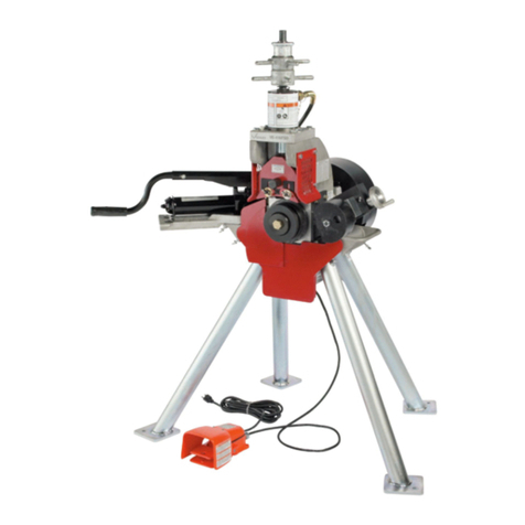
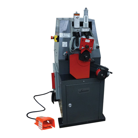
Victaulic VG412 Manual

46046
O

VG412
1
TABLE OF CONTENTS
HAZARD IDENTIFICATION 2
OPERATOR SAFETY STRUCTIONS 2
TOOL NOMENCLATURE 6
RECEIVING TOOL 7
TOOL SET-UP 9
CUTTING AND GROOVING 24
DISASSEMBLY, CLEANING & STORING 34
MAINTENANCE 36
TROUBLESHOOTING 39
PARTS & ACCESSORIES 40
GROOVE SPECIFICATIONS 44

VG412
2
HAZARD IDENTIFICATION
READ THIS FIRST
Definitions for identifying the various hazard levels shown on warning labels or to indicate proper safety
procedures in this Manual are provided below.
This safety alert symbol indicates important safety messages on warning labels and in this manual. When
you see this symbol be alert to the possibility of personal injury and carefully read and fully understand
the message that follows.
OPERATOR SAFETY STRUCTIONS
This tool is designed only for cut grooving pipe. To accomplish this function requires some dexterity and
mechanical skills, as well as sound safety habits. Although this tool is manufactured for safe dependable
operation, it is impossible to anticipate those combinations of circumstances which could result in an
accident. The following instructions are recommended for safe operation of the tool. The operator is
cautioned to always practice "Safety First" during each phase of use, including setup and maintenance of
this unit. It is the responsibility of the owner, lessee or user of this tool to ensure that all operators
receive, read and understand this manual and are fully trained to operate this tool.
GENERAL
1. Read and understand this Manual before operating or performing maintenance on this tool.
Become familiar with the tool’s operations, applications and limitations. Be particularly aware of its
specific hazards. Store this manual in a clean area and always at a readily available location.
Additional copies at no charge are available upon request by writing or phoning the Victaulic Tool
Company.
2. Use only recommended accessories. Use of improper accessories may be hazardous. See
Accessories on page 40.
3. This tool is designed ONLY for cut grooving of pipe sizes, materials and wall thicknesses
outlined under Tool Rating on page 8 and Tool Bit Selection on page 38.

VG412
3
TOOL SET-UP
1. Ground the Power Drive. Be sure the power drive is connected to an internally grounded electrical
system.
2. Avoid dangerous environments. Don’t use the machine in damp or wet locations. Don’t use the tool
on sloped or uneven ground or floor. Keep work area well illuminated. Allow sufficient space to
operate tool and accessories properly and for others to pass safely.
3. Prevent back injury. During tool set-up, one person cannot safely handle the tool assembly because
it weighs 145 lbs ( 66kg). Two people are needed to safely handle the assembly. If a hoist is available
use it to lift the tool assembly into position.
4. Only use power drive supplied with tool. Use of a different power drive may result in personal
injury, poorly cut pipe ends or grooves and damage to the tool.
5. Pipe must be properly prepared in accordance with Victaulic pipe preparation specifications.
OPERATING TOOL
1. Inspect the equipment. Prior to starting the tool, check the movable parts for any obstructions. Be
sure that guards and tool parts are properly installed and adjusted.
2. Prevent accidental startings.Un-plug the tool when making adjustments and performing
maintenance.
3. Operate with foot switch only. The power drive must be operated with a safety foot switch as the
operator will require it to operate the tool safety.
4. Keep hands away from tool holders and gears during operation. Tool holders and gear can crush
or cut fingers and hands.
5 Never reach inside pipe ends during operation.
6. Do not over reach. Keep your proper footing and balance at all times. Be sure you can reach foot
switch safely at all times. Do not reach across tool or pipe. Keep hands and loose tools away from
moving parts.
7. Wear safety glasses and footwear.
8. Keep work area clean. Cluttered areas, benches and slippery floors invite accidents.
9. Wear ear protection if exposed to long periods of very noisy shop operations.

VG412
4
10. Keep visitors away. All visitors should be kept a safe distance from the work area.
11. Keep alert. Do not operate tool if ill or drowsy from medication or fatigue. Avoid horseplay around
tool and keep bystanders a safe distance from tool and pipe being grooved.
12. Do not operate tool at speeds exceeding those specified in this manual.
13. Wear proper apparel. Never wear loose clothing (unbottoned jackets or loose sleeve cuffs) loose
gloves or jewelry that can get caught in moving parts
14. Do not force tool.It will do the job better and safer at the rate for which it was designed.
15. Support work. Support long pipe with a pipe stand secured to the floor or ground.
16. Do not misuse tool. Perform only the functions for which the tool is designed. Do not overload the
tool.
17. Keep hands away from moving parts.The cutting tool “rotates” around the pipe when the power
drive is switched on. The pipe cut off head contacts the actuator bar as it passes by. Keep hands away
from the actuator while the tool is in operation.
TOOL MAINTENANCE
1. Unplug power cord prior to servicing. Repair should be attempted only by authorized personnel.
Always unplug power drive before servicing or making any adjustment.
2. Maintain tool in top condition.Keep tool clean for best and safest performance. Follow lubricating
instructions.
POWER REQUIREMENTS

VG412
5
Power must be supplied through a safety foot switch to assure safe operation. Be sure the power drive is
properly grounded in accordance with Article 250 of the National Electrical Code. If an extension cord is
to be used, see Extension Cord Requirements on this page for cord size recommendations.
EXTENSION CORD REQUIREMENTS
When pre-wired outlets are not available and an extension cord must be used, it is important to use the
proper cord size (e.g. . conductor size American Wire gauge). Cord size selection is based upon tool
rating (amps) and cord length (feet). Use of a cord size (gauge) thinner than required will cause a
significant voltage drop at the power drive while the tool is operating. The voltage drop may cause
damage to the power drive and can result in failure of the tool to operate properly. Use of a heavier than
necessary cord size (gauge) is acceptable.
Listed in the chart below are recommended cord size (gauge) for cord lengths up to and including 100
feet. Use of extension cords beyond 100 feet in length should be avoided.
TOOL
MODEL POWER DRIVE RATING
VOLT/AMPS CORD LENGTHS
25’ 50’ 100’
VG412 115/15 12 Ga. 12 Ga. 10 Ga.

VG412
6
TOOL NOMENCLATURE
Figure 1

VG412
7
RECEIVING TOOL
VG 412 tools are packed individually in sturdy containers, designed for use in reshipping tools upon
completion of the rental contract, when applicable.
NOTE: Be sure to save original shipping container for return shipment of rental tools.
Upon receipt of tool, make sure all necessary parts are included. If any parts are missing, notify your
Victaulic distributor or Victaulic representative.
CONTAINER CONTENTS
(See page 8 for list of contents)
Figure 2

VG412
8
CONTAINER CONTENTS
1. Hinged main frame with gear plate halves installed. (Note: weight = 138 pounds (63Kg).
2. Motor, footswitch, power cord with plug assembly.
3. Motor mount and mounting hardware.
4. Cutoff blades.
5. Grooving bits for 4"- 6" D.I. and 8" - 12" D.I., one set each.
6. Tool stand with four legs.
7. Riser blocks for 6" - 10" D.I. (12" mounted on frame)
8. One cutoff blade assembly.
9. Two grooving blade assembly.
10. One 4" cutoff/groove component kit.
11. One set D.I. rigid groove spacer blocks.
12. Two tool operating and maintenance manuals.
TOOL RATING
The standard VG 412 tool is supplied with the necessary components to cut off and cut groove 4" - 12"
D.I. pipe with rigid grooves for use with Victaulic grooved piping products for AWWA ductile piping.
For grooving to other specifications and other materials, see tool bit selection chart on page 38.
Component parts for other materials must be purchased separately.

VG412
9
TOOL SET-UP
This section has four parts: (1) general set up instructions: (2) set up instructions for short pipes (less than
12 inches): (3) set up instructions for long pipes: and (4) set up instructions for tool installed around the
pipe, for example, in the field with a pipe already in position.
GENERAL
The VG 412 is intended for shop or field use. It will cut and groove 4" through 12" (100 - 300mm) pipe
from full lengths down to approximately 12" in length. Pipe must be adequately supported as the unit is
not intended to carry the weight at the pipe. (Support both ends of pipe if necessary. ) Short lengths of
less than 36" can be accomplished with the use of the pipe stand. The tool and pipe supports must be
placed on level ground. See Operator Instructions, Tool Set Up #2, Dangerous Environments.
GENERAL PROCEDURES
Remove all components from the container, and be sure that all necessary items are included. See list
under Receiving Tool.

VG412
10
1. Select location for tool and pipe stand (s). Choose a location that has:
a. The required power. Consult the power requirements on page 4.
b. The space necessary to adequately handle the pipe to be grooved.
c. A level and even surface for tool, pipe stand (s), and footing.
SET UP TO CUT OFF SHORT PIPES:
The procedures to set up and cut off a short pipe are:
1. Insert legs (4) into sockets on bottom of tool support table and tighten bolts finger tight.
Figure 3

VG412
11
2. Set tool upright. Adjust legs to achieve a level tool and assure that all four (4) of the legs are resting
on the floor to prevent the tool from rocking, and tighten with a wrench.
Figure 4
3. Attach the motor mount to the main frame using four (4) wing handle clamp screws.
Figure 5

VG412
12
4. Attach the motor to the top of the motor mount, do not tighten. Rotate chuck to align with hex drive
of the pinion and move motor forward to engage. Tighten drive motor chuck with chuck key. Tighten
wing handle clamp screws to secure motor in place.
Figure 6
5. Select two (2) riser blocks for the size of pipe to be cut and grooved. Attach the riser blocks to the
base plate inside the main frame. NOTE: The permanently mounted base plates serve as the riser
blocks for the 12” size.
Figure 7

VG412
13
6. Adjust the clamp screws, on the lower half of the frame, so that there is an opening at least 1/2” larger
than the size of pipe to be grooved.
7. Insert pipe betweem riser blocks and clamp screws.
Figure 8
8. Tighten clamp screws on the pipe evenly. Pipe must contact both riser blocks squarely, and with
sufficient force to resist rotation of the pipe during cut off and grooving. NOTE: Check the
tightness of the clamp screws throughout the cutting and grooving operations, and retighten if
necessary.
Figure 9

VG412
14
9. Engage one-half (1/2) of gear plate over the track rollers on the bottom half of the frame and rotate
upward until the gear half is centered on the pinion gear.
Figure 10
10. Engage the other half of the gear plate over the track rollers, and bring the two halves together.
11. Engage and secure the swing bolts or swing latch by tightening the hex nuts securely.
Figure 11

VG412
15
12. Select the spacer block for the size of pipe to be grooved.
13. Attach cutoff head assembly on top of spacer block with four (4) allen head screws. NOTE:
Retract cutoff blade to clear pipe if necessary by pressing detent lever and turning crank handle
clockwise. Tighten screws securely. DO NOT have grooving blade assemblies on gear plate while
cutting.
Figure 12
14. Retract motor. Rotate gear plate manually completely around the pipe to find the “high spot”. Press
the dentent lever and turn crank counter clockwise until there is approximately 1/32” to 1/16”
clearance between pipe and edge of cutoff blade at the “high spot”.
15. Rotate the gear plate until the blade assembly is at the bottom near the actuator bar.
Figure 13

VG412
16
16. The actuator bar should be set to engage the star wheel with approximately 1/32" clearance at the
bottom of the star wheel. Fine adjustment can be made with the two wing screws found in the slots of
the actuator mechanism base.
Figure 14
17. Prepare to support the piece of pipe that is being cut off.
18. Plug in the power drive and activate tool by depressing foot switch. After two or three revolutions the
cutoff blade will contact pipe intermittently, and after a few more revolutions will be cutting
completely around the O.D. of the pipe. Because the cut started intermittently, it will end
intermittently, meaning it will be through the pipe wall at some places before others
19. After pipe is completley cut off, remove foot from switch and allow tool to stop rotating
20. Unplug power cord to power drive until further needed.
21. Loosen wing screws and retract actuator bar (can be tapped with a soft mallet)
To cutoff another pipe return to step number 7.

VG412
17
SET UP FOR TOOL INSTALLED AROUND PIPE
1. Remove grooving head and cut off head from front of gear plate.
2. Separate the two halves of the gear plate by loosening the hex nuts at the joint.
3. Release the gear plate swing plates, and separate the gear halves and remove the lower half from the
main frame. Then roll the other gear half out of engagement with the pinion and remove it from the
main frame.
Figure 15
Figure 16

VG412
18
4. Select the proper pair of riser blocks from those provided with the tool, and attach to the upper frame
with screws provided. The permanently mounted base plates are for the 12” size. Each riser block has
the pipe size marked on it.
Figure 17
5. Adjust the clamp screws on the lower half of the frame to at least 1/2” larger than pipe size being cut
and grooved.
6. Slide the frame over the pipe end near to the point where the pipe is to be cut and grooved. Where this
is not possible, the frame may be hinged open by opening the swing bolts. Then the frame may be
hinged open and assembled around the pipe. Close the swing bolts and retighten.
Figure 18

VG412
19
7. Tighten clamp screws on the pipe evenly and with sufficient force to resist rotation of the pipe during
cut off and grooving. NOTE: Check the tightness of the clamp screws throughout the cutting and
grooving operation, and retighten if necessary
8. Attach the motor mounting bracket to the rear or the frame.
Figure 19
9. Attach the motor to the bracket, with the wing screws, but do not tighten. Align the hex in the drive
socket with the hex on the drive shaft by turning the chuck by hand and slide the socket over the drive
hex. Tighten the chuck and tighten the mounting wing screws securely.
Figure 20
Table of contents
Other Victaulic Tools manuals

Victaulic
Victaulic AGS TM-RG5200i Manual

Victaulic
Victaulic VE26 Series Manual

Victaulic
Victaulic VE46 Series Manual

Victaulic
Victaulic VE460 Manual

Victaulic
Victaulic RG3400 Manual

Victaulic
Victaulic RG2910 Manual

Victaulic
Victaulic PC3110 Manual

Victaulic
Victaulic VE272SFS Manual

Victaulic
Victaulic VE106 Groove-N-Go Manual

Victaulic
Victaulic VE416FS Manual

Victaulic
Victaulic VE416FS Manual

Victaulic
Victaulic RG1210 Manual

Victaulic
Victaulic OGS RG3212 Manual

Victaulic
Victaulic VE414MC Manual

Victaulic
Victaulic PC3110 Manual

Victaulic
Victaulic RG1200 Manual

Victaulic
Victaulic EndSeal TM-VE414MC Manual

Victaulic
Victaulic VE12 Manual

Victaulic
Victaulic VE450FSD Manual

Victaulic
Victaulic 746 Series User manual