2
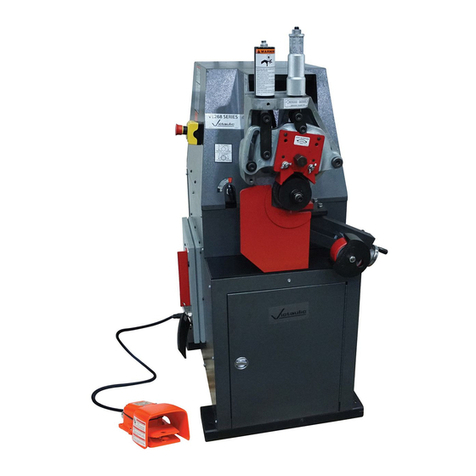
VE266FS
Read this First – Hazard Identification
Definitions for identifying the various hazard levels shown on warning labels or to indicate proper
safety procedures in this Manual are provided below.
This safety alert symbol indicates important safety messages on warning labels and in
this manual. When you see this symbol be alert to the possibility of personal injury and
carefully read and fully understand the message that follows.
The use of the word “DANGER” always signifies an
immediate hazard with a likelihood of severe personal
injury or death if instructions, including recommended
precautions, are not followed.
The use of the word “WARNING” signifies the
presence of hazards or unsafe practices which could
result in severe personal injury or death if
instructions, including recommended precautions, are
not followed.
The use of the word “CAUTION” signifies possible
hazards or unsafe practices which could result in
minor injury, product or property damage if
instructions, including precautions, are not followed.
NOTICE
The use of the word “NOTICE” signifies special
instructions which are important but not related to
hazards.
INDEX
Hazard Identification . . . . . . . . . . . . . . . . . . . . . . . 2
Operator Safety Instructions . . . . . . . . . . . . . . . . . 3
General. . . . . . . . . . . . . . . . . . . . . . . . . . . . . . . . 3
Tool Setup . . . . . . . . . . . . . . . . . . . . . . . . . . . . . 3
Operating Tool . . . . . . . . . . . . . . . . . . . . . . . . . . 3
Tool Maintenance . . . . . . . . . . . . . . . . . . . . . . . 3
Introduction. . . . . . . . . . . . . . . . . . . . . . . . . . . . . . . 4
Power Drive . . . . . . . . . . . . . . . . . . . . . . . . . . . . 4
Power Requirements. . . . . . . . . . . . . . . . . . . . . 4
Extension Cord Requirements. . . . . . . . . . . . . 4
Tool Nomenclature . . . . . . . . . . . . . . . . . . . . . . . . . 5
Receiving Tool. . . . . . . . . . . . . . . . . . . . . . . . . . . . . 6
Container Contents. . . . . . . . . . . . . . . . . . . . . . 6
Tool Setup . . . . . . . . . . . . . . . . . . . . . . . . . . . . . . . . 6
Pre-Operation Adjustments . . . . . . . . . . . . . . . . . 10
Grooving Rolls . . . . . . . . . . . . . . . . . . . . . . . . . 10
Pipe Preparation . . . . . . . . . . . . . . . . . . . . . . . 10
Groovable Pipe Lengths . . . . . . . . . . . . . . . . . 10
Roll Guard Adjustment . . . . . . . . . . . . . . . . . . 11
Pipe Stabilizer Adjustment. . . . . . . . . . . . . . . 13
Groove Diameter Stop Adjustment . . . . . . . . 15
Grooving Operation . . . . . . . . . . . . . . . . . . . . . . . 16
Roll Changing . . . . . . . . . . . . . . . . . . . . . . . . . . . . 18
Roll Removal Procedure . . . . . . . . . . . . . . . . . 18
Arbor Shaft Removal Procedure. . . . . . . . . . . 20
Roll Installation Procedure . . . . . . . . . . . . . . . 20
Upper Roll – All sizes. . . . . . . . . . . . . . . . . . 20
Lower Roll –
³⁄₄
" and 1 - 1
¹⁄₂
" sizes . . . . . . . 21
Arbor Shaft Installation Procedure . . . . . . . . 22
Roll Installation Procedure . . . . . . . . . . . . . . . 22
Lower Roll – 2" and larger sizes . . . . . . . . . 22
Maintenance . . . . . . . . . . . . . . . . . . . . . . . . . . . . . 23
General. . . . . . . . . . . . . . . . . . . . . . . . . . . . . . . 23
Lubrication. . . . . . . . . . . . . . . . . . . . . . . . . . . . 23
Hydraulic Systems . . . . . . . . . . . . . . . . . . . . . 24
Parts Ordering Information. . . . . . . . . . . . . . . 25
Accessories . . . . . . . . . . . . . . . . . . . . . . . . . . . . . . 26
Victaulic Adjustable Pipe Stands . . . . . . . . . 26
Stabilizer Assembly . . . . . . . . . . . . . . . . . . . . 26
Optional Rolls. . . . . . . . . . . . . . . . . . . . . . . . . . 26
Troubleshooting . . . . . . . . . . . . . . . . . . . . . . . . . . 27
Tool Rating and Roll Selection . . . . . . . . . . . . . . . 29
Standard and “ES” Rolls . . . . . . . . . . . . . . . . . 29
Rolls for Stainless Steel (RX Rolls) . . . . . . . . . 30
Rolls for Copper Tubing . . . . . . . . . . . . . . . . . 30
Roll Groove Specifications
Steel Pipe and All Materials Grooved
with Standard and RX Rolls . . . . . . . . . . . . 32
Steel Pipe and All Materials Grooved
with “ES” Rolls. . . . . . . . . . . . . . . . . . . . . . . 34
Drawn Copper Tubing
U.S. Standard – ASTM B-88 . . . . . . . . . . . . 35
British Standard – BS 2871. . . . . . . . . . . . . 36
DIN German Standard – DIN 1786. . . . . . . 37
Australian Standard – AS 1432 . . . . . . . . . 38
Dimensions . . . . . . . . . . . . . . . . . . . . . . . . . . . . . . 39
Seamless and Welded Steel Pipe . . . . . . . . . . 39
Drawn Copper Tubing . . . . . . . . . . . . . . . . . . 39
TM-VE266FS.2690 Rev.B Page 2 Friday, November 10, 2000 2:51 PM
