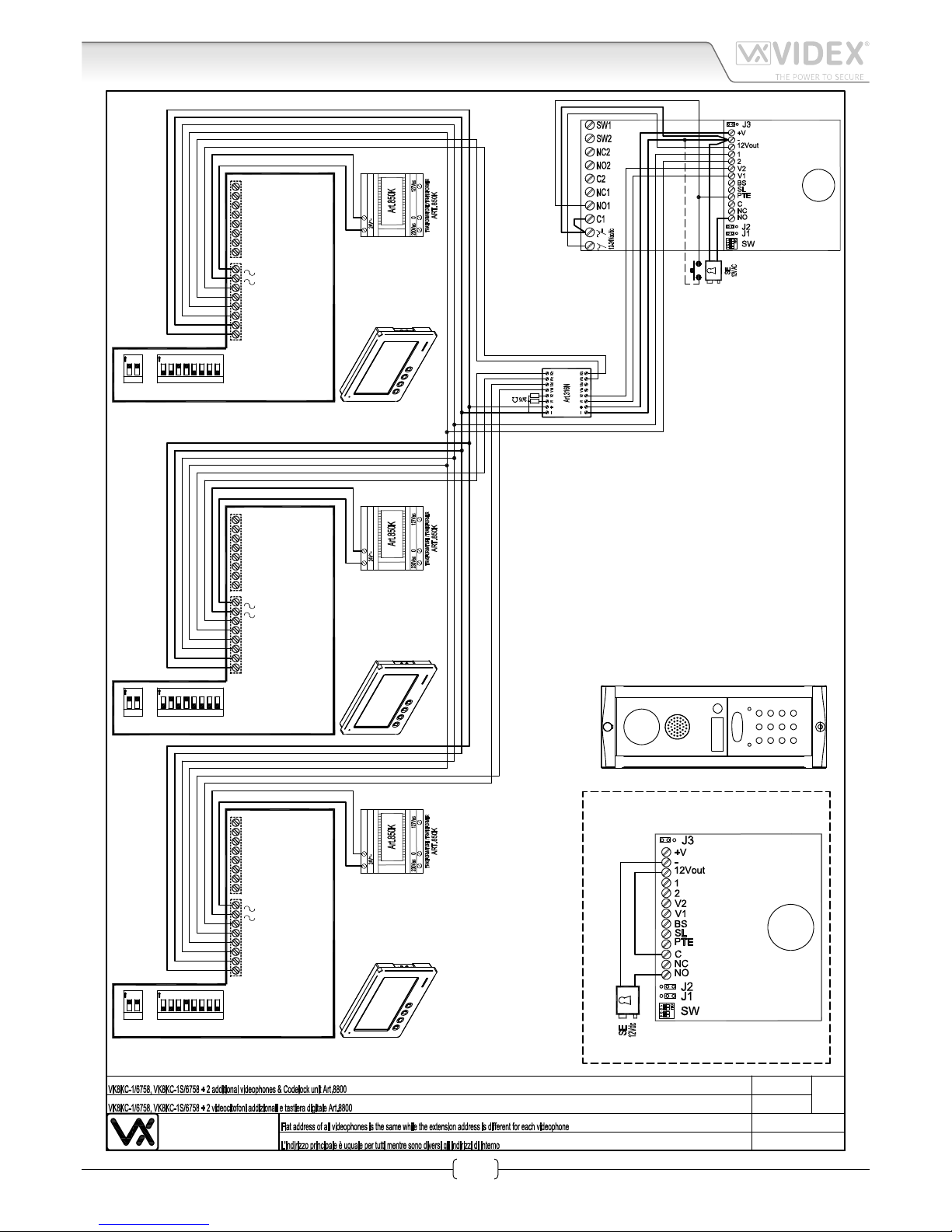
Art.6758 7" hands free colour display digital videomonitor
27mm
200mm
150mm
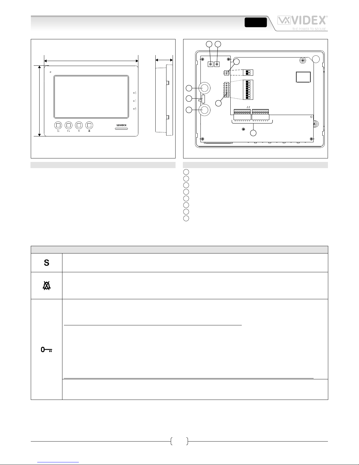
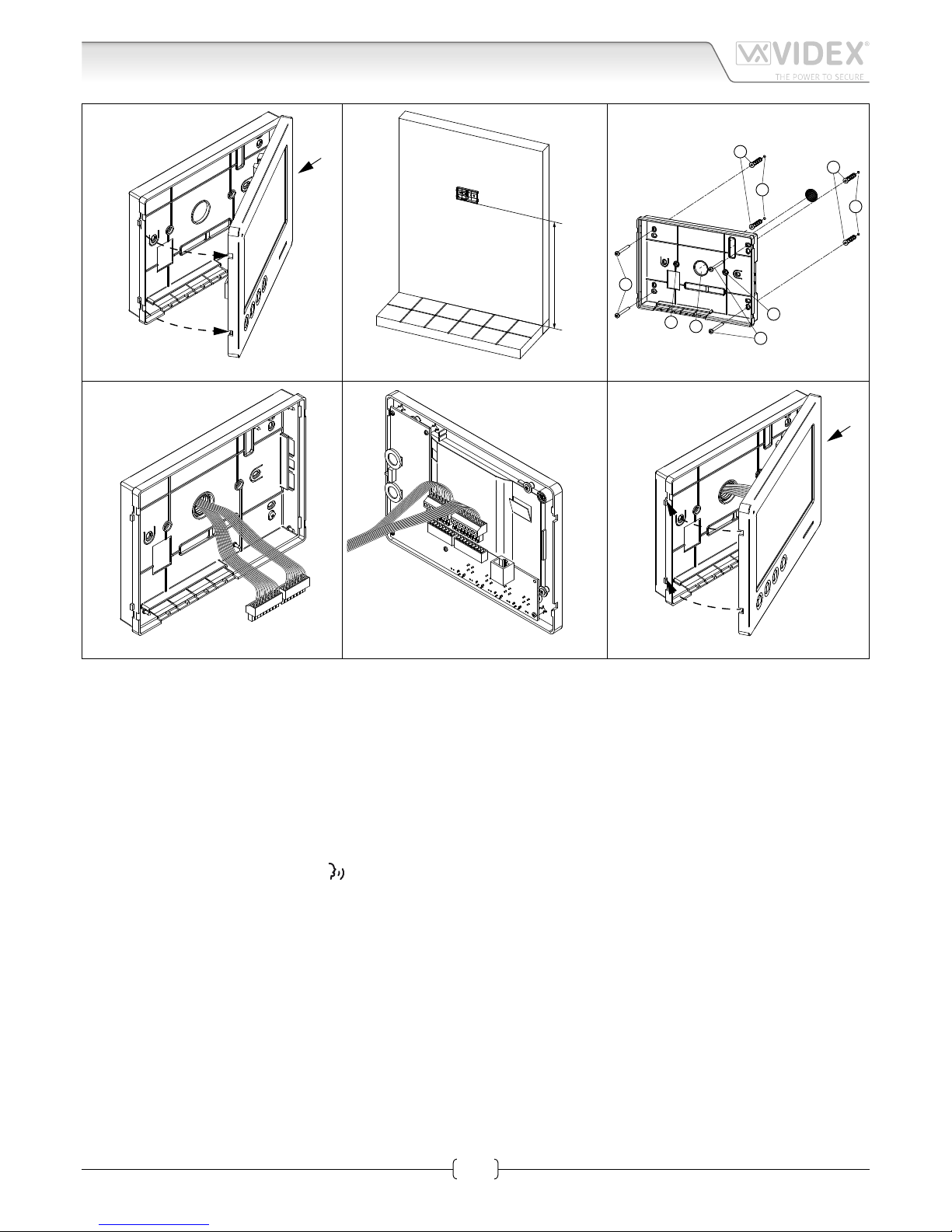
Fig. 1
PT2 PT3
PT1
SW1
VR1
6 7 8
1235
4
ON
DSW1
DSW2
12
ON
V2
V1
2
1
−
+V
4A
5A
12M
3A
2A
LD
SB
LB
A
B
C
H
G
F
D E
Fig. 2
DESCRIPTION
Surface mount hands free videophone incorporating a 7”Hi-Res
full colour active matrix LCD monitor specic for “6 wire” vid-
eokit (VK4K, VRVK and VK8K range). It includes 4 buttons: “cam-
era recall”“open door”“service” and “privacy”.
3 LED’s* indicate the privacy activated , open door and activat-
ed functions.
Programmable privacy duration and number of rings. Intercom-
municating call and door call.
Adjustments: call tone volume switch (3 levels), picture hue,
contrast and brightness.
* The operation of some LED’s and the functions described may require additional cabling.
LEGEND
AConnection terminals
B8 Way dip switch bank to set videophone address
C2 Way dip switch bank to set video mode
DHue adjustment trimmer
EContrast adjustment trimmer*
FSpeech volume control
GBrightness control
HCall tone volume switch
* Not available in some LCD versions.
PUSH BUTTONS FIG. 1
Service push button.
Shorts the “SB” terminal to GROUND (open collector 24Vdc 100mA max) while the button remain pressed.
Privacy ON-OFF button.
When the system is in stand-by, the pressing of this button activates (LED switched on) or disables (LED switched
o) the “privacy” service. The service is automatically disabled when the programmed privacy time expires. When
the service is enabled the videophone does not receive calls.
Door-open / intercommunicating call button.
With speech lines open to the entrance panel, press this button to open the door. If the terminal “LD” is properly
connected the relevant LED remains switched ON until the door is closed.
Intercommunication only works when the system is in the stand-by condition.
Switch 4 of the SW1 dip-switch selects the type of intercommunication:
OFF Intercommunication between two apartments - press the key button to call the videophone(s) in the other
apartment. A busy tone will signal that the other videophone is in conversation with the door station and so
cannot be called.
ON Intercommunication between videophones in the same apartment
- press the key button one, two, three or four times to call videophone with extension address 1, 2, 3 or 4 (Set on
dip-switches 2&3 of SW1).
Any intercommunicating conversation is always interrupted by an external call (i.e. External calls take priority).
Intercommunication push button.
For an intercommunicating call, press as many times as the extension or address value to call (see SW3 Intercommu-
nication Settings).
ENG