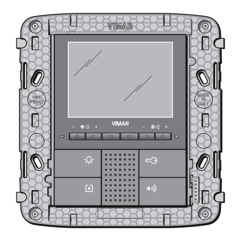
Vimar By-Me 21509 User manual

Control panel 21509
Instructions manual

1

2

3
Section
automation

4

5
Table of Contents
General information................................................................... 6
1. Main functions ................................................................... 7
2. Basic concepts................................................................... 8
3. Installation topology............................................................... 14
3.1 Installation of bus systems................................................................... 15
3.2 Description of terminals ..................................................................... 18
3.3 Putting the system into service ................................................................ 19
4. Main configurations . . . . . . . . . . . . . . . . . . . . . . . . . . . . . . . . . . . . . . . . . . . . . . . . . . . . . . . . . . . . . . . 20
4.1 Navigating the control unit menus ............................................................. 20
4.2 Initial switch-on ........................................................................... 21
4.3 Main screens of the control unit ............................................................... 23
4.4 Settings menu ............................................................................ 24
4.5 Configuration menu ........................................................................ 29
5. HVAC control .................................................................... 55
5.1 General settings........................................................................... 55
5.2 Operating modes.......................................................................... 63
5.3 Programming............................................................................. 65
6. Scenarios ....................................................................... 66
6.1 Creating a scenario . . . . . . . . . . . . . . . . . . . . . . . . . . . . . . . . . . . . . . . . . . . . . . . . . . . . . . . . . . . . . . . . . . . . . . . . . 66
6.2 Activating a scenario ........................................................................ 68
6.3 Renaming a scenario ....................................................................... 68
6.4 Deleting a scenario ........................................................................ 69
6.5 Cancelling a button associated with the scenario................................................... 69
6.6 Remote access to scenarios ................................................................. 69
7. Load control ..................................................................... 70
7.1 Functionality .............................................................................. 70
7.2 Power management ........................................................................ 71
7.3 Load management ......................................................................... 73
7.4 LED signals of the module 01855 .............................................................. 75
8. Programming events .............................................................. 76
8.1 Programming............................................................................. 76
8.2 Operation ............................................................................... 82
8.2 Example applications....................................................................... 83
9. Integration of the passive infrared presence detectors and the contacts interfaces ........... 87
10. Diagnostics and maintenance ...................................................... 88
10.1 Diagnostics and replacement of devices ........................................................ 88
10.2 Remote communications management ........................................................ 89
10.3 Control unit software release ................................................................. 89
11. Installation rules .................................................................. 90
12. Compliance with regulations ........................................................ 90
13. Supplementary declarations made by the manufacturer ................................. 90
6
General information
The By-me automated system via the control unit 21509 provides integrated control of comfort, security, energy
saving, HVAC and remote control in the residential and commercial sectors.
This manual is arranged in a sequence of sections that provide a complete understanding of the By-me system
and allow the user to take full advantage of the available features:
• Chapter 1 “Main functions”: describes what can be controlled with the By-me system (see page 7);
• Chapter 2 “Basic concepts”: explains some basic concepts necessary for gaining an understanding the By-
me system (see page 8);
• Chapter 3 “Installation topology”: describes the structure of the By-me system and gives the general rules
and information necessary for setting the system structure and the information necessary for putting into opera-
tion (see page 14);
• Chapter 4 “Main configurations”: describes the configuration procedures and main settings of the By-me
system (see page 21);
• Chapter 5 “HVAC control”: describes the procedures for setting the climate control programs (see page 55);
• Chapter 6 “Scenarios”: describes the procedures for creating scenarios where a number of functions are actu-
ated at the same time (see page 66);
• Chapter 7 “Load control”: describes the procedures for controlling the power drawn from the electric mains in
order to prevent the miniature circuit breaker tripping due to overloading (see page 70);
• Chapter 8 “Programming events”: describes the procedures for advanced management of the By-me system,
in order to be able to initiate functions that perform special operations when certain events occur (see page 76);
• Chapter 9 “Integration of the passive infrared presence detector”: describes the procedures for managing
detectors both as intrusion alarm sensors and motion sensors with lights coming on (see page 87).
• Chapter 10 “Diagnostics and maintenance”: describes the procedures for monitoring the operation of devices
and managing their replacement where necessary (see page 88);

7
Main functions:
1. Main functions.
The By-me system makes it possible to manage the installation using the following controls:
• Ambienttemperaturemanagement,dividingtheinstallationintoupto40areascontrolledby40separatepro-
grams;
• Lightingmanagement,withon/offcontrolandlightadjustment;
• Controlforrollershuttersandblinds;
• Functioncentralizationandautomation(upto32scenariosand16programs);
• Controloftheintrusiondetectionalarmsystem;
• Remotecontrolandmonitoringoffunctions;
• Powerconsumptionandloadcontrol.
• Speakersystemmanagement.
SAVINGS
Power management
Load programming
Temperature control
Control unit 21509
REMOTE CONTROL
Temperature status
Aircon programming
Alarm signals
Device actuation
Scenario activation
Intrusion detection alarm system
ON/OFF
Diagnostics
Scenarios
Light automation
Shutter automation
Temperature control
Programmed actions
Load control
Speaker system
COMFORT SECURITY
Wired burglar alarm system
Radio burglar alarm system
Remote assistance
Technical alarms
Panic alarm
Access control
emergency lighting
Main menu
Logout Setup
Climate
Temperature
Scenarios
Events Pro
g
ramme
Probe

8
Basic concepts
2. Basic concepts.
This chapter explains some fundamentally important concepts that are necessary for correctly making full use of
the system.
Note.
Some examples refer to the device codes; for further information please refer to the product's instructions sheet.
• Functional unit: part of a device that can be considered as if it were a separate device. Some examples:
1. Appliance with one functional unit: the functional unit is equivalent to the device itself, for example actuator
with change-over relay output 16 A 250 V~ (Eikon 20535; Idea 16975; Plana 14535 series).
2. Appliance with two functional units: in the interface for conventional controls (Eikon 20515 series; Idea 16955
series; Plana 14515 series) each of the two inputs is a functional unit.
3. Appliance with three functional units: in the control equipment with two rocker switches and actuator (Eikon
20526 series; Idea 16966 series; Plana 14526 series) there are three functional units: left rocker switch, right
rocker switch and actuator that, from the point of view of the configuration and operation, are to all intents
and purposes 3 different devices.
4. Appliance with four functional units: in the control equipment with three rocker switches and actuator (Eikon
20547 series; Idea 16987 series; Plana 14547 series) there are four functional units: left rocker switch, central
rocker switch, right rocker switch and actuator that, from the point of view of the configuration and operation,
are to all intents and purposes 4 different devices. Another example is the device with 4 changeover relays
(art.01851.2 for installation on DIN (60715 TH35) rails) where each output is a functional unit.
Note.
Difference between a rocker switch and a simple
switch: a rocker switch can be pushed up or down, a
simple push-button can only be pushed down.
During the design phase, each functional unit of
any device must be considered as though it were a
separate device. It is therefore necessary, during the
design phase, to plan the functions to be performed
and only then make a list of the devices needed to
perform these functions.
The diagram opposite shows the functional units of a
control device with three simple push-buttons and an
actuator (Eikon 20545 series; Idea 16985 series; Plana
14545 series).
For example, during installation, the actuator could be used to control load A through the push-button of another
device, the left push-button to control load B through an actuator, the middle button to control load C through a
second actuator and the right button to control load D through a third actuator.
Relay actuator Left
button
Right
button
Middle
button

9
Basic concepts
There are no limits on the use of the functional units of a physical device. When a load is to be controlled, it is
necessary to provide one control device and one actuator connected to the load.
• Connection: logic link between two functional units, which allows a function to be shared (for example: actuator
relay and push button).
Control appliance with three simple buttons and actuator
(Eikon 20545; Idea 16985; Plana 14545).
Front view Rear
ButtonActuatorActuator
Load C Load D Load A
Actuator
Load D

10
•Group depth: number of groups to which one functional unit can belong. Each functional unit can belong to a
maximum of 4 different groups keeping the same function (for example “dimmer control”).
• Scenario: a scenario is an exact positioning of the actuators in one or more functional groups that can be called
up as preferred from a menu on the control unit or with a button configured for this purpose or with the infrared
remote control 01849. For example, the rolling shutters could be lowered and a lamp lit in the room at the same
time. A scenario can also be activated with the programs that can be configured via the Events menu or remotely
with the GSM communicator or Web Server.
Basic concepts
Eikon 20521
Idea 16961
Plana 14521
Eikon 20535
Idea 16975
Plana 14535
BUS line
• Conguration: operation that can be used to create the logic connection between various functional units (of
various appliances).
• Functional group (or Group): set of functional units connected logically with each other that provide a function
in the system (for example: three different buttons that control a single actuator and, as a result, the same load).
The devices that make up a functional group are connected to each other logically, not by conventional wiring.
IMPORTANT:
Groups must comprise only functional units that are harmonious with each other: any one group cannot
contain an actuator for roller shutters and an actuator to control the lighting of a lamp.
Control equipment with
two rocker switches. Actuator with relay output.

11
Basic concepts
Eikon 20521
Idea 16961
Plana 14521
Eikon 20535
Idea 16975
Plana 14535
BUS line
Eikon 20521
Idea 16961
Plana 14521
• Parameters:thesecanbesetatthecontrolunit,andareusedtomodifyandcustomizetheoperationofeach
functional unit. For example, the relay actuator (Eikon 20535 series, Idea 16757 series; Plana 14535 series), dur-
ing configuration, behaves as a two-position stable relay. It is, however, possible to configure it as one-position
stable; in this case it is necessary to define the deactivation time too.
Eikon 20521
Idea 16961
Plana 14521
3
M
Eikon 20527
Idea 16967
Plana 14527
1
M
Eikon 20527
Idea 16967
Plana 14527
2
To control the switching on of a load from different points, it is sufficient to add more functional units; it is not neces-
sary to modify the wiring.
Group
1
= device 1: left button functional unit + device 1 actuator
Group
2
= device 2: left button functional unit + device 2 actuator
Group
3
= device 3: button functional unit + device 1 and 2 actuator functional unit
Actuators are of group depth 2 since they both belong to two groups.

12
Basic concepts
• Line: any set of devices.
• Scenario depth: number of scenarios to which a group can belong. Each functional group can belong to a
maximum of 4 different scenarios.
• Bus line: equipment used to carry the electrical or electromagnetic signals associated with the messages be-
tween the system devices.
• Bus system: set of devices and their interconnections creating applications by using a common communica-
tions framework.
• Command:functionalunitthatsendscommandsand/orstatusesoverthebusline.
•
Actuator:functionalunitthatreceivescommandsand/orstatusesfromthebuslineinordertocarryoutapre-
determined action.
The system in general is made up of three main families of functional unit:
•Controls(forexample,push-buttons,sensorsandinfraredremotecontrols)
•Actuators(forexample,relaysanddimmers)
•Controllers(forexample,thecontrolunit)
Each line can be composed of at most 128 devices and needs one or two power supplies depending on
the number of devices and the length of the bus.
Using line couplers, a number of lines can be connected to each other, up to a maximum of 15 areas by 15
lines; the line couplers allow only authorized messages to pass between one line and another.
On each By-me control unit it is possible to configure up to 254 devices (194 automation devices and 60
intrusion detection alarm system devices).
System configuration starts with the creation of functional groups (it is better to think in terms of functional
groups rather than individual devices), which is the only operation strictly necessary for the system to
function. During the installation phase, the first operation is therefore to assume the functions that are to
be made available.
Subsequent operations, such as placing a number of units together in one scenario or setting a number of auto-
matedfunctions,shouldbetreatedasasystemcustomizationorastheuseofadvancedfunctions.

13
From the moment the groups are created, the control unit has no role in their operation; the devices and related
functional groups are “connected” to each other and do not require any intervention by the control unit (the control
unit is still needed, however, for managing editing functions, HVAC automation and automation programmes).
In the event of a power failure, when the mains power returns, the actuators will keep their status prior to the event.
Following a Reset applied to an actuator, instead, the actuator will go back to opening the contact (applies both to
relay actuators and roller shutter actuators).
Note: If the By-me system is composed of both the automation system and the intrusion detection alarm system,
always use two power supplies 01801.
Basic concepts

14
230 V~
LN492.180120B 0409 VIMAR - Marostica - Italy
29 V BUS
AUX
01801
POWER SUPPLY UNIT
120-230V~ 50/60Hz
440-290mA
-5°C ÷ +45°C
BUS
AUX
29V
29V
BUS
AUX
I
I
BUS +
IAUX
I
VI
800mA
By-me
bus
L
N
M
230 V~
LN492.180120B 0409 VIMAR - Marostica - Italy
29 V BUS
AUX
01801
POWER SUPPLY UNIT
120-230V~ 50/60Hz
440-290mA
-5°C ÷ +45°C
BUS
AUX
29V
29V
BUS
AUX
I
I
BUS +
IAUX
I
VI
800mA
By-me
Main menu
Logout Setup
Climate
Temperature
Scenarios
Events Programme
Probe
Installation topology
3. Installation topology.
The main characteristic of the By-me system is that all devices are connected to each other by a bus system cable
(pair) that supplies the devices with the power and the signals carrying the digital control and monitoring data.
WARNING:
On a line where a control unit 21509 has already been configured it is not possible to configure a second
control unit (whether 21509, 21550-20550-14550 + 01960 or the 2-module control units Eikon 20510 and
20480, Idea 16950 and 16930, Plana 14510 and 14480).
The system is configured through the control unit and the configuration buttons located on the devices.
In the case of integration between the automation system and the intrusion detection alarm system, see
CONNECTION DIAGRAM with separation coupler from another automation line.
Controls
Control unit 21509
IR detector
Relay actuator Controls with
relay actuator
Controls with
roller shade
actuator
Power supply Line 1
Power supply Line 2
Line coupler
Controls

15
the intrusion detection alarm system section in this manual that gives the wiring diagram (see page 95); in this case
the control unit must be installed and configured in "Area 00 - Line 00" of the intrusion detection alarm
system. The two automation and intrusion detection alarm system lines must then be separated with a
coupler 01845.
The power consumption of the control unit is:
-45 mA of maximum instantaneous consumption with backlit display;
-25 mA with display without backlighting (Stand By);
3.1 Bus system installation.
3.1.1 General rules and system topology.
• FortheconnectionsusethetwistedpairandsheathedcableVIMAR01840(2x0.5mm2, rated voltage to
earth 400 V, suited for installation with Category I power cables). The wire pair distributes both the power
supply voltage (29 V d.c.) and the device control signals, and can be placed inside the same corrugated pipe
that carries the electrical mains cables.
• Abuslinemustbesuppliedby1or2powersupplies01801.
Each line can be controlled by a single control unit and can be composed of at most 128 devices and at
most two power supplies, depending on the number of devices and the length of the connecting cable (pair).
• Onecontrolunitcanmanageuptoatmost60intrusiondetectionalarmsystems.
• Ifasystemisbeinginstalledwithonlyonepowersupplyandthenumberofdevicesisclosetothemaximum
number allowed, it is advisable to plan for a second power supply to allow for future extensions of the sys-
tem.
• Thedevicesdonothavetobeconnectedinanyparticularorder,maintainingthepolaritiesindicatedonthe
terminals. Linear type connections (figure 3.1.1.1), star type connections (figure 3.1.1.2) or mixed connec-
tions (figure 3.1.1.3) are possible (the rectangle in the figures represents the power supply). The ideal con-
figuration is the linear type with only one power supply in the middle of the system, or two power supplies
at the ends of the bus cable.
• Thetotalcurrentusedbythevariousdevicesmustnotexceedthenominalcurrentofthepowersupply(or
supplies) installed.
• Thevoltageatallpointsonthebus,withalldevicesatrest,mustnevergobelow23Vd.c.Checkparticularly
the points furthest away from the power supply and the sections of cable where the load is highest.
• Thevoltageatallpointsonthebus,whenthemostnumerousgroupofshutteractuatorsisinoperation,
must never go below 22 V d.c. (check the points furthest away from the power supply). The delayed actua-
tion function can be useful for reducing the number of shutter actuators in operation at the same time.
• TheBy-mecontrolunitcanmanageupto20differentusers(includingtheadministrator),eachonewiththeir
own privileges and password.
• The By-me control unit can manage up to at most 480 groups (automation, intrusion detection alarm sys-
tem, loads, etc.).
Installation topology

16
Installation topology
• TheBy-mecontrolunitisabletocongureuptoatmost254devicesdividedoveranumberoflines(includ-
ing the couplers 01845); each device can have from 1 to 4 functional units. If the system does not have an
intrusion detection alarm system, the maximum number of Automation devices that can be configured on a
control unit is equal to 194 (including the routers) distributed over a number of lines; lastly, bear in mind that
one line can be installed with up to at most 2 power supplies 01801 (which can sustain up to a maximum
consumption of 1.6 A on the bus line).
• Itisessentialtoprotectthesystemfromtheeffectsoflightingusingsurgeprotectiondevices(SPD).
As a general rule, the power supply side must be protected using a Class 1 SPD downstream of the power
meter, a Class 2 SPD after the magneto-thermal protection device, and a Class 3 SPD at the power supply
input. If a telephone communicator is present, it is advisable also to install an SPD on the telephone line.
3.1.2 System setup.
During the design phase, it is essential to arrange for a consumer unit with sufficient capacity to hold:
• conventionaldevices,magneto-thermalprotections,circuit-breakers,etc;
• 1or2powersupplieswithcapacityfor9modulesonDIN(60715TH35)rails;
• DIN(60715TH35)raildevicessuchastheloadcontrolmodule,GSMcommunicator,interfaces,webserver.
• surgeprotectiondevicestoprotecttheinstallation.
As regards the corrugated pipes for laying the Vimar cable 01840 of the BUS line, it is advisable to plan
for a dedicated raceway; it is however possible to use those where the cables of the electric mains pass.
3.1.3 Bus length: general rules.
• Maximumdistancebetweenpowersupplyanddevice:350m.
• Maximumdistancebetweendevices:700m.
• Maximumlengthofthebuscable:1000m.
• Minimumdistancebetween2powersupplies:40m.Itisimportantfortheloadtobewelldistributedbe-
tween the two power supplies.
3.1.1.1
3.1.1.2
3.1.1.3

17
• Essentialrequirements:
• thedistancebetweentwopowersuppliesmustneverbelessthan40m;
• theloadmustbewelldistributedbetweenthetwopowersupplies;
• thetwopowersuppliesshouldbeplacedattheendsoftheoneofthecircuitsofthesystemthathas
the largest number of devices or branches.
In any case the optimal configuration has the power supplies set as far apart as possible; this has a positive
effect also on the minimum voltage on the bus.
3.1.4 Length of the BUS line.
The following is a list of the maximum lengths of the BUS line installed in systems with the linear configuration
(the rectangle in the figure represents the power supply).
Installation topology
350 m
POWER SUPPLY
350 m 350 m
700 m
250 m 250 m
POWER SUPPLY
DEVICE DEVICE
500 m
POWER SUPPLY POWER SUPPLY

18
Installation topology
3.1.5 Bus installation: summary table.
• Installation and system topology:
• CableoftheBUSlinelaidindedicatedraceways;itcanalsobelaidinthecorrugatedpipesthatcontain
the electric line.
• Congurationsallowed:
• Linearconguration
• Starconguration
• Mixedconguration
• Werecommendusingjunctionboxes
• For the connections use the twisted pair and sheathed cable VIMAR 01840 (2x0.5 mm2, rated
voltage to earth 400 V, suited for installation with Category I power cables)
• Devices and distances per line
• Logiccapacity(numberofaddresses):128
• Maximumdistancebetweenpowersupplyandlastdevice:350m
• Maximumtotallengthofthebusline:1,000m
• Maximumdistancebetweentwodevices:700m
• Minimum distance between two power supplies: 40 m (loads must be balanced between the two
power supplies)
• Optimalpositionforeachsinglepowersupply:inthecentreoftheBUSline
• Optimalpositionfortwopowersupplies:attheendsoftheBUSline
• Minimumvoltageonthefurthestdevice:23Vd.c.(atrest)
3.2 Terminals of the control unit.
The back of the control unit 21509 has (fig. 3.3.1):
- TP bus terminals;
- temperature sensor terminals;
- PIN-STRIP 8-pin connector for the cable that enables connecting the programming interface
01998.U.
•TerminalsBUS+andBUS-mustbeconnectedtotheBUS+-outputofthepowersupply01801.
•IfthereisalsotheintrusiondetectionalarmsystemtheBUS+andBUS-terminalsmustbeconnectedtothe
BUS + - output of the back-up unit 01804.
•Maximumlengthoftheconnectingcableoftheexternalprobe::60m.
Use a twisted cable with a minimum cross-section of 0.5 mm2(art. 01840).

19
3.3 Putting the system into service.
To install the devices correctly, carry out the following operations:
1. Lay out the bus cable and connecting terminals, maintaining the correct polarities (figure 3.4.1).
2. Lay out the cable for the electrical connections of the actuators.
3. Wire the control unit, components and power supply.
4. Power up the system.
Installation topology
TP BUS
terminals
3.3.1
PIN-STRIP 8-pin
connector for 01998.U
Temperature sensor terminals
3.4.1
Connection terminal
Vimar 01840 twisted pair
This manual suits for next models
1
Table of contents
Other Vimar Control Panel manuals

Vimar
Vimar 1960 User manual

Vimar
Vimar ELVOX SW24.W User guide

Vimar
Vimar ELVOX RS11 User manual

Vimar
Vimar By-alarm 01700 User guide

Vimar
Vimar Elvox RS10 User manual

Vimar
Vimar By-alarm 01700.DE User manual

Vimar
Vimar ELVOX 13C5 Assembly instructions

Vimar
Vimar Elvox SW24.D User guide

Vimar
Vimar Eikon Evo 21512.1 User manual

Vimar
Vimar By-alarm 01700 User guide
Popular Control Panel manuals by other brands

GESTRA
GESTRA SPECTORcontrol user manual

FBII
FBII XL-2S Silver Hookup and installation instructions

GE
GE Concord express instruction manual

Protect America
Protect America Simon XT installation manual

Freedom Scientific
Freedom Scientific TOPAZ PHD Reference card

Assa Abloy
Assa Abloy effeff 925 installation manual