manuals.online logo
Brands
  1. Home
  2. •
  3. Brands
  4. •
  5. Vimar
  6. •
  7. Security System
  8. •
  9. Vimar Elvox ELA5 User manual

Vimar Elvox ELA5 User manual

ELA5, ELA6, ELA7
Viale Vicenza, 14
36063 Marostica VI - Italy
www.vimar.com
S6I.ELA.500 05 1909
EL33
Fig./Abb./Εικ. 1
Fig./Abb./Εικ. 2
12/24 Vdc
3 4 5 6
120/230 Vac
1 2 5 6
120/230
Vac
1 2 5 6
12/24
Vdc
3 4
12/24 Vdc
120/230 Vac
JP1
JP2
Fix
Flash
JP2
Fix
Flash
Fig./Abb./Εικ. 3
ELA5
12/24 Vdc
3 4 5 6
120/230 Vac
1 2 5 6
120/230
Vac
1 2 5 6
12/24
Vdc
3 4
12/24 Vdc
120/230 Vac
JP1
JP2
Fix
Flash
JP2
Fix
Flash
Fig./Abb./Εικ. 4
ELA6
12/24 Vdc
3 4 5 6
120/230 Vac
1 2 5 6
120/230
Vac
1 2 5 6
12/24
Vdc
3 4
12/24 Vdc
120/230 Vac
JP1
JP2
Fix
Flash
JP2
Fix
Flash
Fig./Abb./Εικ. 5
ELA7
ELA5, ELA6, ELA7
Viale Vicenza, 14
36063 Marostica VI - Italy
www.vimar.com
S6I.ELA.500 05 1909
Descrizione prodotto
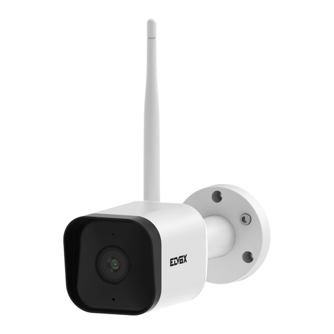
ELA5, ELA6, ELA7 è una linea di lampeggianti per l’automazione
di cancelli e porte da garage con LED ad alta efficienza e antenna
accordata a 433 MHz.
Modello Descrizione
ELA5 Lampeggiante a LED con alimentazione12/24 Vdc,
antenna integrata, lampeggio comandato dalla centrale
ELA6
Lampeggiante a LED con alimentazione 120/230 Vac,
antenna integrata, lampeggio integrato su lampeggian-
te o comandato dalla centrale selezionabile mediante
jumper JP2
ELA7
Lampeggiante a LED con selezione alimentazione
12/24 Vdc o 120/230 Vac, antenna integrata, lam-
peggio integrato su lampeggiante o comandato dalla
centrale selezionabile mediante jumper JP2
Precauzioni e avvertenze
L’installazione del prodotto deve essere effettuata da personale
qualificato, nel rispetto delle leggi e norme vigenti nel territorio.
Prima di effettuare i collegamenti elettrici del lampeggiante togliere
l’alimentazione alla centrale di comando e disconnettere le batterie
se presenti. Verificare che la tensione di uscita lampeggiante della
centrale sia corrispondente alla tensione di alimentazione del lam-
peggiante stesso.
Verifiche prima dell’installazione
- verificare che la posizione prescelta garantisca all’utente una
buona visibilità del lampeggiante.
Installazione del lampeggiante
- Inserire il cavo di alimentazione ed eventualmente il cavo antenna
nell’apposito foro e assicurarli con le fascette fornite come indicato
in fig. 1.
- Fissare il fondo del lampeggiante su una superficie piana orizzon-
tale in un punto ben visibile all’utilizzatore
- Nel caso sia necessario posizionare il lampeggiante a parete
utilizzare il supporto opzionale EL33 (fig. 2) avvitandolo con le 2
viti fornite.
Collegamenti elettrici
ELA5: vedere fig. 3, ELA6: vedere fig. 4, ELA7: vedere fig. 5.
Caratteristiche tecniche:
Modello ELA5 ELA6 ELA7
Alimentazione 12/24 Vdc 120/230 Vac 12/24 Vdc
Assorbimento 250 mA 12 mA 250 mA 12/24 Vdc
12 mA 120/230 Vac
Grado di
protezione IP54 IP54 IP54
Temperatura
di utilizzo -20 °C
+55 °C
-20 °C
+55 °C
-20 °C
+55 °C
Jumper JP1 - - Selezione alimenta-
zione 12/24 Vdc o
120/230 Vac
Jumper JP2 -
Selezione
lampeggio
integrato su
lampeggiante
o su centrale
di comando
Selezione lam-
peggio integrato
su lampeggiante
o su centrale di
comando
Product description
ELA5, ELA6, ELA7 is a line of flashing lights for the automation
systems of gates and garage doors with high-efficiency LED and
aerial tuned to 433 MHz.
Model Description
ELA5 12/24 Vdc LED flashing light with built-in aerial and
control panel controlled flashing
ELA6 120/230 Vac LED flashing light with built-in aerial and
selectable integrated flashing or control panel con-
trolled flashing through jumper JP2
ELA7
LED flashing light with 12/24 Vdc or 120/230 Vac
power supply selection, built-in aerial and selectable
integrated flashing or control panel controlled flashing
through jumper JP2
Precautions and Warnings
The product must be installed by qualified personnel in compliance
with the current laws and regulations of the territory. Before making
the electrical connections for the flashing light, cut off the power to
the control panel and disconnect the batteries, when present. Check
that the flashing light output voltage from the control panel matches
the supply voltage of the flashing light.
Checks prior to installation
- check that the chosen position ensures the user has a clear view
of the flashing light.
Installing the flashing light
- Insert the power cord into the socket and and possibly the aerial
cable through the hole and secure them with the cable ties sup-
plied as shown in Fig. 1.
- Secure the base of the flashing light on a flat horizontal surface in
a clearly visible position for the user.
- If a wall-mount installation is needed, use the optional support
EL33 (Fig. 2) , securing it with the 2 provided screws.
Electrical connections
ELA5: see fig. 3, ELA6: see fig. 4, ELA7: see fig. 5.
Technical data:
Model ELA5 ELA6 ELA7
Power supply 12/24 Vdc 120/230 Vac 12/24 Vdc
Absorption 250 mA 12 mA 250 mA 12/24 Vdc
12 mA 120/230 Vac
Degree of
protection IP54 IP54 IP54
Operating
temperature -20°C
+55°C -20°C +55°C -20°C +55°C
Jumper JP1 - - Power supply
selection 12/24 Vdc
or 120/230 Vac
Jumper JP2 -
Integrated or
control panel
controlled
flashing
selection
Integrated or control
panel controlled
flashing selection
ELA5, ELA6, ELA7
Viale Vicenza, 14
36063 Marostica VI - Italy
www.vimar.com
S6I.ELA.500 05 1909
Description de l'appareil
ELA5, ELA6, ELA7 est une ligne de clignotants pour l'automatisation
des portails et des portes de garage avec led à haute efficacité et
antenne syntonisée sur 433 MHz.
Modèle Description
ELA5 Clignotant à led, alimentation 12/24 Vcc, antenne
incorporée, clignotement commandé par la centrale.
ELA6
Clignotant à led, alimentation 120/230 Vca, antenne
incorporée, clignotement incorporé au clignotant ou
commandé par la centrale, sélectionnable via jumper
JP2.
ELA7
Clignotant à led avec sélection de l'alimentation 12/24
Vcc ou 120/230 Vca, antenne incorporée, clignote-
ment incorporé au clignotant ou commandé par la
centrale, sélectionnable via jumper JP2.
Précautions et avertissements
L'installation de l'appareil doit être confiée à un technicien qualifié,
conformément à la législation et aux normes locales en vigueur.
Avant d'exécuter les branchements électriques du clignotant, cou-
per l'alimentation de la centrale de commande et déconnecter les
batteries. Vérifier si la tension de sortie du clignotant de la centrale
correspond à la tension d'alimentation du clignotant.
Vérifier avant l'installation
- si la position sélectionnée permet à l'utilisateur de bien voir le
clignotant.
Installation du clignotant
- Faire passer le cordon d'alimentation et éventuellement le câble de
l'antenne à travers l'orifice et les fixer à l'aide des colliers fournis,
comme le montre la fig. 1
- Fixer la base du clignotant sur une surface plane horizontale, à
un endroit où il est bien visible pour l'utilisateur.
- S'il s'avère nécessaire de fixer le clignotant au mur, utiliser le
support en option EL33 (fig. 2), en le fixant avec les 2 visses
fournies.
Branchements électriques
ELA5 : voir fig. 3, ELA6 : voir fig. 4, ELA7 : voir fig. 5.
Caractéristiques techniques
Modèle ELA5 ELA6 ELA7
Alimentation 12/24 Vcc 120/230 Vca 12/24 Vcc
Absorption 250 mA 12 mA 250 mA 12/24 Vcc
12 mA 120/230 Vca
Indice de
protection IP54 IP54 IP54
Température
de service -20 °C
+55 °C
-20 °C
+55 °C
-20 °C
+55 °C
Jumper JP1 - - Sélection alimenta-
tion : 12/24 Vcc ou
120/230 Vca
Jumper JP2 -
Sélection du
clignotement
intégrée au
clignotant ou
à la centrale
de commande
Sélection du cligno-
tement intégrée au
clignotant ou à la
centrale de com-
mande
Descripción del producto
ELA5, ELA6, ELA7 es una línea de luces rotativas para la automa-
tización de cancelas y puertas de garaje con LED a alta eficiencia y
antena calibrada a 433 MHz.
Modelo Descripción
ELA5 Luz rotativa de LED con alimentación 12/24 Vcc,
antena integrada, parpadeo controlado por la central
ELA6
Luz rotativa de LED con alimentación 120/230 Vca,
antena integrada, parpadeo integrado en la propia luz
o controlado por la central, seleccionable mediante
el puente JP2
ELA7
Luz rotativa de LED con selección de alimentación
12/24 Vcc o 120/230 Vca, antena integrada, parpadeo
integrado en la propia luz o controlado por la central,
seleccionable mediante el puente JP2
Precauciones y advertencias
La instalación del producto debe ser realizada por personal cualifi-
cado, cumpliendo las leyes y normas vigentes en el territorio. Antes
de realizar las conexiones eléctricas de la luz rotativa, desconecte
la alimentación de la central de mando y las baterías, si las hay.
Compruebe que la tensión de salida para la luz rotativa de la cen-
tral se corresponda a la tensión de alimentación de la luz rotativa.
Comprobaciones antes del montaje
- Compruebe que la posición elegida garantice al usuario una
buena visibilidad de la luz rotativa.
Montaje de la luz intermittente
- Introduzca el cable de alimentación y, si fuera preciso, el cable
de la antena en el orificio correspondiente y sujételos con las
abrazaderas suministradas, como se indica en la fig. 1.
- Fije el fondo de la luz rotativa sobre una superficie horizontal
nivelada, en un lugar bien visible para el usuario.
- Si fuera necesario sujetar la luz rotativa a una pared, utilice el
soporte opcional EL33 (fig. 2) , fijándolo con los 2 tornillos sumi-
nistrados.
Conexiones eléctricas
ELA5: véase fig. 3, ELA6: véase fig. 4, ELA7: véase fig. 5
Características técnicas:
Modelo ELA5 ELA6 ELA7
Alimentación 12/24 Vcc 120/230 Vca 12/24 Vcc
Absorción 250 mA 12 mA 250 mA 12/24 Vcc
12 mA 120/230 Vca
Grado de
protección IP54 IP54 IP54
Temperatura
de utilización -20 °C
+55 °C
-20 °C
+55 °C
-20 °C
+55 °C
Puente JP1 - - Selección alimen-
tación 12/24 Vcc,
120/230 Vca
Puente JP2 -
Selección
del parpadeo
integrado en
la luz rotativa
o en la central
de mando
Selección del
parpadeo integrado
en la luz rotativa
o en la central de
mando
ELA5, ELA6, ELA7
Viale Vicenza, 14
36063 Marostica VI - Italy
www.vimar.com
S6I.ELA.500 05 1909
Produktbeschreibung
ELA5, ELA6, ELA7 ist eine Serie von Blinkleuchten für die
Automation von Toren und Garagentoren mit hoch effizienter LED
und abgestimmter 433 MHz Antenne.
Modell Beschreibung
ELA5 LED-Blinkleuchte mit 12/24 Vdc Versorgungsspannung,
eingebauter Antenne und über Steuergerät geschalteter
Blinkfunktion
ELA6
LED-Blinkleuchte mit 120/230 Vac
Versorgungsspannung, eingebauter Antenne und mit-
tels Jumper JP2 zwischen in der Blinkleuchte integ-
rierter oder über Steuergerät geschalteter Blinkfunktion
ELA7
LED-Blinkleuchte mit 12/24 Vdc oder 120/230
Versorgungsauswahl, eingebauter Antenne und mittels
Jumper JP2 zwischen in der Blinkleuchte integrierter
oder über Steuergerät geschalteter Blinkfunktion
Vorsichtsmaßnahmen und Hinweise
Die Installation des Produkts hat durch Fachpersonal gemäß den
im Installationsland geltenden Gesetzen und Normen zu erfolgen.
Vor dem Stromanschluss der Blinkleuchte die Versorgung zum
Steuergerät unterbrechen und etwaige Batterien trennen. Sicher-
stellen, dass die Blinkleuchten-Ausgangsspannung des Steuerge-
räts der Versorgungsspannung der Blinkleuchte entspricht.
Kontrollen vor der Installation
- Sicherstellen, dass der für die Installation gewählte Standort eine
einwandfreie Sicht der Blinkleuchte garantiert.
Installation der Blinkleuchte
- Das Versorgungskabel und gegebenenfalls das Antennenkabel in
die entsprechende Bohrung einführen und mit den mitgelieferten
Bindern gemäß Abb. 1 sichern.
- Die Bodenseite der Blinkleuchte auf einer ebenen und waagrech-
ten Oberfläche an einer sichtbaren Stelle befestigen.
- Zur Wandinstallation der Blinkleuchte den optionalen Halter EL33
(Abb. 2) verwenden und den Schrauben verwenden.
Elektrische Anschlüsse
ELA5: siehe Abb. 3, ELA6: siehe Abb. 4, ELA7: siehe Abb. 5.
Technische Merkmale:
Modell ELA5 ELA6 ELA7
Versorgung 12/24 Vdc 120/230 Vac 12/24 Vdc
Stromaufnahme 250 mA 12 mA 250 mA 12/24 Vdc
12 mA 120/230 Vac
Schutzart IP54 IP54 IP54
Betriebs-
temperatur -20 °C
+55 °C
-20 °C
+55 °C
-20 °C
+55 °C
Jumper JP1 - - Versorgungs-
auswahl 12/24 Vdc
oder 120/230 Vac
Jumper JP2 -
Anwahl der
Blinkfunktion
auf
Blinkleuchte
integriert
oder per
Steuergerät
Anwahl der
Blinkfunktion
auf Blinkleuchte
integriert oder per
Steuergerät
Περιγραφή προϊόντος
Η σειρά ELA5, ELA6, ELA7 είναι μια σειρά φλας για αυτοματισμούς
σε καγκελόπορτες και πόρτες γκαράζ με LED υψηλής απόδοσης και
κεραία συντονισμένη στα 433 MHz.
Μοντέλο Περιγραφή
ELA5 Φλας με LED και τροφοδοσία12/24 Vdc, ενσωματωμένη
κεραία, αναλαμπή ελεγχόμενη από την κεντρική μονάδα
ELA6
Φλας με LED και τροφοδοσία 120/230 Vdc, ενσωμα-
τωμένη κεραία, αναλαμπή ενσωματωμένη στο φλας ή
ελεγχόμενη από την κεντρική μονάδα με δυνατότητα
επιλογής μέσω βραχυκυκλωτήρων JP2
ELA7
Φλας με LED και επιλογή τροφοδοσίας 12/24 Vdc ή
120/230 Vac, ενσωματωμένη κεραία, αναλαμπή ενσω-
ματωμένη στο φλας ή ελεγχόμενη από την κεντρική
μονάδα με δυνατότητα επιλογής μέσω βραχυκυκλω-
τήρων JP2
Προφυλάξεις και προειδοποιήσεις
Η εγκατάσταση του προϊόντος πρέπει να πραγματοποιείται από
εξειδικευμένο προσωπικό, σύμφωνα με τους ισχύοντες νόμους και
κανονισμούς της περιοχής. Πριν από την πραγματοποίηση των
ηλεκτρικών συνδέσεων του φλας, διακόψτε την τροφοδοσία της
κεντρικής μονάδας ελέγχου και αποσυνδέστε τις μπαταρίες, εάν
υπάρχουν. Βεβαιωθείτε ότι η τάση εξόδου του φλας της κεντρικής
μονάδας αντιστοιχεί στην τάση τροφοδοσίας του ίδιου του φλας.
Έλεγχοι πριν από την εγκατάσταση
- Βεβαιωθείτε ότι η προεπιλεγμένη θέση διασφαλίζει ότι ο χρήστης
θα έχει καλή ορατότητα του φλας.
Εγκατάσταση του φλας
- Τοποθετήστε το καλώδιο τροφοδοσίας και ενδεχομένως το
καλώδιο της κεραίας στην ειδική οπή και ασφαλίστε τα με τους
παρεχόμενους σφιγκτήρες, όπως φαίνεται στην εικ. 1.
- Στερεώστε το κάτω μέρος του φλας σε επίπεδη και οριζόντια
επιφάνεια, σε ορατό σημείο από τον χρήστη.
- Στην περίπτωση που απαιτείται επιτοίχια τοποθέτηση του φλας,
χρησιμοποιήστε το προαιρετικό στήριγμα EL33 (εικ. 2) και οι βίδες.
Ηλεκτρικές συνδέσεις
ELA5: βλ. εικ. 3, ELA6: βλ. εικ. 4, ELA7: βλ. εικ. 5.
Τεχνικά χαρακτηριστικά:
Μοντέλο ELA5 ELA6 ELA7
Τροφοδοσία 12/24 Vdc 120/230 Vac 12/24 Vdc
Απορρόφηση 250 mA 12 mA 250 mA 12/24 Vdc
12 mA 120/230 Vac
Βαθμός
προστασίας IP54 IP54 IP54
Θερμοκρασία
χρήσης
-20°C
+55°C
-20°C
+55°C
-20°C
+55°C
Βραχυκυκλ-
ωτήρας JP1 - - Επιλογή τροφο-
δοσίας 12/24 Vdc ή
120/230 Vac
Βραχυκυκλ-
ωτήρας JP2 -
Επιλογή
αναλαμπής
ενσωματωμένης
στο φλας ή στην
κεντρική μονάδα
ελέγχου
Επιλογή αναλαμπής
ενσωματωμένης
στο φλας ή στην
κεντρική μονάδα
ελέγχου

This manual suits for next models

2

Other Vimar Security System manuals

Vimar BY-ALARM PLUS User manual

Vimar

Vimar BY-ALARM PLUS User manual

Vimar BY-ALARM PLUS User manual

Vimar

Vimar BY-ALARM PLUS User manual

Vimar Elvox ZSEM User manual

Vimar

Vimar Elvox ZSEM User manual

Vimar 0K03800.02 User guide

Vimar

Vimar 0K03800.02 User guide

Vimar BY-ALARM PLUS User manual

Vimar

Vimar BY-ALARM PLUS User manual

Vimar by-me Eikon Series User manual

Vimar

Vimar by-me Eikon Series User manual

Vimar BY-ALARM PLUS User guide

Vimar

Vimar BY-ALARM PLUS User guide

Vimar 0K03801.02 User manual

Vimar

Vimar 0K03801.02 User manual

Vimar ELVOX 46936.001 User manual

Vimar

Vimar ELVOX 46936.001 User manual

Vimar 62IF User manual

Vimar

Vimar 62IF User manual

Vimar 46KIT.436WF User manual

Vimar

Vimar 46KIT.436WF User manual

Vimar BY-ALARM PLUS User manual

Vimar

Vimar BY-ALARM PLUS User manual

Vimar By-alarm 01715 User manual

Vimar

Vimar By-alarm 01715 User manual

Vimar BY-ALARM PLUS User manual

Vimar

Vimar BY-ALARM PLUS User manual

Vimar BY-ALARM PLUS User manual

Vimar

Vimar BY-ALARM PLUS User manual

Vimar BY-ALARM PLUS User manual

Vimar

Vimar BY-ALARM PLUS User manual

Vimar BY-ALARM PLUS User manual

Vimar

Vimar BY-ALARM PLUS User manual

Vimar 46KIT.036C User manual

Vimar

Vimar 46KIT.036C User manual

Vimar ELVOX TVCC User manual

Vimar

Vimar ELVOX TVCC User manual

Vimar BY-ALARM PLUS User manual

Vimar

Vimar BY-ALARM PLUS User manual

Vimar BY-ALARM PLUS User manual

Vimar

Vimar BY-ALARM PLUS User manual

Vimar BY-ALARM PLUS User guide

Vimar

Vimar BY-ALARM PLUS User guide

Vimar By-alarm 01703.DE User manual

Vimar

Vimar By-alarm 01703.DE User manual

Vimar 6260.16P.02 Assembly instructions

Vimar

Vimar 6260.16P.02 Assembly instructions

Popular Security System manuals by other brands

ring Outdoor Siren manual

ring

ring Outdoor Siren manual

X10 UX23A owner's manual

X10

X10 UX23A owner's manual

DSC Power 832 installation manual

DSC

DSC Power 832 installation manual

NTI ENVIROMUX-SRN-MTR-xxxV  Series Installation instruction

NTI

NTI ENVIROMUX-SRN-MTR-xxxV Series Installation instruction

Blue Glass Electronics BGE-5742 Installation and operating instructions

Blue Glass Electronics

Blue Glass Electronics BGE-5742 Installation and operating instructions

alerta AUAM instruction manual

alerta

alerta AUAM instruction manual

E2S APPELLO A121AX instruction manual

E2S

E2S APPELLO A121AX instruction manual

Lexing lx-hs06 Instruction

Lexing

Lexing lx-hs06 Instruction

Carlon RC2235 Instruction guide

Carlon

Carlon RC2235 Instruction guide

Jasco 45245 user manual

Jasco

Jasco 45245 user manual

Stahl YL6 Series operating instructions

Stahl

Stahl YL6 Series operating instructions

Mircom flexnet Installation and operation manual

Mircom

Mircom flexnet Installation and operation manual

Samsung ADT Security Hub user guide

Samsung

Samsung ADT Security Hub user guide

Adesys Octalarm-IP user manual

Adesys

Adesys Octalarm-IP user manual

Bosch FMC-210-SM installation manual

Bosch

Bosch FMC-210-SM installation manual

Radionics Security System user guide

Radionics

Radionics Security System user guide

Ikegami MAXI-VIEW III Operating instructions manual

Ikegami

Ikegami MAXI-VIEW III Operating instructions manual

Patrol Hawk 2AKOIPHGW user manual

Patrol Hawk

Patrol Hawk 2AKOIPHGW user manual

manuals.online logo
manuals.online logoBrands
  • About & Mission
  • Contact us
  • Privacy Policy
  • Terms and Conditions

Copyright 2025 Manuals.Online. All Rights Reserved.