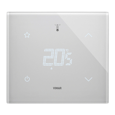
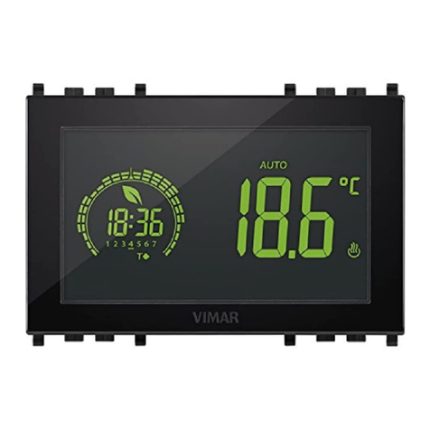
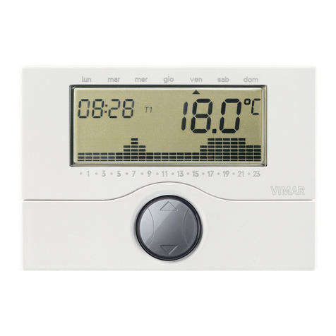
Vimar 2911 User guide

Instructions manual
02911 WiFi Timer-Thermostat
Installer Manual


1
Table of Contents
1. Timer-Thermostat 02911 ………………………………………………………………………………………… 3
2. Field of application ……………………………………………………………………………………………… 3
3. Installation ………………………………………………………………………………………………………… 3
4. Connections………………………………………………………………………………………………………… 4
4.1 Relay connection ……………………………………………………………………………………………… 4
4.2 External temperature probe …………………………………………………………………………………… 6
5. Switching on a resetting parameters…………………………………………………………………………… 8
6. Configuration via WiFi interface ………………………………………………………………………………… 9
6.1 First configuration ……………………………………………………………………………………………… 9
6.2 Configuring the temperature control parameters and using the device ……………………………… 15
6.3 Configuring the WiFi network and cloud services ………………………………………………………… 15
6.4 Pairing additional mobile devices with the timer-thermostat …………………………………………… 17
7. Display …………………………………………………………………………………………………………… 18
7.1 Functions of the buttons …………………………………………………………………………………… 19
7.2 Symbols ……………………………………………………………………………………………………… 19
7.3 Standby ……………………………………………………………………………………………………… 20
7.4 Locking the interface via PIN ……………………………………………………………………………… 20
7.5 Viewing the display ………………………………………………………………………………………… 21
8. Operating mode ………………………………………………………………………………………………… 22
8.1 Switched off (OFF) ………………………………………………………………………………………… 22
8.2 Manual………………………………………………………………………………………………………… 23
8.3 Auto…………………………………………………………………………………………………………… 24
8.4 Timed manual………………………………………………………………………………………………… 24
8.5 Away ………………………………………………………………………………………………………… 26
8.6 Antifreeze …………………………………………………………………………………………………… 27
9. Settings menu …………………………………………………………………………………………………… 27
9.1 Operating mode setting …………………………………………………………………………………… 28
9.2 Setting the time and day of the week ……………………………………………………………………… 28
9.3 Heating/air-conditioning setting …………………………………………………………………………… 28
9.4 Temperature setting ………………………………………………………………………………………… 29
9.5 Daily program setting ……………………………………………………………………………………… 29
9.6 Unit of measurement setting ……………………………………………………………………………… 30
9.7 Calibration setting …………………………………………………………………………………………… 32
9.8 External probe setting ……………………………………………………………………………………… 32
9.9 OnOff/PID temperature control algorithm setting ………………………………………………………… 33
9.10 Buzzer (beep) setting ……………………………………………………………………………………… 33
9.11 Standby brightness level setting ………………………………………………………………………… 34
9.12 WiFi setting ………………………………………………………………………………………………… 34
9.13 Info about the device ……………………………………………………………………………………… 36
9.14 Lock/unlock PIN setting …………………………………………………………………………………… 36
10. Parameters table ……………………………………………………………………………………………… 36
11. Configuring and checking alarms…………………………………………………………………………… 38
11.1 Temperatures and control conditions on the regulated temperature ………………………………… 38
11.2 Temperatures and control conditions on the temperature of the auxiliary probe …………………… 38
11.3 Limitation alarm ……………………………………………………………………………………………… 39
12. Warnings ……………………………………………………………………………………………………… 39
13. Cleaning the device …………………………………………………………………………………………… 39
14. Installation rules ……………………………………………………………………………………………… 40
15. Regulatory compliance ……………………………………………………………………………………… 40
16. Glossary: names and meaning of network and WiFi parameters……………………………………… 40
17. Appendix 1 - Data on the WiFi network …………………………………………………………………… 41
2
VIMAR S.p.A., as required by Italian Legislative Decree no. 196/2003, is authorized to manage the information
needed to perform the services described below, when registering the device on the Cloud servers of Vimar S.p.A.
The software platform of the Cloud servers of Vimar S.p.A. collects information from the device that is needed to
perform the services relating to the registered devices: the device ID, application version and the services provided
by it, the device configuration, as well as the pairing between the device and the authorized applications for the
remote control function, as well as signals for verifying correct access and operation of these services and devic-
es. The above information is all necessary and functional in order to enable correctly performing the functions of
remote control and maintenance of the applications and devices supported by the platform.
The ID of the device and the rest of the information are automatically recorded on the Cloud servers of Vimar S.p.A.
after WiFi configuration and access to the Internet. Users can disable the services that provide remote access to
their device, thereby deleting all the data relating to their device from the Vimar S.p.A. Cloud.

3
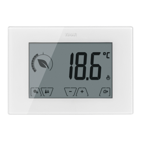
1. Timer-Thermostat 02911
WiFi timer-thermostat (802.11 b/g/n, 2.4GHz), wall-mounting, mains-powered (230 V~), with interface with
capacitive keys and equipped with user-friendly functions to facilitate energy saving.
Designed to control heating and air-conditioning via C, NC, NO relay output.
Equipped with an input for an external temperature sensor (not supplied) that can be used for monitoring,
control or limitation. Built-in buzzer.
WiFi connectivity lets you control/consult the device remotely, directly from your smartphone or tablet.
2. Field of application
The appliance is designed to control room temperature by acting on the control circuit of the burner or circu-
lation pump (heating) or on the control circuit of the air conditioner
(air conditioning), ensuring an ideal temperature.
The graphical user interface, thanks to special views, facilitates system management helping the user to oper-
ate while maintaining a state of energy saving.
3. Installation
The appliance must be installed on a wall at a height of 1.5 m off the floor in a suitable position for correctly
detecting the ambient temperature. It must not be installed in niches, behind doors and curtains or in areas
affected by sources of heat or atmospheric factors. The timer-thermostat is a wall-mounting device that can
be installed directly on a wall or on 2 and 3 module back boxes.
It should be used in dry, dust-free places at a temperature between 0°C and +40°C.
MADE IN ITALY
02906
–T40
5(2)A
230V~
230V~
50/60Hz
1.C C N LNC NO
6 mm
1 2

4
MADE IN ITALY
02906
–T40
5(2)A
230V~
230V~
50/60Hz
1.C C N LNC NO
6 mm
V I M A R S pA
MADE IN ITALY
02906
–T40
5(2)A
230V~
230V~
50/60Hz
1.C C N LNC NO
6 mm
V I M A R S p A
MADE IN ITALY
02906
–T40
5(2)A
230V~
230V~
50/60Hz
1.C C N LNC NO
6 mm
V I M A R S pA
e
2
Pb
3 4
5 6
V I M A R Sp A
MADE IN ITALY
02906
–T40
5(2)A
230V~
230V~
50/60Hz
1.C C N LNC NO
6 mm
2
click
1
7

5
4. Connections
4.1 Relay connection
L
N
U1
art. 02965
N
T
C
V I M A R SpA
e2Pb
CNC NO N L
Fig. 1 - Circulation pumps, burners, solenoid valves
L
N
art. 02965
N
T
C
U1
V I M A R SpA
e2Pb
CNC NO N L
CHIUDE-CLOSES
FERMÉE-SCHLIESSEN
CERRAR-ΚΛΕΙΣΙΜΟ
APRE-OPENS
OUVERTE-ÖFFNEN
ABRIR-ΑΝΟΙΓΜΑ
Fig. 2 - Motorized valves

6
4.2 External temperature probe
Depending on how it is configured, the external temperature probe can be used to accomplish several
functions (see par. 9.6); it does NOT have polarity so you can connect the 2 wires in the 2 terminals
without any particular order.
It is recommended to use the NTC 10k beta 3900 probe (art. 02965-20432-19432-14432).
The typical wiring diagram is the following:
art. 02965
N
T
C
V I M A R SpA
e2Pb
CNC NO N L
V I M A R SpA
e2Pb
CNC NO N L
art. 20432
art. 19432
art. 14432
Fig. 3: Connecting the external temperature probe
4.2.1 Installation examples:
02695 used to display the outside temperature

7
02695 used for adjustment (of a remote environment)
02695 used for limiting the temperature of underfloor heating
IMPORTANT: During installation, take care not to damage the insulation of the probe while
laying the screed. Perform the installation in such a way that the probe is accessible for any
maintenance work.

8
5. Switching on and resetting parameters
When switching on, in the first 3 seconds of power-up the thermostat displays the firmware version.
Fig. 4: Start up screen
If in this phase you touch the icon, a screen appears on the display where you can reset the device
parameters:
Fig. 5: Parameter reset screen
By confirming with , ALL the device parameters (temperature setpoint, heating/air-conditioning mode,
unit of measurement, etc.) and ALL WiFi function settings (phone numbers, SMS, etc.) will be restored to
the default values.
WARNING This operation is not undoable.
If you wish to reset only the GSM settings, refer to paragraph 9.11.8.

9
6. Configuration via WiFi interface
The timer-thermostat 02911 features a WiFi interface that lets you configure and control your device remotely.
To function correctly, the WiFi interface must be properly configured by performing the first configuration pro-
cedure described in the next paragraph (6.1).
6.1 First Configuration
•First identify the make and model of the client Gateway/Router and keep note of them as a reference
for any official Vimar support (use the specific table in section 17).
• If there is already an Internet connection at the site of installation, make sure the Gateway/Router has been
turned on for at least 2 minutes and is connected to the Internet.
• Make sure the timer-thermostat is installed at a reasonable distance (from the router), where the
signal is strong enough.
• Activate configuration mode; in this phase the timer-thermostat acts as an access point, generating a
specific temporary WiFi network for the configuration with no need for an Internet connection.
6.1.1 Activating configuration mode
1. On the main screen, access the Settings menu by tapping the icon.
2. Using and
scroll through the list of options until you see .
3. Confirm by touching
4. Check that the “OnOF” option is set to “On”; the display must show the following screen
exactly (“OnOF” flashes and “On” is on steady):

10
Otherwise enter the “OnOF” menu by tapping ; “ON” or “OFF” will begin to flash.
Using and select “ON” and confirm by tapping .
5. Using and scroll through the list of options until you see the “Conf” screen
6. Confirm by touching
7. The display will show “Strt”

11
8. Confirm by touching
9. The cursor will move from left to right; the icon will blink for a few
seconds and will be fixed once the access point is active. The timer-thermostat is then ready to
be configured via the By-clima App.
10. From this point onwards, configuration will continue directly via the mobile device (e.g. smart-
phone) through the By-clima App (see par. 6.1.2).
11. If necessary, the configuration procedure can be interrupted at any time by one of the following
options:
a. tapping
b. closing the By-clima App
c. when the mobile device (e.g. smartphone) goes into standby.
6.1.2 Configuring the timer-thermostat with the By-clima App
• Pick up the mobile device on which is installed the By-clima App updated to the latest version.
• Stand in front of the timer-thermostat.
• On the device, enable the WiFi interface and scan for available networks.
• Connect the mobile device to the WiFi network generated by the timer-thermostat 02911.
• The login credentials of the WiFi network generated by the timer-thermostat are printed on the
label visible on the device when the front panel is unhooked:
SSID VIMAR02911_snXXXXXX
Security WPA
Password administrator

12
IMPORTANT: SSID is the name of the network to which you need to connect your mobile device. The
name is composed of a fixed string "VIMAR02911" and a variable portion of 6 hexadecimal characters
indicating the serial number of the device you want to configure (see the example in figures 6 and 7):
1. Launch the By-clima App on the mobile device.
2. Add a new device by tapping “ +“
Fig. 6: Back of the timer-thermostat 02911
Fig. 7: Network selection screen on smartphone

13
Aggiungi un dispositivo
Scegli un modello
02955
ClimaChrono
Cronotermostato RGB
da incasso
01913
ClimaChrono
Cronotermostato GSM
da parete
02911
ChronoWiFi
Cronotermostato
Wi-fi da parete
02906
ClimaTermo
Termostato touch
GSM da parete
Quale operazione vuoi effettuare?
Sostituire un
CronoTermostato
Configurare un nuovo
CronoTermostato
Collegarsi ad un
CronoTermostato attivo
Avvisi sonori del Cronotermostato
ON
Unità di misura
Celsius C°
SC02-1
Giovedì
19 Dicembre 2013
Casa
I tuoi dispositivi
3. Select "02911 Chrono WiFi”
4. Select the “Configure a new Timer-Thermostat” procedure
Fig. 8 By-clima App for an empty database Fig. 9 By-clima App for a database in which there
is at least one device
Aggiungi un dispositivo Scegli un modello
02955
ClimaChrono
Cronotermostato RGB
da incasso
01913
ClimaChrono
Cronotermostato GSM
da parete
02911
ChronoWiFi
Cronotermostato
Wi-fi da parete
02906
ClimaTermo
Termostato touch
GSM da parete
Quale operazione vuoi effettuare?
Sostituire un
CronoTermostato
Configurare un nuovo
CronoTermostato
Collegarsi ad un
CronoTermostato attivo
Avvisi sonori del Cronotermostato
ON
Unità di misura
Celsius C°
SC02-1
Giovedì
19 Dicembre 2013
Casa
I tuoi dispositivi
Aggiungi un dispositivo
Scegli un modello
02955
ClimaChrono
Cronotermostato RGB
da incasso
01913
ClimaChrono
Cronotermostato GSM
da parete
02911
ChronoWiFi
Cronotermostato
Wi-fi da parete
02906
ClimaTermo
Termostato touch
GSM da parete
Quale operazione vuoi effettuare?
Sostituire un
CronoTermostato
Configurare un nuovo
CronoTermostato
Collegarsi ad un
CronoTermostato attivo
Avvisi sonori del Cronotermostato
ON
Unità di misura
Celsius C°
SC02-1
Giovedì
19 Dicembre 2013
Casa
I tuoi dispositivi
Fig. 10 By-clima App and selection of timer-thermostat 02911

14
5. The procedure will start searching for a new timer-thermostat.
6. After identifying the timer-thermostat, the By-clima App will require you to enter the current PIN (which
by default is 1234) and possibly a new custom PIN.
7. After entering the current PIN, touch
Collegati al CronoTermostato
0000
Ti consigliamo inoltre di modificare il
PIN di rete per limitare l’accesso al
tuo Cronotermostato.
0000
Inserisci ora il PIN di accesso di rete
per proseguire con la configurazione.
Il valore di default del PIN è 1234.
Come vuoi procedere?
Configurare i parametri
di accesso alla rete
Concludere la
configurazione
to proceed with the guided configuration and follow the
instructions displayed directly by the App.
Aggiungi un dispositivo Scegli un modello
02955
ClimaChrono
Cronotermostato RGB
da incasso
01913
ClimaChrono
Cronotermostato GSM
da parete
02911
ChronoWiFi
Cronotermostato
Wi-fi da parete
02906
ClimaTermo
Termostato touch
GSM da parete
Quale operazione vuoi effettuare?
Sostituire un
CronoTermostato
Configurare un nuovo
CronoTermostato
Collegarsi ad un
CronoTermostato attivo
Avvisi sonori del Cronotermostato
ON
Unità di misura
Celsius C°
SC02-1
Giovedì
19 Dicembre 2013
Casa
I tuoi dispositivi
Collegati al CronoTermostato
0000
Ti consigliamo inoltre di modificare il
PIN di rete per limitare l’accesso al
tuo Cronotermostato.
0000
Inserisci ora il PIN di accesso di rete
per proseguire con la configurazione.
Il valore di default del PIN è 1234.
Come vuoi procedere?
Configurare i parametri
di accesso alla rete
Concludere la
configurazione
Fig. 11 By-clima App and timer-thermostat configuration
Fig. 12 By-clima App and PIN entry

15
CAUTION: At the end of the first configuration procedure, the timer-thermostat and the mobile
device with which you performed the procedure will be paired. The timer-thermostat 02911 can
then be controlled (via WiFi) only by the mobile device with which it was configured. If you wish
to control the 02911 also with other devices then you need to carry out the pairing procedure for
additional devices described in paragraph 6.4.
6.2 Configuring the temperature control parameters and using the device
If your mobile device has been properly paired with the timer-thermostat, you can set the temperature control
parameters (temperature profiles, setpoint, etc.); the By-clima App clearly displays all the instructions in a
user-friendly manner for making the desired settings.
After these settings, send the configuration to the timer-thermostat or proceed to configure the network
parameters as shown in the next paragraph (6.3).
6.3 Configuring the WiFi network and cloud services
The network parameters should be configured during initial installation and/or if you change the network cre-
dentials with which the timer-thermostat connects to your home WiFi.
Using the By-clima App, you enter the section shown in the figure on the next page and proceed by entering
the parameters with which the timer-thermostat will connect to your home WiFi network (network name, pass-
word, address assignment method, etc.).
To enter the parameters follow the guided procedure displayed by the By-clima app.
After making the settings, the timer-thermostat will automatically reboot the network interface and, with a
specific icon as shown below, it will show the state of its connection to the WiFi network:
Collegati al CronoTermostato
0000
Ti consigliamo inoltre di modificare il
PIN di rete per limitare l’accesso al
tuo Cronotermostato.
0000
Inserisci ora il PIN di accesso di rete
per proseguire con la configurazione.
Il valore di default del PIN è 1234.
Come vuoi procedere?
Configurare i parametri
di accesso alla rete
Concludere la
configurazione
Fig. 13 By-clima App and WiFi network configuration

16
- absent: WiFi antenna of the timer-thermostat off (to turn the WiFi interface on or off, see par. 9.11.1)
- blinking: timer-thermostat connecting or not connected to the local WiFi network (if prolonged it
indicates a possible error in entering the password/network name or no WiFi router signal).
- (bars from 1 to 4): timer-thermostat properly connected to the WiFi network and its signal strength.
In addition to configuring your home network you can also specify whether you want to take advantage of the
Vimar cloud service.
6.3.1 Cloud Service
Vimar lets users easily access their timer-thermostat from all over the world over the Internet thanks to
its cloud service.
This service enables:
• Fully controlling your timer-thermostat from all over the world.
• Receiving notifications from your timer-thermostat directly on your mobile device.
• Updating the timer-thermostat software.
• Saving all the timer-thermostat settings should you need to replace it.
Registration with the Vimar cloud is automatic and is linked to the timer-thermostat (creating a user is
not required: no login).
By pairing a mobile device with the timer-thermostat, the smartphone/tablet is merged (at the logic level)
with the registration of the timer-thermostat in the cloud (see par. 6.2).
6.3.2 Use without the cloud
If you do not wish to register on the cloud, the timer-thermostat can still be set to run without the cloud
(for example, only via a local WiFi network without the Internet).
Not activating the cloud will prevent you from doing the following:
• Operating the device over the Internet (control only within the local WiFi network)
• Receiving software updates
• Receiving notifications from your timer-thermostat on your mobile device
• Saving all the timer-thermostat settings should you need to replace it.
NOTE: We recommend the installer keep the timer-thermostat in this operating mode and let the
customer choose whether to use the Vimar cloud.

17
6.4 Pairing additional mobile devices with the timer-thermostat
The timer-thermostat 02911 can be controlled only with mobile devices that have been paired with the first
configuration or pairing procedure.
A new mobile device (on which the By-clima App has previously been installed) can be paired at any
time by using the By-clima App on the mobile device itself but only by also interacting with the local
interface of the timer-thermostat (see par. 9.11.5) and within the same WiFi network (you cannot pair
mobile devices remotely/over the Internet).
When pairing, you are prompted to enter a 4-digit PIN code to pair the mobile device with the timer-thermostat,
which can only be controlled if:
- the mobile device is paired with the timer-thermostat;
- the PIN code of the mobile device and that of the timer-thermostat coincide.
If you change the PIN of the timer-thermostat but not that of the tablet/smartphone, the mobile device (which
is still set to the old PIN) will no longer be able to manage the timer-thermostat; it will then be necessary to
update the PIN of the tablet/smartphone device(s).
CAUTION:
•The PIN for accessing the timer-thermostat 02911 from your mobile device can only be changed with
the By-clima App.
• The PIN code is very important because it protects the timer-thermostat from previously paired
mobile devices too (eg that of the installer). The end user is advised to change the default PIN code
so as to disable control of the device from all smartphones/tablets (even if already paired with the
device) that do not have the updated PIN code.

18
7. Display
The touchscreen display allows you to control the system using the following buttons and icons:
Fig. 14: Graphical interface and buttons
A: WiFi radio signal strength indicator
B: Operating mode
C: Away
D: Confirm
E-F: Menu navigation and setting parameters
G: Back
H: Settings menu
I: AUTO programme temperature trends
I
HG F E D C
B
A
Other manuals for 2911
2
Table of contents
Other Vimar Thermostat manuals

Vimar
Vimar radioclima User manual

Vimar
Vimar 02900.1 User manual

Vimar
Vimar 30810 Series User manual

Vimar
Vimar BY-ME PLUS User manual

Vimar
Vimar 2950 User manual

Vimar
Vimar By-me Eikon 20513 User manual

Vimar
Vimar 02913 User manual

Vimar
Vimar 01911 User manual

Vimar
Vimar 02910 User manual

Vimar
Vimar SMART HOME VIEW WIRELESS 02973 User manual
Popular Thermostat manuals by other brands

Smart temp
Smart temp Falcon SMT-880 User's and installer's manual

Wolf
Wolf RM-2 Installation and operating instructions

Watts
Watts BT-DPRF-02 Installation & operation manual

Emerson
Emerson Sensi ST75 installation manual

White Rodgers
White Rodgers 1F94-71 installation instructions

Honeywell Home
Honeywell Home RTH9600WF user guide