Virutex LPC197 User manual

Lijadora de paredes de cuello largo
Long-reach dry wall sander
Ponceuse de murs et plafonds à rallonge
Langhalsschleifer
Levigatrice a stelo
Lixadora de paredes de braço longo
Шлифовальная машинка с удлинительной штангой
Ręczna szlierka o dalekim zasięgu do ścian suchych
LPC197
MANUAL DE INSTRUCCIONES
OPERATING INSTRUCTIONS
MODE D’ EMPLOI
GEBRAUCHSANWEISUNG
MANUALE D’ISTRUZIONI
MANUAL DE INSTRUÇÕES
ИНСТРУКЦИЯ ПО ЭКСПЛУАТАЦИИ
INSTRUKCJA OBSŁUGI

2
Fig. 1
MANUAL DE INSTRUCCIONES
OPERATING INSTRUCTIONS
MODE D'EMPLOI
GEBRAUCHSANWEISUNG
MANUALE D'ISTRUZIONI
MANUAL DE INSTRUÇÕES
ИНСТРУКЦИЯ
ПО
ЭКСПЛУАТАЦИИ
INSTRUKCJA OBSŁUGI
página/page
seite/pagina
страница/strona
ESPAÑOL Lijadora de paredes de cuello largo LPC197
4
ENGLISH LPC197 Long-reach dry wall sander
12
FRANÇAIS Ponceuse de murs et plafonds à rallonge LPC197
19
DEUTSCH Langhalsschleifer LPC197
27
ITALIANO Levigatrice a stelo LPC197
36
PORTUGUÉS Lixadora de paredes de braço longo LPC197
44
РУССКИЙ LPC197 Шлифовальная машинка с удлинительной штангой
51
POLSKI Ręczna szlierka o dalekim zasięgu do ścian suchych LPC197
61
M
I
A
J
K
I
H
G
F
E
ACD
B

3
O
P
Fig. 7 Fig. 8
Fig. 3 Fig. 4
Fig. 2
L
L
E
MN
R
Fig. 5
Fig. 6

4
ESPAÑOL
LIJADORA DE PAREDES DE CUELLO
LARGO LPC197
PARTES PRINCIPALES (Fig. 1 y 2)
A. Pantalla indicadora
B. Botón de encendido
C. Botones selectores de velocidad
D. Botón de encendido / apagado del motor
E. Mango principal
F. Soporte giratorio de Aspirador
G. Cable de alimentación
H. Columna
I. Faldón antipolvo (giratorio)
J. Motor
K. Puerta en forma de media luna
L. Barra de extensión (opcional)
Símbolos utilizados en este manual
V …… ......... voltios
A …… ......... amperios
Hz …… ....... hercios
W …… ......... vatio
~ ……… ....... corriente alterna
n ……… ...... velocidad nominal
min-1 ... ...... revoluciones por minuto
Advertencia de peligro general
Tierra de protección
Lea estas instrucciones
Fig. 9 Q
ESQUEMA DE CONEXIONADO | DRIVE ELECTRONICS BOARD
Naranja(1)
Rojo(2)
Marrón(3)
Negro(4)
Panel de control
Switch panel
Cable conexión
Connection cable Columna extensión (L 800 mm)
Extension Column (L 800 mm)
Cable alimentación
Power supply cable
Tierra|Earth
Tierra|Earth
Marrón(3)
Negro(4)
Rojo(2)
Blanco(5)
Rojo(2)
Rojo(2)
Azul|Blue
(1) |Orange
(2) |Red
(3) |Brown
(4) |Black
(5) |Whit
Unidad EMI|EMI Unit

5
el riesgo de choque eléctrico.
b) Evite el contacto del cuerpo con superficies puestas
a tierra como tuberías, radiadores, cocinas eléctricas y
refrigeradores. Hay un riesgo aumentado de choque
eléctrico si su cuerpo está puesto a tierra.
c) No exponga las herramientas eléctricas a la lluvia
o a condiciones de humedad. El agua que entre en la
herramienta aumentará el riesgo de choque eléctrico.
d) No abuse del cable. No usar nunca el cable para
llevar, levantar o desenchufar la herramienta eléctrica.
Mantenga el cable lejos del calor, aceite, cantos vivos
o piezas en moviento. Los cables dañados o enredados
aumnetan el riesgo de choque eléctrico.
e) Cuando maneje una herramienta eléctrica en el
exterior, use una prolongación de cable adecuada para
uso en el exterior. El uso de una prolongación de cable
adecuada para uso en el exterior reduce el riesgo de
choque eléctrico.
f) Si fuese imprescindible utilizar la herramienta eléc-
trica en un entorno húmedo, es necesario conectarla
a través de un fusible diferencial. La aplicación de un
fusible diferencial reduce el riesgo a exponerse a una
descarga eléctrica.
3) Seguridad personal
a) Esté alerta, vigile lo que está haciendo y use el sentido
común cuando maneje una herramienta eléctrica. No
use una herramienta eléctrica cuando esté cansado o
bajolainfluenciadedrogas,alcoholomedicamentos.Un
momento de distracción mientras maneja herramientas
eléctricas puede causar un daño personal serio.
b)Useequipodeseguridad.Llevesiempreprotección para
losojos.Lautilizaciónparalascondicionesapropiadasde
un equipo de seguridad tal como mascarilla antipolvo,
zapatos no resbaladizos, gorro duro, o protección para
los oídos reducirá los daños personales.
c) Evite un arranque accidental. Asegúrese de que el
interruptor está en posición “abierto” antes de enchufar
laclavija.Transportar herramientas eléctricas coneldedo
sobre el interruptor o enchufar herramientas eléctricas
que tienen en interruptor en posición “cerrado” evita
accidentes.
d) Retire llave o herramienta antes de arrancar la herra-
mienta eléctrica. Una llave o herramienta dejada unida
a una pieza rotativa de una herramienta eléctrica puede
causar un daño personal.
e) No se sobrepase. Mantenga los pies bien asentados
sobre el suelo y conserve el equilibrio en todo momento.
Estopermiteun mejor control de la herramientaeléctrica
en situaciones inesperadas.
f) Vista adecuadamente. No vista ropa suelta o joyas.
Mantenga su pelo, su ropa y guantes elejados de las
piezas en movimiento. La ropa suelta, las joyas o el pelo
largo pueden ser cogidos en las piezas en movimiento.
g) Si hay dispositivos para la conexión de medios de
extracción y recogida de polvo, asegúrese de que éstos
Siempre use protección para los ojos
Siempre use una máscara contra el polvo.
Use siempre protección auditiva
Use casco de seguridad aprobado
No deseche herramientas eléctricas, acce-
sorios y embalaje juntos con material de
desecho doméstico
1. INSTRUCCIONES DE SEGURIDAD
1.1INSTRUCCIONES GENERALESDE SEGURIDAD
Antes de utilizar la máquina lea atenta-
menteéste MANUALDE INSTRUCCIONES
Asegúrese de haberlo comprendido antes
de empezar a operar con la máquina.
Conserve todas las advertencias e instrucciones para
referenciaen el futuro.Eltérmino"herramienta eléctrica"
en las advertencias se refiere a la herramienta eléctrica
accionada por la red eléctrica (con cable) o a una he-
rramienta eléctrica accionada por batería (sin cable).
Lea estas instrucciones. La no observación
de todas las instrucciones relacionadas a
continuaciónpuede darcomo resultadoun
choqueeléctrico,fuego y/o unalesión seria.
1) Área de trabajo
a) Mantenga el área de trabajo limpia y bien iluminada.
Las áreas desordenadas y oscuras provocan accidentes.
b) No maneje herramientas eléctricas en atmósferas ex-
plosivas,talescomoenpresenciade líquidos inflamables,
gases o polvo. Las herramientas eléctricas crean chisaps
que pueden encender el polvo o humos.
c) Mantenga alejados a los niños y curiosos mientras
maneja una herramienta eléctrica. Las distracciones
pueden causarle la pérdida del control.
d)Nunca deje laherramienta eléctrica desatendida. Deje
la máquina solo cuando la herramienta este totalmente
en punto muerto.
2) Seguridad eléctrica
a) La clavija de la herramienta eléctrica debe coincidir
con la base de la toma de corriente. No modificar nunca
la clavija de ninguna manera. No usar ningún adaptador
de clavijas con herramientas eléctricas puestas a tierra.
Clavijas no modificadas y bases coincidentes reducirán

6
recambio idénticas. Esto garantizará que la seguridad
de la herramienta eléctrica se mantiene.
b) Utilice únicamente piezas originales para la su repa-
ración y mantenimiento. El uso de accesorio y piezas
incompatibles pueden provocar descargas eléctricas y
otros lesiones.
1.2 INSTRUCCIONES DE SEGURIDAD PARA EL
MANEJO DE LA LIJADORA DE PAREDES
INSTRUCCIONES DE SEGURIDAD
Lea todas las advertencias de seguridad
y todas las instrucciones.
Noseguir las advertenciasylas instruccio-
nespueden provocar descargaseléctricas,
incendios y / o lesiones graves.
Guarde todas las advertencias e instruc-
ciones para futuras consultas.
• Esta herramienta eléctrica está diseñada para funcionar
como lijadora. Lea todas las advertencias de seguridad,
instrucciones, ilustraciones y especificaciones propor-
cionadas con esta herramienta eléctrica. No seguir
todas las instrucciones que se enumeran a continuación
pueden provocar descargas eléctricas, incendios y / o
lesiones graves.
• No utilice accesorios que no estén diseñados y reco-
mendados específicamente por el fabricante. El hecho
de que el accesorio se pueda acoplar a su herramienta
eléctrica no garantiza la operación segura.
• La velocidad nominal del accesorio debe ser al menos
igual a la velocidad máxima marcada en la herramienta
eléctrica. Los accesorios que funcionan más rápido que
su velocidad nominal pueden romperse y salir volando.
• El diámetro exterior y el grosor de su accesorio deben
estar dentro de la capacidad nominal de su herramienta
eléctrica.Losaccesoriosde tamaño incorrecto no pueden
protegerse ni controlarse adecuadamente.
• El montaje roscado de los accesorios debe coincidir
con la rosca del husillo de la lijadora.
Para accesorios montado por bridas, el orificio del eje
del accesorio debe ajustarse al diámetro de ubicación
de la brida.
Los accesorios que no coincidan con el montaje de
la herramienta eléctrica se desequilibrarán, si vibran
excesivamente pueden causar la pérdida de control.
• No utilice un accesorio dañado. Antes de cada uso,
inspeccione el accesorio, como las lijas abrasivas para
virutas y grietas, plato esponjoso para grietas, roturas o
desgasteexcesivo,cepillodealambre para grietas o grie-
tas alambres. Si la herramienta eléctrica o el accesorio se
4 cae, inspeccione si hay daños o instale una accesorio.
Después de inspeccionar e instalar un accesorio, coló-
quese usted y los curiosos lejos del accesorio giratorio
y haga funcionar la herramienta eléctrica a la velocidad
estén conectados y se usen correctamente. El uso de
estos dispositivos puede reducir los riesgos relacionados
con el polvo.
h) No permita que la familiaridad obtenida con el uso
frecuente de herramientas se vuelva complaciente e
ignore los principios de seguridad de las herramientas.
Un descuido puede causar lesiones graves en una frac-
cion de segundo.
4) Utilización y cuidados de las herramientas eléctricas.
a)No fuerce la herramienta eléctrica.Usela herramienta
eléctrica correcta para su aplicación. La herramienta
eléctrica correcta hará el trabajo mejor y más seguro
al ritmo para la que fue concebida.
b) No use la herramienta eléctrica si el interruptor no
la enciende o apaga “cerrado” y “abierto”. Cualquier
herramienta eléctrica que no pueda controlarse con el
interruptor es peligrosa y debe repararse.
c) Desenchufe la cjavija de la fuente de alimentación y
o batería antes de efectuar cualquier ajuste, cambio de
accesorios, o de almacenar las herramientas eléctricas.
Talesmedidaspreventivasdeseguridadreducenelriesgo
de arrancar la herramienta accidentalmente.
d) Almacene las herramientas eléctricas inactivas fuera
del alcance de los niños y no permita el manejo de la
herramienta eléctrica a personas no familiarizadas con
las herramientas o con estas instrucciones. Las herra-
mientas eléctricas son peligrosas en manos de usuarios
no entrenados.
e) Mantega las herramientas eléctricas. Compruebe que
las partes móviles no estén desalineadas o trabadas, que
no haya piezas rotas u otras condiciones que puedan
afectarelfuncionamientodelasherramientas eléctricas.
Las herramientas eléctricas se reparan antes de su suo,
cuando están dañadas. Muchos accidentes son causados
por herramientas eléctricas pobremente mantenidas.
f) Mantenga las herramientas de corte afiladas y limpias.
Las herramientas de corte mantenidas correctamente
con los bordes de corte afilados son menos probables
de trabarse y más fáciles de controlar.
g) Use la herramienta eléctrica, accesorios y puntas de
herramienta, etc. de acuerdo con estas instrucciones y
de la manera prevista para el tipo particular de herra-
mienta eléctrica, teniendo en cuenta las condiciones de
trabajo y el trabajo a desarrolar. El uso de la herramienta
eléctrica para aplicaciones diferentes de las previstas
podría causar unas situación de peligro.
h) Mantenga las empuñaduras secas, limpias y libres
de aceite y grasa. Las asas resbaladizas no permiten un
manejoseguroycontrol de la herramienta en situaciones
inesperadas.Las herramientas eléctricas con el interrup-
tor encendido invitan a estas situaciones.
5) Servicio
a) Haga revisar su herramienta eléctrica por un servicio
de reparación cualifcado usando solamente piezas de

7
máxima sin carga durante un minuto. Los accesorios
dañadosnormalmentese romperán durante este tiempo
de prueba.
• Mantenga a los curiosos a una distancia segura del
área de trabajo. Cualquiera que entre al área de trabajo
debeusarequipodeprotecciónpersonal. Los fragmentos
de la pieza de trabajo o de un accesorio roto pueden
salir despedidos y causar lesiones más allá del área de
operación inmediata.
• Sujete la herramienta eléctrica únicamente por
las superficies de agarre aisladas cuando realice una
operación en la que el accesorio de corte pueda entrar
en contacto con cables ocultos o con su propio cable.
El accesorio de corte que entra en contacto con un
cable "con tensión" puede hacer que las partes metálicas
expuestas de la herramienta eléctrica estén "cargadas
eléctricamente" y electrocutar al operador.
• Limpie periódicamente las salidas de aire de la herra-
mienta eléctrica. El ventilador del motor arrastrará el
polvo dentro de la carcasa y la acumulación excesiva de
metal en polvo puede causar peligros eléctricos.
• No utilice accesorios que requieran refrigerantes
líquidos. El uso de agua u otros refrigerantes líquidos
puede producir choque eléctrico o electrocutación.
• Mantenga siempre sus manos lejos del disco lijador
giratorio. El disco puede rebotar hacia su mano.
• La exposición prolongada al polvo de lijado de las
paredes puede afectar la función respiratoria. Emplee
siempre un aspirador, con una bolsa apropiada para el
polvo de paredes instalada, y use una máscara respira-
toria apropiada.
• El lijado de pinturas de plomo es extremadamente
tóxico, por lo que debe ser realizado únicamente por
profesionales bien entrenados para ello y dotados del
equipo especial para eliminar estas pinturas.
• Manténgase bien asentado sobre el suelo y conserve
el equilibrio. No se sobrepase. Use el andamio adecuado
para el trabajo que realiza.
• Use siempre el equipo de seguridad adecuado para
lijar, gafas de seguridad y máscara respiratoria.
• No suelte nunca la máquina hasta que la herramienta
noestécompletamenteparada.Laherramientagiratoria
podríaengancharseenlasuperficiededepósitoysacudir
la máquina fuera de su control.
• No deje la máquina en funcionamiento mientras la lleve
consigo. La herramienta giratoria podría engancharse
en su ropa y producir lesiones de gravedad.
• No utilice la máquina en la cercanía de substancias infla-
mables, las chispas podrían prender en esas substancias.
• Con la lijadora LPC197 no pueden ni deben realizarse
lijadosdedesbastado, cepillados, pulidos o tronzados con
muela. Realizar con la máquina trabajos para los que
no ha sido diseñada, resulta peligroso y puede causar
daños personales.
• Sujete siempre la máquina con las dos manos para lijar
con ella. Una pérdida del control de la máquina puede
causarle daños personales.
• Sujete siempre el aparato por las empuñaduras aislan-
tes cuando realice trabajos en los que el disco abrasivo
pudiera entrar en contacto con conductores eléctricos
ocultos. El contacto con los conductores eléctricos
pondría bajo tensión las partes metálicas de la máquina,
causando una descarga eléctrica.
• Mantenga el cable alejado del área de trabajo de la
máquina. Controle que el cable se mantiene por detrás
suyo mientras lija.
• No utilice la herramienta si el cable está dañado. Los
cablesdañadosaumentanelriesgode descarga eléctrica.
• Pare la máquina inmediatamente si nota vibraciones
inusuales o cualquier otra anomalía, y compruebe la
máquina hasta encontrar la causa.
• El polvo que se levanta al trabajar con esta máquina
puede ser perjudicial para la salud. Use un buen sistema
deaspiración,póngase una máscararespiratoriaadecua-
da y recoja el polvo que se deposita con un aspirador.
• Nunca forzar una máquina que parezca tener dificulta-
des de marcha o que presente alguna deficiencia; quizá
haya un problema técnico, en cuyo caso la continuación
del trabajo podría dañar irreversiblemente la máquina.
En todos los casos en que la máquina ya no funcione
correctamente,hacerla revisar porunservicioautorizado.
• Utilizar sólo accesorios originales.
Contragolpe y advertencias relacionadas:
El contragolpe es una reacción repentina a una rueda
giratoria, plato esponjoso, cepillo o cualquier otro pin-
zado o tipo de enganchado. Los pellizcos o enganches
provocan un bloqueo rápido del accesorio giratorio que,
a su vez, provoca la herramienta eléctrica incontrolada
para ser forzada en la dirección opuesta a la rotación
del accesorio en el punto de vinculante. Por ejemplo,
si una rueda abrasiva se engancha o pellizca la pieza
de trabajo, el borde de la rueda que está entrando en
el punto de pellizco puede clavarse en la superficie del
material haciendo que la rueda se enganche. La rueda
puede saltar hacia el operador o alejarse del mismo,
dependiendo de la dirección de el movimiento de la
rueda en el punto de pellizcar. Las lijas también pueden
romperse en estas condiciones. El contragolpe es el re-
sultado del mal uso y / o funcionamiento incorrecto de
la herramienta eléctrica. procedimientos o condiciones
quepueden evitarsetomandolasprecaucionesadecuadas
como se indica a continuación.
• Mantenga un agarre firme en la herramienta eléctrica
y coloque su cuerpo y brazo para permitirle resistir
fuerzas de retroceso. Utilice siempre la empuñadura
auxiliar, si se proporciona, para un control máximo
sobre el retroceso o reacción de par durante el arranque.
El operador puede controlar las reacciones de torsión
o las fuerzas de retroceso, si se toman las precauciones
adecuadas.

8
• No coloque su cuerpo en el área donde la herramienta
eléctrica se moverá si ocurre un contragolpe. El con-
tragolpe impulsará la herramienta en dirección opuesta
al movimiento de la rueda en el punto de enganche.
• Tenga especial cuidado al trabajar en esquinas,
bordes afilados, etc. Evite rebotar y enganchar el disco.
Las esquinas, los bordes afilados o los rebotes tienden a
engancharel platoycausarpérdidadecontrolo retroceso.
• No coloque una hoja de sierra para tallar madera
ni una hoja de sierra dentada. Tales cuchillas crean
frecuentes contragolpe y pérdida de control.
INSTRUCCIONES ESPECIALES DE SEGURIDAD PARA
LIJAR
No utilice papel de lija de disco excesivamente grande.
Siga las recomendaciones de los fabricantes cuando
seleccionando papel de lija. El papel de lija más grande
que se extiende más allá del plato esponjoso, puede
causar heridas. que el disco se enganche, se rompa o se
produzca un contragolpe
1.3 USO CONFORME A LO PREVISTO
La lijadora de paredes LPC197 se ha diseñado para
lijar paredes de masilla, techos y paredes interiores y
exteriores, así como para eliminar restos de moqueta,
capas de pintura, revestimientos, restos de adhesivos y
revoques flojos.
La lijadora de paredes debe usarse siempre conectada a
un dispositivo de aspiración.
El usuario es el responsable de los daños y accidentes
producidos por un uso indebido.
El cabezal de lijado pivotante permite excelentes resul-
tados con el mínimo de tiempo y esfuerzo.
2. CARACTERÍSTICAS
Motoruniversal.....................................110V-120V50-60Hz
220V-240V 50-60 Hz
Potencia.......................................................................450 W
Velocidadenvacío.......................................1.000-1.600rpm
Diámetro del abrasivo........................................225 mm
Longitud total...........................................................1.430 mm
Peso..................................................................................2,8 Kg
Nivel de Presión acústica Ponderado A...............77,5 dBA
Nivelde PotenciaacústicaPonderadaA.................88,5 dBA
Incertidumbredelamedición.......................................K=3dBA
¡Usar protectores auditivos!
Niveltotal de emisión devibraciones...................ah: 3,3m/s2
Incertidumbredelamedición.....................................K:1,5m/s2
3. CONTENIDO.
EQUIPO ESTANDAR Y DESEMBALAJE
En el interior de la caja Ud. encontrará los elementos
siguientes:
• Lijadora de paredes de cuello largo LPC197.
• Una llave allen e/c: 6 de servicio.
• Una bolsa para transporte de la máquina.
• Manuales de seguridad, de instrucciones y documen-
tación diversa.
Retire con cuidado la herramienta y todos los elementos
sueltos del contenedor de envío.
Conservetodos los materialesdeembalajehastaquehaya
inspeccionadoyoperadosatisfactoriamente la máquina.
4. CONEXIÓN ELÉCTRICA
Compruebe siempre que la corriente de suministro
es del mismo voltaje que el indicado en la chapa de
características de la máquina.
Bajo ninguna circunstancia se puede usar la máquina si
el cable de toma de corriente esta dañado.
Un cable dañado o en mal estado debe ser inmediata-
mente substituido por un Servicio Técnico Autorizado,
no trate de repararlo Ud. mismo.
Trabajar con el cable en mal estado puede conducir a
un accidentes eléctrico.
5. CONTROL ELECTRÓNICO
Arranque suave: Control electrónico del arranque que
asegura una puesta en marcha suave y un aumento
progresivo de la velocidad.
Velocidad controlada: Ud. puede regular la velocidad
de rotación del disco ininterrumpidamente, entre 1.000
y 1.600 rpm en vacio, con los botones de ajuste (C, Fig.
1). De este modo podrá ajustar la velocidad de lijado de
forma óptima para cada material.
Aconsejamos usar las velocidades altas cuando haya
que arrancar mucho material y las bajas para lijados
más finos y para mejorar el control sobre la máquina.
6. FIJACIÓN DEL ABRASIVO
Desenchufe la máquina de la red eléctrica.
Arranque el abrasivo gastado, cuidando de que el plato
esponjoso se mantenga en su sitio.
Centre cuidadosamente los agujeros del abrasivo (Fig.
3) sobre los del plato y presione sobre el abrasivo para
que quede retenido por el velcro del plato.
No intente colocar ningún accesorio que
no sea papel de lija, esto puede dañar
la máquina.

9
Asegúrese siempre de que el papel de lija
esté bien centrado en el plato esponjoso
y verifique dos veces para confirmar
que esté completamente adherido. El
papel de lija descentrado o mal adherido
provocará vibración excesiva que podría
dañar la máquina.
NOTA: El plato esponjoso tiene 2 tipos de perfiles de
gancho diferentes. El lado negro es un gancho más fino,
el lado blanco es gancho más grueso. Elija el lado que
mejor se adhiera a su papel de lija. (Fig. 4)
7. CAMBIO DEL PLATO ESPONJOSO
El plato esponjoso debe estar perfectamente plano para
lijar correctamente y obtener un buen resultado.
Si el plato se ha deformado o se ha dañado por el trabajo,
obtendremos lijados irregulares y de mala calidad. Se
debecambiarel plato sin demora cuando sehayadañado.
Parasubstituirel plato esponjoso, desenchufelamáquina
de la red eléctrica.
El plato lijador lleva velcro en las dos caras, por tanto
para cambiarlo, tire de él hasta arrancarlo del plato base
y sustitúyalo por uno nuevo. (Fig. 4).
Asegúrese de que los orificios de la plato
esponjosoestén perfectamentealineados
con las ranuras de la Base. Una alinea-
ción incorrecta provocará una vibración
excesiva.
Utilice únicamente platos esponjosos
de repuesto originales. Otros tipos de
fabricacionexterna, no funcionancorrec-
tamente con esta herramienta.
8. CAMBIO DE LA CUBIERTA DEL PLATO
Funciones de la cubierta: El cepillo situado en la peri-
feria de la cubierta del plato, tiene la doble función de
mantenerel disco abrasivo bienalineadoconlasuperficie
que se está lijando y conseguir un trabajo más eficaz
del sistema de aspiración.
Elcepillodelacubiertase consume por el uso continuado
delamáquina,dejando de garantizar la correcta posición
del plato y la eficacia de la aspiración, por lo que debe
cambiarse la cubierta entera.
Para cambiar la cubierta siga los siguientes pasos:
• Desenchufe la máquina de la red eléctrica.
• Sujete el plato esponjoso con una mano y con la otra
coloque la llave allen de servicio en el interior del eje
del plato primero suelte el eje central (M Fig. 5) en el
sentidodelasagujas del reloj, con la llave allen mantenga
el eje central para que no gire y retire la cubierta en
sentido antihorario.
Retire los 8 tornillos (N Fig. 6) para quitar la cubierta
del plato.
• Presione ahora la cubierta hacia abajo contra el muelle
(Fig. 4) y con la ayuda de unas alicates especiales para
anillos elásticos, retire el anillo elástico que sujeta la
cubierta.
• Finalmente extraiga con cuidado el tubo de aspiración
(Fig. 5), saque la cubierta del plato y cámbiela por una
nueva actuando en sentido inverso para su montaje.
9. MONTAJE DEL TUBO DE ASPIRACIÓN
• Desenchufe la máquina de la corriente eléctrica.
• Introduzca el conector de bayoneta (O, Fig. 8), en el
conector giratorio (P, Fig. 8) del final de la empuñadura.
• Cuando el conector de bayoneta esté completamente
dentro, sujete el conector giratorio para que no gire,
y haga girar el de bayoneta en sentido horario hasta
bloquearlo. (Fig. 8).
• Para desmontar el tubo de aspiración, deberá proceder
en sentido inverso.
10. ASPIRACIÓN
Laexposiciónprolongadaal polvo de lijado de las paredes
puede afectar la función respiratoria. Emplee siempre
un aspirador con una bolsa apropiada para el polvo de
paredes instalada.
Si no usa la bolsa apropiada, aumentará
el nivel de polvo en la zona de trabajo y la
exposiciónprolongada a esteriesgopuede
causarle problemas respiratorios.
Ajuste de la potencia de aspiración:
• Si emplea el aspirador compacto ASC682 de Virutex, u
otro aspirador de potencia regulable apropiado, puede
ajustar Ud. la potencia de aspiración de acuerdo a la
superficie sobre la que esté trabajando.
• Regule la rueda de ajuste (Q, Fig. 9), para obtener la
aspiración apropiada.
• Empiece por una aspiración baja, e increméntela poco
a poco girando la rueda (Q, Fig. 9), hasta conseguir la
aspiración apropiada.
• Una aspiración elevada hace mas descansado el
trabajo de lijar techos y paredes.
• Si la aspiración es excesiva hará vibrar la máquina,
será más difícil guiarla y puede sobrecargarla. Si así
ocurriera, deberá parar el trabajo de inmediato hasta
que la máquina se haya enfriado.
11.PUESTAEN MARCHA Y PARO DELA MÁQUINA
Asegúrese que la tensión de la red sea la misma que se
indica en la placa de características y que el interruptor

10
está desconectado.
Puesta en marcha:
Primero pulse el botón de encendido, (B, Fig. 1) para
dar energia a la máquina. Mientras sostiene la máquina
con la mano izquierda en la columna y la derecha en la
empuñadura principal, pulse el botón de encendido (D,
Fig. 1) del motor para iniciar la herramienta.
Precaucióncon el parde arranquecuando
ponga en marcha la herramienta, antici-
pese al movimiento del motor.
NOTA: Después de presionar el botón del motor, el
control se sincroniza con la posición del rotor habiendo
un retraso de entre 1 y 2 segundos antes que empiece
a girar. Esto es normal.
Paro:
Para parar la máquina simplemente pulse el interruptor
(D, Fig. 1).
La máquina no se detiene inmediatamente, sino que el
abrasivosiguegirando por un tiempo antes de detenerse.
Tenga cuidado que éste no entre en contacto con nadie
ni con nada y no suelte la máquina hasta que se haya
detenido completamente el disco abrasivo.
12. AJUSTE DE LA VELOCIDAD DE ROTACIÓN
La velocidad de rotación de la máquina es variable per-
mitiendo adaptarse a diferenentes tareas, presionando
los botones (C, Fig.1) arriba o abajo para aumentar o
disminuir la velocidad.
La velocidad aparecerá en la pantalla (A, Fig. 1)
Generalmente, debe utilizar velocidades más altas para
una eliminación rápida de material y velocidades más
bajas para obtener más precisión y control.
NOTA: Para un lijado de acabado fino, utilice discos de
papel lija de grano fino y a menor velocidad.
13. COMO USAR LA MÁQUINA
Para trabajar de forma segura y tener siempre el control
de la máquina, ésta debe sujetarse siempre con las dos
manos.
El mejor modo de hacerlo es sujetar la máquina con una
mano en la empuñadura principal, la posterior, y con la
otra mano por la parte de la columna.
Esmuyimportantemantenersefirmementesobre los dos
pies,particularmentecuandosetrabajasobre andamios.
Lijando:
• Si tenemos la lijadora de paredes y el aspirador
preparados, se han tomado las medidas de seguridad
explicadas y vamos provistos del equipo de seguridad
necesario, pondremos en primer lugar la máquina en
marcha y tras ella el aspirador.
Si emplea el aspirador Virutex ASC682 u otro aspirador
que tenga arranque automático integrado, solo nece-
sitará poner en marcha la máquina.
• Aplique la máquina sobre la superficie que va a lijar,
contactandocon ella suavementeyconla presión mínima
para mantener el cabezal abrasivo plano contra ella.
• Ahora puede reajustar la velocidad, para que sea la
más apropiada al trabajo que va a realizar.
• El cabezal articulado permite al disco abrasivo seguir
los contornos de la superficie de trabajo.
• No sobrecargue la máquina aplicando excesiva pre-
sión. Los mejores resultados de lijado se consiguen con
una presión moderada. La calidad y el rendimiento de
lijado dependen fundamentalmente de la elección del
abrasivo adecuado.
• La mejor técnica de lijado consiste en efectuar largos
recorridos de va y ven, manteniendo el cabezal en
constante movimiento. No deje la máquina quieta en
un mismo lugar, pues dejará marcas en la superficie.
• Desconecte la máquina cuando haya terminado el
trabajo de lijado.
Lijando cerca de los bordes:
• La lijadora dispone de un sector de la cubierta del
cabezal orientable (R, Fig. 7), que permite reducir la
distancia lateral entre la pared / el techo y el plato
lijador. (Fig. 7).
• Cuando la máquina trabaja sin el sector de la cubierta
del cabezal, la aspiración pierde eficacia, razón por la
éste debe anularse, sólo cuando es necesario, y se debe
volver a situar en cuanto ya no lo es.
• Para anular el sector de la cubierta en forma de
media luna:
• Desconecte la máquina de la corriente eléctrica.
• Presione la puerta hacia abajo hasta oir un clic,
voltee hacia arriba con ayuda del muelle.
• Para cerrar la media luna operar del modo inverso.
El canto del faldón antipolvo tambien es giratorio para
colocar la obertura en cualquier ángulo deseado.
Recomendaciones:
Asegúrese de usar el disco mas adecuado para el trabajo
de lijado que va a realizar.
Los discos abrasivos demasiado granados quitan mucho
material a su paso, a veces en exceso y resultan difíciles
de controlar, mientras que los de grano demasiado fino
tienden a embozarse con facilidad.
Trate de evitar cuando lije, los cantos puntiagudos y
los clavos, pues suelen dañar el disco abrasivo e incluso
algunas veces el plato esponjoso.
Asegúresesiempre de que la superficie de
trabajo esté completamente seca antes
de lijar. Si está húmedo o semihúmeda
la superficie, se sobrecargará el motor y
dañará la herramienta.

11
14. PROTECCIÓN TÉRMICA Y SOBRECARGA
Esta herramienta indicará que se ha alcanzado la carga
máxima recomendada al ralentizar su velocidad de ro-
tación. Si el operador continúa empujando la máquina
con más fuerza, se detendrá.
Cuando la herramienta se sobrecalienta, también se
detiene automáticamente. Consulte "Códigos de error"
a continuación para obtener más información.
Siempre que la herramienta se sobre-
cargue o se recaliente, siempre hágala
funcionar sin carga durante unos minu-
tos para permitir que se enfríe antes de
continuar con el trabajo.
CÓDIGOS DE ERROR
E - 1 Sobrecarga de corriente
Presione el boton (D Fig. 1) del motor una vez para bo-
rrar el error, luego presione una vez más para reiniciar
la herramienta.
E - 2 Sobrecalentamiento (controlador> 80° C)
Cuando la temperatura descienda por debajo de 60°
C, presione el botón (D Fig. 1) del motor una vez para
borrar el error, luego presione una vez más para reiniciar
la herramienta.
E - 3 Baja tensión:
Entrada 110 V-120 V por debajo de 80 V o
Entrada de 220 V-240 V por debajo de 180 V
Cuando el voltaje vuelva a la normalidad, presione el
botón (D Fig. 1)del motor para borrar el error, luego
presione una vez más para reiniciar la herramienta.
E - 4 Alto voltaje:
Entrada 110 V-120 V superior a 130 V o
Entrada 220 V-240 V superior a 260 V
Cuando el voltaje vuelva a la normalidad, presione el
boton (D Fig. 1) del motor para borrar el error, luego
presione una vez más para reiniciar la herramienta.
E - 2 - 5 Motor bloqueado
Asegúrese de que el motor gira libremente, presione el
boton (D Fig. 1) del motor para borrar el error, luego
presione una vez más para reiniciar la herramienta.
E - 2 - 6 El motor no puede reiniciarse después de
4 intentos.
Presioneel boton (D Fig. 1)delmotor para borrar elerror,
luegopresione una vez máspara reiniciar la herramienta
Si el problema persiste, lleve al centro de servicio para
comprobación.
E - 9 - 1 Pérdida de comunicación entre la unidad del
panel de interruptores y la unidad placa electrónica
durante el funcionamiento.
La placa electrónica de accionamiento borra automáti-
camente la señal: presione el botón (D Fig. 1) del motor
para borrar el error, luego presione una vez más para
reiniciar la herramienta.
Si el problema persiste, lleve al centro de servicio para
comprobación.
15. MANTENIMIENTO Y LIMPIEZA
Desconecte la máquina de la red eléctrica antes de
proceder a cualquier manipulación.
• Todos los trabajos de mantenimiento o de reparación
de la máquina que exijan abrir la carcasa del motor solo
puedenserrealizados por un Servicio OficialAutorizado.
• Compruebe periódicamente el estado del cable y el
enchufe, y si presentan deterioros hágalos cambiar por
un Servicio Oficial Autorizado.
• Mantenga siempre limpias las ventanas de circulación
de aire de la carcasa, para asegurar la refrigeración
del motor.
• Limpie la conexión del tubo aspirador con la cubierta
del plato para que no se obstruya.
• Sople periodicamente todos los conductos de aire con
aire comprimido.
• Todas las piezas de plástico deben limpiarse con un
paño suave y húmedo. Nunca con disolventes.
Use gafas de seguridad mientras usa aire
comprimido.
16. ACCESORIOS, RECAMBIOS Y DISCOS DE LIJA
Utilice solamente accesorios y consumibles originales
Virutex diseñados para esta máquina.
• Aspirador ASC682 (tubo de aspiración incluido)
• Bolsa de transporte 9799216 (se incluye de origen)
• Recambio plato lijador esponjoso (doble velcro)
9746665
• Disco abrasivo para lijar superficies:
• De cemento bastas o granulares y papel de empapelar
grano 24, 9791123, paquete de 10 u.
• De masillas y pinturas. Lijado basto, grano 40,
9791124, paquete de 25 u.
• De masillas y pinturas. Lijado basto, grano 80,
9791125, paquete de 25 u.
• Exigentes de masillas y pinturas. Lijado fino, grano
120, 9791126, paquete de 25 u.
• Exigentes de masillas y pinturas. Lijado fino, grano
180, 9791127, paquete de 25 u.
• Exigentes de masillas y pinturas. Lijado fino, grano
220, 9791128, paquete de 25 u.
17. NIVEL DE RUIDO Y VIBRACIONES
Los niveles de ruido y vibraciones de esta herramienta
eléctrica han sido medidos de acuerdo con la Norma
Europea EN 60745-1 y sirven como base de comparación
con máquinas de semejante aplicación.

12
El nivel de vibraciones indicado ha sido determinado
para las aplicaciones principales de la herramienta,
y puede ser utilizado como valor de partida para la
evaluación de la exposición al riesgo de las vibraciones.
Sin embargo, el nivel de vibraciones puede llegar a ser
muy diferente al valor declarado en otras condiciones
de aplicación, con otros útiles de trabajo o con un
mantenimiento insuficiente de la herramienta eléctrica
y sus útiles, pudiendo llegar a resultar un valor mucho
más elevado debido a su ciclo de trabajo y modo de uso
de la herramienta eléctrica.
Por tanto, es necesario fijar medidas de seguridad de
protección al usuario contra el efecto de las vibraciones,
como pueden ser mantener la herramienta y útiles de
trabajo en perfecto estado y la organización de los
tiempos de los ciclos de trabajo (tales como tiempos
de marcha con la herramienta bajo carga, y tiempos de
marcha de la herramienta en vacío y sin ser utilizada
realmente ya que la reducción de estos últimos puede
disminuirde formasustancialelvalortotal deexposición).
18. GARANTÍA
Todaslasmáquinas electroportátiles VIRUTEX, tienenuna
garantíaválidade12mesesapartirdeldíadesuministro,
quedando excluidas todas las manipulaciones o daños
ocasionados por manejos inadecuados o por desgaste
naturalde lamáquina.Paracualquierreparación, dirigirse
al servicio oficial de asistencia VIRUTEX, S.A.
19. RECICLAJE DE LAS
HERRAMIENTAS ELÉCTRICAS
Nunca tire la herramienta eléctrica con el resto de resi-
duos domésticos. Recicle las herramientas, accesorios y
embalajes de forma respetuosa con el medio ambiente.
Respete la normativa vigente de su país.
Aplicable en la Unión Europea y en países europeos con
sistemas de recogida selectiva de residuos:
Lapresenciadeestamarcaen el producto o en el material
informativo que lo acompaña, indica que al finalizar su
vida útil no deberá eliminarse junto con otros residuos
domésticos.
Conforme a la Directiva Europea 2002/96/CE los usuarios
puedencontactar con elestablecimientodondeadquirie-
ronelproducto, o con lasautoridadeslocalespertinentes,
para informarse sobre cómo y dónde pueden llevarlo
para que sea sometido a un reciclaje ecológico y seguro.
VIRUTEXsereservael derecho de modificar sus productos
sin previo aviso.
ENGLISH
LPC197 LONG-REACH DRY WALL SANDER
MAIN PARTS (Fig. 1 and 2)
A. Indicator Screen
B. Power Button
C. Speed Selector Buttons
D. Motor On/Off Button
E. Main Handle
F. Vacuum Swivel Mount
G. Power Supply Cord
H. Column
I. Dust Skirt (rotatable)
J. Motor
K. Half-Moon Door
L. Extension Bar (Optional)
Symbols used in this manual
V …… ......... volts
A …… ......... amperes
Hz …… ....... hertz
W …… ......... watt
~ ……… ....... alternating current
n ……… ...... rated speed
min-1 ... ...... revolutions or reciprocation per minute
Warning of general danger
Protective earth (ground)
Read these instructions
Always wear eye protection
Always wear a dust mask.
Always wear hearing protection
Wear safety-approved hard hat
Do not dispose of electric tools, accessories
and packaging together with household
waste material

13
1. SAFETY INSTRUCTIONS
1.1 GENERAL SAFETY INSTRUCTIONS
Read these OPERATING INSTRUCTIONS.
Makesure you haveunderstood thembefo-
re operating the machine for the first time.
Save all warnings and instructions for future reference.
Theterm“power tool” in the warnings referstothepower
tool run off the electrical network (with a power cord)
or to a battery run power tool (cordless).
Read all instructions. Failure to follow
all instructions listed below may result
in electric shock, fire and/or serious
injury. The term “power tool” in all of
the warnings listed below refers to your
mains operated (corded) power tool or
battery operated (cordless) power tool.
1) Work area
a) Keep work area clean and well lit. Cluttered and dark
areas invite accidents.
b) Do not operate power tools in explosive atmospheres,
such as in the presence of flammable liquids, gases or
dust. Power tools create sparks which may ignite the
dust or fumes.
c) Keep children and bystanders away while operating a
power tool. Distractions can cause you to lose control.
d) Never leave the power tool unattended. Leave the
machine only when the tool is completely in neutral.
2) Electrical safety
a)Power tool plugs must matchtheoutlet. Never modify
the plug in any way. Do not use any adapter plugs with
earthed (grounded) power tools. Unmodified plugs and
matching outlets will reduce risk of electric shock.
b) Avoid body contact with earthed or grounded sur-
faces such as pipes, radiators, ranges and refrigerators.
There is an increased risk of electric shock if your body
is earthed or grounded.
c) Do not expose power tools to rain or wet conditions.
Water entering a power tool will increase the risk of
electric shock.
d)Donot abuse the cord. Neverusethe cord for carrying,
pulling or unplugging the power tool. Keep cord away
from heat, oil, sharp edges or moving parts. Damaged
or entangled cords increase the risk of electric shock.
e) When operating a power tool outdoors, use an
extension cord suitable for outdoor use. Use of a cord
suitableforoutdoor use reduces the risk ofelectricshock.
f) If operating a power tool in a damp location is una-
voidable, use a residual current device (RCD) protected
supply. Use of an RCD reduces the risk of electric shock.
3) Personal safety
a) Stay alert, watch what you are doing and use com-
mon sense when operating a power tool. Do not use a
power tool while you are tired or under the influence
of drugs, alcohol or medication. A moment of inatten-
tion while operating power tools may result in serious
personal injury.
b) Use safety equipment. Always wear eye protection.
Safety equipment such as dust mask, non-skid safety
shoes, hard hat, or hearing protection used for appro-
priate conditions will reduce personal injuries.
c) Avoid accidental starting. Ensure the switch is in the
off position before plugging in. Carrying power tools
with your finger on the switch or plugging in power
tools that have the switch on invites accidents.
d) Remove any adjusting key or wrench before turning
the power tool on. A wrench or a key left attached to a
rotating part of the power tool may result in personal
injury.
e) Do not overreach. Keep proper footing and balance
at all times. This enables better control of the power
tool in unexpected situations.
f)Dressproperly.Donotwearlooseclothingorjewellery.
Keep your hair, clothing and gloves away from moving
parts. Loose clothes, jewellery or long hair can be caught
in moving parts.
g) If devices are provided for the connection of dust
extraction and collection facilities, ensure these are
connected and properly used. Use of these devices can
reduce dust related hazards.
h) Do not allow the familiarity with the frequent use of
tools to become complacent and ignore the principles
of tool safety. Negligence can cause serious injury in
a split second.
4) Power tool use and care
a) Do not force the power tool. Use the correct power
tool for your application. The correct power tool will
do the job better and safer at the rate for which it was
designed.
b) Do not use the power tool if the switch does not turn
it on and off. Any power tool that cannot be controlled
with the switch is dangerous and must be repaired.
c) Disconnect the plug from the power source before
makingany adjustments, changingaccessories,orstoring
powertools.Suchpreventivesafetymeasuresreducethe
risk of starting the power tool accidentally.
d) Store idle power tools out of the reach of children
and do not allow persons unfamiliar with the power tool
or these instructions to operate the power tool. Power
tools are dangerous in the hands of untrained users.
e) Maintain power tools. Check for misalignment or
bindingofmovingparts, breakage of parts and any other
condition that may affect the power tools operation. If

14
damaged,havethepowertoolrepairedbeforeuse.Many
accidents are caused by poorly maintained power tools.
f)Keep cuttingtoolssharpandclean. Properlymaintained
cutting tools with sharp cutting edges are less likely to
bind and are easier to control.
g) Use the power tool, accessories and tool bits etc., in
accordance with these instructions and in the manner
intended for the particular type of power tool, taking
into account the working conditions and the work to be
performed.Useof the power toolforoperationsdifferent
fromthose intendedcouldresultin ahazardoussituation.
h) Keep the handles dry, clean and free of oil and grease.
Thesliding handles donotallowsafe handling andcontrol
of the tool in unexpected situations. Power tools with
the switch on invite these situations.
5) Service
a) Have your power tool serviced by a qualified repair
person using only identical replacement parts. This will
ensure that the safety of the power tool is maintained.
b) Use only original parts for repair and maintenance.
The use of incompatible accessories and parts can cause
electric shock and other injuries.
1.2 SAFETY INSTRUCTIONS FOR OPERATING THE
DRY WALL SANDER
SAFETY INSTRUCTIONS
Read all instructions. Failure to follow
all instructions listed below may result
in electric shock, fire and/or serious
injury.
Save all warnings and instructions for
future reference.
• This power tool is intended to function as a sander.
Read all safety warnings, instructions, illustrations and
specifications provided with this power tool. Failure to
follow all instructions listed below may result in electric
shock, fire and/or serious injury.
• Do not use accessories which are not specifically
designed and recommended by the tool manufacturer.
Just because the accessory can be attached to your
power tool, it does not assure safe operation.
• The rated speed of the accessory must be at least
equal to the maximum speed marked on the power
tool. Accessories running faster than their rated speed
can break and fly apart.
• The outside diameter and the thickness of your acces-
sory must be within the capacity rating of your power
tool. Incorrectly sized accessories cannot be adequately
guarded or controlled.
• Threaded mounting of accessories must match the
grinder spindle thread. For accessories mounted by
flanges, the arbour hole of the accessory must fit the
locating diameter of the flange.
Accessoriesthatdonot match the mounting hardware of
thepowertoolwill run out of balance, vibrate excessively
and may cause loss of control.
• Do not use a damaged accessory. Before each use
inspect the accessory such as abrasive wheels for chips
and cracks, backing pad for cracks, tear or excess wear,
wire brush for loose or cracked wires. If power tool or
accessory is dropped, inspect for damage or install an
undamaged accessory. After inspecting and installing
an accessory, position yourself and bystanders away
from the plane of the rotating accessory and run the
power tool at maximum no-load speed for one minute.
Damaged accessories will normally break apart during
this test time.
• Keep bystanders a safe distance away from work area.
Anyone entering the work area must wear personal
protective equipment. Fragments of workpiece or of a
broken accessory may fly away and cause injury beyond
immediate area of operation.
• Hold power tool by insulated gripping surfaces only,
when performing an operation where the cutting
accessory may contact hidden wiring or its own cord.
Cutting accessory contacting a “live” wire may make
exposed metal parts of the power tool “live” and shock
the operator.
• Regularly clean the power tool's air vents. The motor's
fan will draw the dust inside the housing and excessive
accumulation of powdered metal may cause electrical
hazards.
• Do not use accessories that require liquid coolants.
Using water or other liquid coolants may result reesult
in electrocution or shock.
• Always keep your hands a safe distance away from the
rotating sanding disc. The disc could rebound towards
your hands.
• Prolonged exposure to sanding dust from walls can
affect breathing. Always use vacuum cleaner with a
suitable bag fitted for dust from walls and use a suitable
breathing mask.
• Lead paint sanding is highly toxic and should only be
done by specially trained professionals equipped with
special equipment for removing this paint.
• Stand firmly on the ground and keep your balance.
Do not overstretch. Use a suitable platform for the
work carried out.
• Always use suitable safety equipment for sanding,
safety goggles and a breathing mask.
• Never let go of the machine until the disc has fully
stopped. The rotary disc could get caught on the work
surface and knock the machine out of your control.
• Do not leave the machine operating while carrying
it with you. The rotary disc could get caught in your
clothes and cause serious injuries.
• Do not use the machine near inflammable substances,
as the sparks could ignite them.

15
• The LPC197 sander cannot and must not be used for
abrasive blasting, planing, polishing or sawing. Using
the machine for work for which it was not designed is
dangerous and could cause personal injuries.
• Always hold the machine with two hands for sanding.
Losing control of the machine could cause personal
injuries.
• Always grip the device by the insulating handles when
carrying out jobs in which the abrasive disc could come
into contact with hidden electrical cables. Contact with
electrical cables would charge the metal parts of the
machine, causing an electric shock.
• Keep the mains lead away from the machine’s wor-
king area. Ensure that the lead remains behind you
while sanding.
• Do not use the machine if the lead is damaged. Damaged
leads increase the risk of electric shock.
• Stop the machine immediately if you notice any
unusual vibrations or any other irregularity and check
the machine until you find the cause.
• The dust produced when working with this machine
could be harmful to your health. Use a good vacuum
cleaner system, wear a suitable breathing mask and pick
up any dust that falls with a vacuum cleaner.
• Never force a machine that appears to have operating
difficulties or shows some sort of weakness. There may
beatechnicalproblem,inwhichcasecontinuingtowork
coulddamage the machineirreparably.Havethe machine
checked by an authorised service centre whenever the
machine is not working properly.
• Use only original accessories.
Kickback and Related Warnings:
Kickback is a sudden reaction to a pinched or sna-
gged rotating wheel, backing pad, brush or any other
accessory. Pinching or snagging causes rapid stalling
of the rotating accessory which in turn causes the
uncontrolled power tool to be forced in the direction
opposite of the accessory’s rotation at the point of the
binding. For example, if an abrasive wheel is snagged or
pinched by the orkpiece, the edge of the wheel that is
entering into the pinch point can dig into the surface
of the material causing the wheel to climb out or kick
out. The wheel may either jump toward or away from
the operator, depending on direction of the wheel’s
movement at the point of pinching. Abrasive wheels
may also break under these conditions. Kickback is the
result of power tool misuse and/or incorrect operating
procedures or conditions and can be avoided by taking
proper precautions as given below.
• Maintain a firm grip on the power tool and position
your body and arm to allow you to resist kickback
forces. Always use auxiliary handle, if provided, for
maximum control over kickback or torque reaction
during start-up. The operator can control torque reac-
tions or kickback forces, if proper precautions are taken.
• Never place your hand near the rotating accessory.
Accessory may kickback over your hand.
• Do not position your body in the area where power
tool will move if kickback occurs. Kickback will propel
the tool in direction opposite to the wheel‘s movement
at the point of snagging.
• Use special care when working corners, sharp edges
etc. Avoid bouncing and snagging the accessory.
Corners, sharp edges or bouncing have a tendency to
snag the rotating accessory and cause loss of control
or kickback.
• Do not attach a saw chain woodcarving blade or
toothed saw blade. Suchbladescreatefrequentkickback
and loss of control.
SPECIAL SAFETY INSTRUCTIONS FOR SANDING
Do not use excessively oversized sanding disc paper.
Followmanufacturers recommendations, when selecting
sanding paper. Larger sanding paper extending beyond
the sanding pad presents a laceration hazard and may
cause snagging, tearing of the disc or kickback.
1.3 INTENDED USE
The LPC197 dry wall sander has been designed to sand
walls with fillers, ceilings and interior and exterior walls
and to remove remains of carpets, paint coats, linings,
remains of glue and loose plasterwork.
The dry wall sander should always be used connected
to a vacuum cleaner device.
Users are responsible for any damage and accidents
caused by improper use.
The pivoting sanding head allows excellent results with
minimum time and effort.
2. SPECIFICATIONS
Universal motor..................................110V-120V 50-60Hz
220V-240V 50-60 Hz
Powerrating.........................................................................450 W
No-loadspeed................................................1,000-1,600rpm
Discdiameter....................................................................225 mm
Totallength.................................................................1,430mm
Weight.........................................................................2.8 kg
Weighted equivalent continuous
acoustic pressure level A.........................................77.5 dBA
Acoustic power level A............................................88.5 dBA
Uncertainty....................................................................K=3dBA
Wear ear protection!
Vibration total values..........................................ah: 3.3 m/s2
Uncertainty.................................................................K:1.5 m/s2
3. CONTENTS STANDARD EQUIPMENT AND
UNPACKING
You will find the following items inside the box:
• LPC197 long-reach dry wall sander.

16
• 1 Service Allen e/c:6 key.
• Carrying bag.
• Safety and instruction manuals and miscellaneous
documentation.
Carefully remove the tool and all loose items from the
shipping container.
Retainall packingmaterialsuntilafteryou haveinspected
and satisfactorily operated the machine.
4. ELECTRICAL CONNECTION
Check the power supply is always the same voltage as
that indicated on the machine's specifications plate.
The machine must not be used under any circumstances
if the power lead is damaged.
A lead that is damaged or in poor condition should be
immediatelyreplacedbyanauthorisedtechnical service;
do not try to repair it yourself.
Working with a lead in poor condition can cause elec-
trical accidents.
5. ELECTRONIC CONTROLS
Smoothstarting:Electronicstarting controlsthatensure
a smooth start and gradual increase in speed.
Controlled speed: You can set the uninterrupted disc
turning speed, from 1,000 to 1,600 rpm with no load,
by using the correct buttons (C, Fig. 1). You can this way
set the best possible sanding speed for each material.
Weadviseusingthe highest speeds when a lot of material
needs to be removed and low speeds for finer sanding
and to improve control of the machine.
6. ATTACHING THE ABRASIVE DISC
Unplug the machine.
Take off the used disc, ensuring that the sponge plate
remains in position.
Carefully align the holes in the disc (Fig. 3) with those
on the plate and press the disc so that it is held in place
by the Velcro on the plate.
Do not attempt to attach any accessory
other than sandpaper, this may lead to
damage to the machine.
Always take care to ensure that the
sandpaper is well-centered on the bac-
king pad, and double check to confirm
that it is fully adhered. Off-center or
poorly adhered sandpaper will lead to
excessive vibration which could damage
the machine.
NOTE: The sponge pad has 2 different hook profile
types. The black side is finer hook, the white side is
coarser hook. Choose the side which adheres best to
your sandpaper (Fig. 4)
7. CHANGING THE SPONGE PLATE
The sponge plate should be perfectly smooth for proper
sanding and good results.
If the pad has become misshapen or damaged by work,
thesandingwillbeirregularand poor quality. You should
change the pad immediately when it has been damaged.
To replace the sponge plate, unplug the machine from
the mains.
The sanding plate has Velcro on both sides, therefore to
change it you have to pull it until it comes off the base
plate and replace it with a new one. (Fig. 4).
Make sure the holes in the sponge plate
are perfectly aligned with the slots in the
Base. An incorrect alignment will cause
excessive vibration.
Use only original replacement sponge
plates.Othertypes ofexternalfabrication
do not work properly with this tool.
8. CHANGING THE PLATE COVER
Cover functions: The brush on the edge of the plate
cover has the dual function of keeping the abrasive
disc properly aligned with the surface it is sanding and
to enable the vacuum cleaning system to work more
effectively.
The brush on the cover becomes worn with constant
machineuse, no longer guaranteeingthecorrectposition
oftheplateoreffectivedust collection. When this occurs
you should change the whole cover.
Change the cover in the following way:
• Unplug the machine.
• Hold the sponge plate with one hand and use the
other hand to insert the Allen key provided inside the
spindle on the plate, first break free the center bolt (M,
Fig. 5) clockwise. Then only use the Allen key to hold
the center bolt from turning and spin off the sanding
plate counterclockwise.
Remove the 8 screws (N, Fig. 6) to remove the sanding
plate cover from the sanding cover base.
• Now press the cover down against the spring (Fig. 4)
and with the help of some special pliers for retaining
rings, take off the retaining ring fastening the cover.
• Finally, remove the dust collector tube with care (Fig.
5), take off the plate cover and replace it, turning it in
the opposite direction for attachment.
9. VACUUM CLEANER PIPE INSTALLATION
• Unplug the machine.

17
• Fit the bayonet connector (O, Fig. 8) into the swivel
connector (P, Fig. 8) on the end of the handle.
• When the bayonet connector is fully inserted, hold
the swivel connector to stop it turning and turn the
bayonet clockwise until it is locked in position (Fig. 8).
• To remove the dust collector pipe, you will have to
turn it in the opposite direction.
10. DUST COLLECTION
Prolonged exposure to sanding dust from walls can
affect breathing. Always use a vacuum cleaner with a
suitable bag fitted for dust from walls.
If you do not use a suitable bag, it will
increase the dust level in the working
area and prolonged exposure to this risk
may cause breathing problems.
Adjusting vacuum cleaning power:
• If you use the Virutex ASC682 compact vacuum
cleaner, or another vacuum cleaner with suitable
adjustable power, you may adjust the vacuum suction
power according to the surface area you are working on.
• Adjust the speed wheel (Q, Fig. 9) to obtain the right
suction.
• Start with low suction and gradually increase it by
turning the wheel Q, Fig. 9), until you achieve the right
suction.
• A high suction level makes the job of sanding
ceilings and walls easier.
• If the suction level is excessive it will cause the
machine to vibrate, make it difficult to direct it and
could overload it. If this occurs, you should stop work
immediately until the machine has cooled down.
11. STARTING AND STOPPING THE MACHINE
Ensure the mains voltage is the same as indicated on the
specifications plate and that the switch is off.
Start-up:
First press the Power Button (B, Fig. 1) to energize the
tool. While holding the machine with your left hand on
the column, and your right hand on the main handle,
press the power button (D, Fig. 1) of the motor to switch
on the tool.
Anticipate and be ready for the start up
torque when the machine first starts.
NOTE: After the motor switch is pressed, the controller
sychronizes with the rotor position, and there will be a
1-2seconddelaybeforeitbeginsrotating.Thisisnormal.
Stopping:
To stop the machine, simply push the switch (D, Fig. 1).
Themachinedoes not stop immediately and theabrasive
disc continues to turn for some time before stopping.
Ensure that it does not come into contact with anybody
or anything and do not let go of the machine until the
abrasive disc has completely stopped.
12. ADJUSTING THE ROTATION SPEED
The speed of the machine is variable to suit different
tasks.Itcanbe adjusted by pressing the "Up"and"Down"
Speed Selector Buttons (C, Fig. 1).
The selected setting will appear on the indicator screen
(A, Fig. 1).
Generally, you should use higher speeds for fast stock
removal and lower speeds for more precise control.
Note: For a fine finish sanding, use fine grit sandpaper
discs at a lower speed.
13. HOW TO USE THE MACHINE
To work safely and to remain in control of the machine
at all times, you should always hold it with two hands.
The best way to do this is to hold the machine with one
hand on the main handle, the one at the rear, and the
other hand on the part of the column.
It is very important to stand firmly on both feet, parti-
cularly when working on platforms.
Sanding:
• If the wall sander and vacuum cleaner are ready, the
safety measures have been taken and the necessary
safety equipment is in use, the machine can be started
first followed by the vacuum cleaner.
IfyouusetheVirutexASC682 vacuum cleaner or another
vacuum cleaner with automatic built-in starting, you
will only have to start up the machine.
• Place the machine on the surface you are going to
sand, making smooth contact with the latter and with
minimum pressure in order to keep the sanding head
flat against it.
• You can now reset the speed to the ideal speed for
the work to be done.
• The articulated head allows the abrasive disc to follow
the contours of the work surface.
• Do not overload the machine by applying excessive
pressure.
The best sanding results are achieved with moderate
pressure. Sanding quality and performance mainly
depend on the right choice of abrasive disc.
• The best sanding technique consists in long strokes
back and forth, keeping the head in constant motion.
Do not let the machine stop in the same place, since it
will leave marks on the surface.
• Turn the machine off when the sanding work has
finished.
Sanding near the edges:

18
• The sander has an rotatable (R, Fig. 7) head cover section
that makes it possible to reduce the distance at the side
between the wall/ceiling and the sanding plate (Fig. 7).
• When the machine is working without the head cover
section, the vacuum cleaner loses effectiveness, so it
should only be opened, when necessary and should be
refitted as soon as possible.
• To take off the cover section in the shape of the
half moon:
• Unplug the machine.
• To open,press the door straight down until it clicks,
and it will then be free to flip up under its spring tension.
• Closing is the opposite of opening.
The edge of the dust skirt is also rotatable to position
the opening to any desired angle.
Recommendations:
Ensure you use the best disc for the sanding to be done.
Iftheabrasive discs are too coarse-grained theyremovea
lot of material as they work; this is sometimes too much
and makes it difficult to control, while those that are
too fine-grained tend to get easily muffled.
Trytoavoidsharppointsand nails when sanding, as these
can damage the abrasive disc and even the sponge plate.
Always ensure that the work surface
is fully dried before sanding. A wet or
semi-wetsurface will overload the motor,
leading to damage to the tool.
14. OVERLOAD AND THERMAL PROTECTION
This tool will indicate that the maximum recommended
load has been reached by slowing its rotation speed. If
theoperator continues to pushthemachineharder,itwill
stop. When the tool overheats, it will also automatically
stop. See "Error Codes" below for more information.
Wheneverthetool overloads oroverheats,
always run at no load for a few minutes
toallow it to cool beforecontinuing work.
ERROR CODES
E - 1 Current overload
Press the Motor Switch(D, Fig. 1) once to clear the error,
thenpress the MotorSwitchoncemore to restartthetool.
E - 2 Overheat (controller >80°C)
When the temperature drops to below 60°C, Press the
Motor Switch (D, Fig. 1) once to clear the error, then
press the Motor Switch once more to restart the tool.
E - 3 Low voltage:
110V-120V input below 80V or
220V-240V input below 180V
When voltage returns to normal, Press the Motor Switch
(D, Fig. 1) once to clear the error, then press the Motor
Switch once more to restart the tool.
E - 4 High voltage:
110V-120V input higher than 130V or
220V-240V input higher than 260V
When voltage returns to normal, Press the Motor Switch
(D, Fig. 1) once to clear the error, then press the Motor
Switch once more to restart the tool.
E - 2 - 5 Motor blocked
Ensure that the motor is free to turn, then press the
Motor Switch (D, Fig. 1) once to clear the error, then
press the Motor Switch once more to restart the tool.
E - 2 - 6 Motor cannot restart after 4 tries Press the
Motor Switch (D, Fig. 1) once to clear the error, then
press the Motor Switch once more to restart the tool If
problem persists, bring to service center for checking.
E - 9 - 1 Loss of communication between the switch
panel unit and the drive electronics board during
operation.
Drive electronics board automatically clears the signal:
Press the Motor Switch once to clear the error, then
press the Motor Switch once more to restart the tool
If problem persists, bring to service center for checking.
15. MAINTENANCE AND CLEANING
Turn the machine off at the mains before performing
any operation.
• All maintenance work or repairs on the machine that
requirethemotor casing to be opened canonlybecarried
out by an authorised official service centre.
• Regularly check the state of the lead and the plug, and
change them if they are damaged using an authorised
official service.
• Always keep the air circulation windows on the casing
clean to ensure motor cooling.
• Clean the dust collector tube connection with the
plate cover so that it is not obstructed.
• Periodically blow out all air passages with dry com-
pressed air.
• All plastic parts should be cleaned with a soft damp
cloth. NEVER use solvents to clean plastic parts.
Wear safety glasses while using com-
pressed air.
16. ACCESSORIES AND SANDING DISCS
Only use original Virutex accessories and consumable
items designed for this machine.
• ASC682 dust collector (collection tube included)
• Carrying bag 9799216 (included as standard)
• Sponge plate (double Velcro) 9746665
• Abrasive disc for sanding surfaces:

19
• For rough or granular cement and wallpaper, grain
24, 9791123, packet of 10.
• For fillers and paints. Rough sanding, grain 40,
9791124, packet of 25.
• For fillers and paints. Rough sanding, grain 80,
9791125, packet of 25.
• Difficult fillers and paints. Rough sanding, grain
120, 9791126, packet of 25.
• Difficult fillers and paints. Rough sanding, grain
180, 9791127, packet of 25.
• Difficult fillers and paints. Fine sanding, grain 220,
9791128, packet of 25.
17. NOISE AND VIBRATION LEVEL
The noise and vibration levels of this device have been
measured in accordance with European standard EN
60745-1 and serve as a basis for comparison with other
machines with similar applications.
The indicated vibration level has been determined for
the device’s main applications and may be used as an
initial value for evaluating the risk presented by expo-
sure to vibrations. However, vibrations may reach levels
that are quite different from the declared value under
other application conditions, with other tools or with
insufficient maintenance of the electrical device or its
accessories, reaching a much higher value as a result
of the work cycle or the manner in which the electrical
device is used.
Therefore, it is necessary to establish safety measures
to protect the user from the effects of vibrations, such
as maintaining both the device and its tools in perfect
condition and organising the duration of work cycles
(such as operating times when the machine is subjected
toloads, andoperatingtimeswhenworking withno-load,
in effect, not in use, as reducing the latter may have a
considerable effect upon the overall exposure value).
18. WARRANTY
All VIRUTEX power tools are guaranteed for 12 months
from the date of purchase, excluding any damage which
is a result of incorrect use or of natural wear and tear
on the machine. All repairs should be carried out by the
official VIRUTEX technical assistance service.
19. RECYCLING ELECTRICAL EQUIPMENT
Neverdispose of electricalequipmentwithdomestic was-
te.Recycleequipment, accessories and packaginginways
that minimise any adverse effect on the environment.
Comply with the current regulations in your country.
Applicable in the European Union and in European
countries with selective waste collection systems:
If this symbol appears on the product or in the accom-
panying information, at the end of the product’s useful
lifeitmustnotbedisposedofwithotherdomesticwaste.
In accordance with European Directive 2002/96/EC, users
maycontact the establishmentwheretheypurchasedthe
productor the relevant local authority to find outwhere
and how they can take the product for environmentally
friendly and safe recycling.
VIRUTEX reserves the right to modify its products wi-
thout prior notice.
FRANÇAIS
PONCEUSE DE MURS ET PLAFONDS À
RALLONGE LPC197
PIÈCES PRINCIPALES (Fig.1 et 2)
A. Écran indicateur
B. Bouton d'alimentation
C. Boutons de choix de vitesse
D. Bouton marche / arrêt du moteur
E. Poignée principale
F. Support pivotant de l'aspirateur
G. Cordon d'alimentation
H. Colonne
I. Jupe anti-poussière (pivotante)
J. Moteur
K. Porte demi-lune
L. Barre de prolongement (en option)
Symboles utilisés dans ce manuel
V …… ......... Volts
A …… ......... Ampères
Hz …… ....... Hertz
W …… ......... Watt
~ ……… ....... Courant alternatif
n ……… ...... Vitesse nominale
min-1 ... ...... Tours par minute
Avertissement général de danger
Terre de protection
Lisez ces instructions
Portez toujours des lunettes de protection

20
Portez toujours un masque anti-poussière.
Portez toujours une protection auditive
Portez un casque de sécurité approuvé
Ne jetez pas les outils électriques, les acces-
soires et emballage avec le reste de
déchets ménagers
1. CONSIGNES DE SÉCURITÉ
1.1 CONSIGNES GÉNÉRALES DE SÉCURITÉ
Avant d'utiliser la machine, lisez atten-
tivement ce MANUEL D'INSTRUCTIONS.
Assurez-vous de bien avoir tout compris
avant de commencer à travailler sur la
machine.
Conservez toutes les mises en garde et les instructions
pour vous y reporter ultérieurement. Le terme "outil
électrique" utilisé dans les consignes désigne un outil
électrique fonctionnant sur le secteur (câblé) ou sur
batterie (sans fil).
Liretoutes lesindications. Le non-respect
des instructions indiquées ci-après peut
entraîner un choc électrique, un incendie
et/ou de graves blessures sur les person-
nes. La notion d’«outil électroportatif»
mentionnée par la suite se rapporte à des
outils électriques raccordés au secteur
(avec câble de raccordement) et à des
outils électriques à batterie (sans câble
de raccordement).
1) Place de travail
a) Maintenez l’endroit de travail propre et bien éclairé.
Un lieu de travail en désordre ou mal éclairé augmente
le risque d’accidents.
b) N’utilisez pas l’appareil dans un environnement
présentant des risques d’explosion et où se trouvent
des liquides, des gaz ou poussières inflammables. Les
outils électroportatifs génèrent des étincelles risquant
d’enflammer les poussières ou les vapeurs.
c) Tenez les enfants et autres personnes éloignés durant
l’utilisation de l’outil électroportatif. En cas d’inattention
vous risquez de perdre le contrôle sur l’appareil.
d) Ne laissez jamais l'outil électrique sans surveillance.
Quitter la machine uniquement lorsque l'outil est com-
plètement en neutre.
2) Sécurité relative au système électrique
a) La fiche de secteur de l’outil électroportatif doit être
appropriée à la prise de courant. Ne modifiez en aucun
cas la fiche. N’utilisez pas de fiches d’adaptateur avec des
appareils avec mise à la terre. Les fiches non modifiées
et les prises de courant appropriées réduisent le risque
de choc électrique.
b) Evitez le contact physique avec des surfaces mises à la
terre tels que tuyaux, radiateurs, fours et réfrigérateurs.
Il y a un risque élevé de choc électrique au cas où votre
corps serait relié à la terre.
c) N’exposez pas l’outil électroportatif à la pluie ou à
l’humidité. La pénétration d’eau dans un outil électro-
portatif augmente le risque d’un choc électrique.
d) N’utilisez pas le câble à d’autres fins que celles prévues,
n’utilisez pas le câble pour porter l’appareil ou pour
l’accrocher ou encore pour le débrancher de la prise
de courant. Maintenez le câble éloigné des sources de
chaleur, des parties grasses, des bords tranchants ou des
parties de l’appareil en rotation. Un câble endommagé
ou torsadé augmente le risque d’un choc électrique.
e) Au cas où vous utiliseriez l’outil électroportatif à
l’extérieur, utilisez une rallonge autorisée homologuée
pour les applications extérieures. L’utilisation d’une
rallonge électrique homologuée pour les applications
extérieures réduit le risque d’un choc électrique.
f) Si l’usage d’un outil dans un emplacement humide
est inévitable, utiliser une alimentation protégée par un
dispositif à courant différentiel résiduel (RCD). L’usage
d’un RCD réduit le risque de choc électrique.
3) Sécurité des personnes
a) Restez vigilant, surveillez ce que vous faites. Fai-
tes preuve de bon en utilisant l’outil électroportatif.
N’utilisez pas l’appareil lorsque vous êtes fatigué ou
après avoir consommé de l’alcool, des drogues ou avoir
pris des médicaments. Un moment d’inattention lors
de l’utilisation de l’appareil peut entraîner de graves
blessures sur les personnes.
b) Portez des équipements de protection. Portez tou-
jours des lunettes de protection. Le fait de porter des
équipements de protection personnels tels que masque
anti-poussières, chaussures de sécurité antidérapantes,
casque de protection ou protection acoustique suivant
le travail à effectuer, réduit le risque de blessures.
c) Evitez une mise en service par mégarde. Assurez-vous
que l’interrupteur est effectivement en position d’arrêt
avant de retirer la fiche de la prise de courant. Le fait
de porter l’appareil avec le doigt sur l’interrupteur ou
de brancher l’appareil sur la source de courant lorsque
l’interrupteur est en position de fonctionnement, peut
entraîner des accidents.
d) Enlevez tout outil de réglage ou toute clé avant de
mettre l’appareil en fonctionnement. Une clé ou un
outil se trouvant sur une partie en rotation peut causer
des blessures.
Other manuals for LPC197
1
Table of contents
Languages:
Other Virutex Sander manuals
Virutex
Virutex ST62 User manual

Virutex
Virutex LPC197 User manual
Virutex
Virutex PDE446L User manual
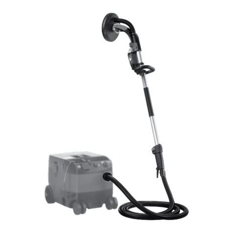
Virutex
Virutex LPC97S User manual
Virutex
Virutex LB31E User manual
Virutex
Virutex LR46L User manual
Virutex
Virutex RTE84H User manual
Virutex
Virutex LR84H User manual
Virutex
Virutex RTE46L User manual
Virutex
Virutex LR46L User manual
