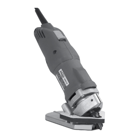
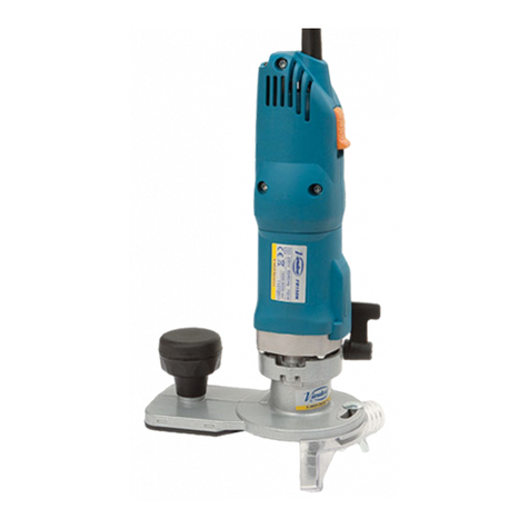
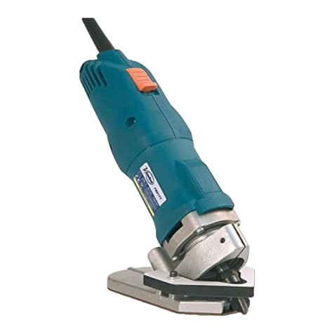
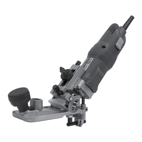
6
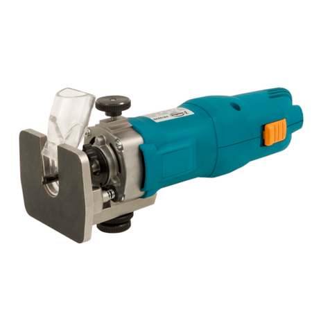
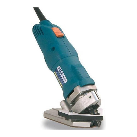
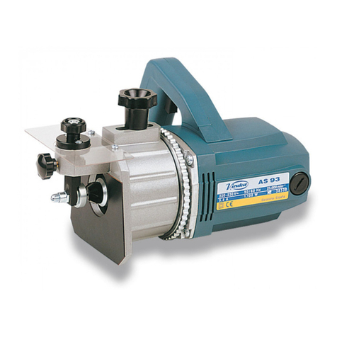
a front feeler that prevents the rim from becoming
damaged and allows for quick, easy trimming, giving
a perfect finish.
The machine is fitted with a dust collection connector,
to which one of ourdust collectorsAS182K,AS282K, or
any other industrial dust collector may be fitted, using
a standard dust collector attachment (ref. 6446073).
5. PREPARING THE MOULDING
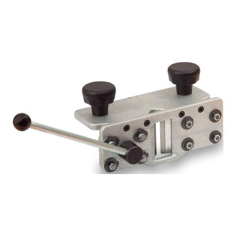
To trim concave radiuses, a plate must be fitted
between the base of the work top and the rim. The
size of the plate depends on the desired radius, as
shown in (Fig. 3).
The maximum trimmer radius that can be fitted on the
machine is 10 mm and the minimum is 5 mm.
6. STARTING AND STOPPING THE MACHINE
To start the machine, press button A forward (Fig. 1)
to the "on" position. To stop the machine, simply press
the back of the switch and it will return to the "off"
position. The electronic control enables you to work
at the ideal speed for each type of job and cutter bit.
To do this, use button B (Fig. 1 and 2).
7. ADJUSTING THE BIT HEIGHT
WARNING! Disconnect the machine from the mains
before making any adjustments to the machine.
Protector C does not need to be removed in order to
adjust the bit height (Fig. 4).
Loosen screw D (Fig. 4) using key E (Fig. 4) until
the motor body F can move. Turn the eccentric G
(Fig. 4) using the same key E (Fig. 4) until the edge
of the cutter bit with radius H (Fig. 5) is level with the
base I (Fig. 5) and firmly tighten screw D (Fig. 4) in
this position.
8. ADJUSTING THE FEELER
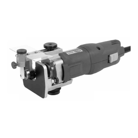
The machine has a feeler C (Fig. 5 and 6) which serves
as a guide and support while trimming.
To adjust the feeler, loosen the two screws J (Fig. 6)
with key E (Fig. 6) and move the sensor until edge H
(Fig. 6) of the bit is level with the sensor, taking into
consideration its 360° rotation (Fig. 6).
To ensure precise alignment, use the support ruler K
(Fig. 6). Once the correct position of the bit has been
established, tighten the two screws J again (Fig. 6).
Before carrying out the radius trim on the work top (Fig.
7), do a test trim to check that the height of the cutter
bit and the position of the feeler are set correctly.
9. CHANGING THE BIT
WARNING! Disconnect the machine from the mains
before performing this operation. To change the cutter
bit, first remove the feeler C (Fig. 6), removing the
screws J (Fig. 6). Block the motor shaft using key L,
unscrew the nut with the key M (Fig. 8), remove the
worn bit and insert a new one. Hold it in position by
tightening the nut with key M and let it slide until the
edge rests on the support surface.
Adjust the height of the bit, as explained in the cor-
responding section (Fig. 5).
10. MAINTENANCE. CARBON
BRUSHES AND COMMUTATOR
WARNING! Disconnect the machine from the power
supply before any maintenance operation.
Remove the screws N (Fig. 9) that hold the side covers
O (Fig. 9)and separate them.Remove the brush-holder
P (Fig. 10) with small screwdriver Q, using one of the
brush-holder side tabs to lever it out. Push back the
end of spring R. Keep it in this position to remove the
brush and replace it with a new genuine Virutex brush.
Reinsert the brush-holder, ensuring that it is firmly
positioned in the casing and that each of the brushes
exerts a small amount of pressure on the collector.
Re-attach the covers O withthe corresponding screws,
making sure that no wires get caught in the process.
It is advisable to leave the machine running for 15
minutes after the brushes have been changed.
If the collector burns or juts out, it should be serviced
by a VIRUTEX technical service. Always keep the
cable and plug in good service condition.
11. LUBRICATION AND CLEANING
The machine comes fully lubricated from the factory
and does not require special care during its working
life. It is important to always clean the machine care-
fully after use with a dry air blower.
Keep the power cable in perfect working condition.
12. NOISE LEVEL AND VIBRATIONS
These levels have been measured according to the
European Standard EN50144.
The noise level inthe workplace could goover 85dB(A).
In this case it is necessary for the user to wear noise
protection.
13. WARRANTY
All VIRUTEX power toolsare guaranteed for 12months
from the dateof purchase,excluding any damagewhich
is a result of incorrect use or of natural wear and tear
on the machine.All repairs should be carried out by the
official VIRUTEX technical assistance service.
VIRUTEX reserves the right to modify its products
without prior notice
FRAISEUSE D'ANGLE FR217S
IMPORTANT
ATTENTION! Avant d'utiliser la machine, lisez at-
tentivement ce MANUEL D'INSTRUCTIONS et la
BROCHURE D'INSTRUCTIONS GÉNÉRALES DE
SÉCURITÉ qui vous sont fournis avec cette machine.
Assurez-vous de bien avoir tout compris avant de
commencer à travailler sur la machine.
Gardez toujours ces deux manuels d'instructions à
Français


