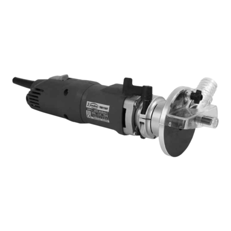
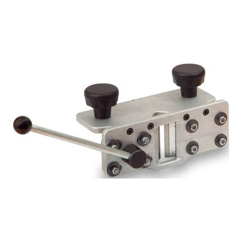
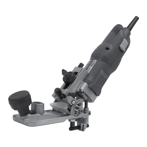
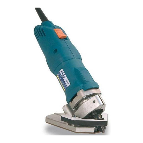
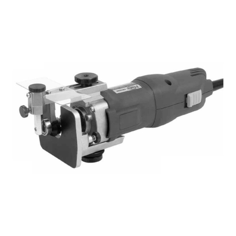
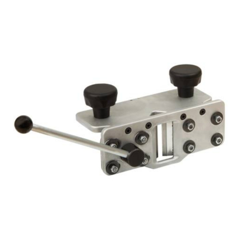
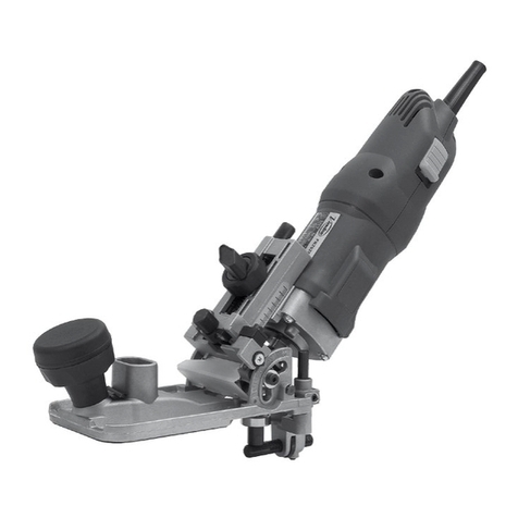
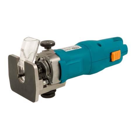
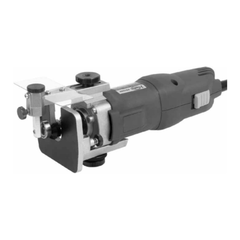
Virutex RC321S DOBLE User manual

Retestador de cantos DOBLE
DOUBLE edge trimmer
Coupe en bout DOUBLE
DOPPEL-Kantenkappgerät
Intestatore di bordi DOPPIO
Retestador de orlas DUPLO
DOUBLE торцевой подрезатель кромочного материала
Gilotyna do obrzeży "DOBLE"
RC321S DOBLE
MANUAL DE INSTRUCCIONES
OPERATING INSTRUCTIONS
MODE D’ EMPLOI
GEBRAUCHSANWEISUNG
MANUALE D’ISTRUZIONI
MANUAL DE INSTRUÇÕES
ИНСТРУКЦИЯ ПО ЭКСПЛУАТАЦИИ
INSTRUKCJA OBSŁUGI

2
Fig. 2
Fig. 3
MANUAL DE INSTRUCCIONES
OPERATING INSTRUCTIONS
MODE D'EMPLOI
GEBRAUCHSANWEISUNG
MANUALE D'ISTRUZIONI
MANUAL DE INSTRUÇÕES
ИНСТРУКЦИЯ
ПО
ЭКСПЛУАТАЦИИ
INSTRUKCJA OBSŁUGI
ИНСТРУКЦИЯ
ПО
ЭКСПЛУАТАЦИИ
página/page
Seite/pagina
страница/strona
ESPAÑOL Retestador de cantos RC321S doble
4
ENGLISH RC321S Double edge trimmer
4
FRANÇAIS Coupe en bout RC321S double
5
DEUTSCH DOPPEL-Kantenkappgerät RC321S
6
ITALIANO Intestatore di bordi RC321S doppio
7
PORTUGUÉS Retestador de orlas RC321S duplo
8
РУССКИЙ RC321S DOUBLE торцевой подрезатель кромочного материала
8
POLSKI RC321S Gilotyna do obrzeży "DOBLE"
10
B
A
Fig. 4
D
C
E
Fig. 1

3
Fig. 5 Fig. 6
Fig. 7
Fig. 9 Fig. 10
F
G
H
IJ
LM K
Fig. 8
NP
O
Q
R
Radio Curvatura tablero

4
ESPAÑOL
RETESTADOR DE CANTOS RC321S
DOBLE
1. DESCRIPCIÓN
El retestador de cantos RC321 DOBLE, permite el corte
enrasado del sobrante de cinta, delantero y trasero, en
el aplacado de cantos rectos (Fig. 1), así como la unión
solapadaenchapadodecantosdesiluetascurvas(Fig.2).
Capacidad de corte máxima con
canto de hasta 1 mm......................................55 mm
Capacidad de corte máxima con
canto de hasta 2 mm.......................................45 mm
Capacidad de corte máxima con
canto de hasta 3 mm.........................................25 mm
2. UTILIZACIÓN COMO RETESTADOR DE CAN-
TOS RECTOS
El brazo de regulación A, (Fig. 3) debe estar en su po-
sición de regulación mínima, según se representa en la
Fig. 3. El pomo B, (Fig. 3) debe estar apretado para fijar
dicha posición.
Coloque el retestador sobre el canto del tablero (Fig. 4),
de modo que la cinta sobrante pase entre las cuchillas y
el tope C, (Fig. 4) quede apoyado sobre el mismo canto.
Sujete el retestador, con una mano en el pomo D, (Fig.
4), contra la cara del panel y corte el sobrante de cinta
accionando la palanca E (Fig. 4), con la otra mano.
3. UTILIZACIÓN COMO RECORTADOR DE CAN-
TOS CURVOS
Al preparar el canto, el corte inicial F (Fig.5), debe ser lo
mas recto posible a fin de disponer de una buena refe-
rencia. Cortaremos el canto con un excente no inferior
a 20 mm (G, Fig. 5). Pegamos el canto dejando 50 mm
(H, Fig. 5), sin pegar para poder colocar el recortador.
El brazo de regulación I (Fig. 6) debe estar en su posi-
ción de regulación máxima, según se representa en la
Fig. 6. El pomo J (Fig. 6) debe estar apretado para fijar
dicha posición.
Colocar el retestador, apoyado sobre la superficie del
tablero, pasando el canto no pegado entre las cuchillas
(Fig. 7).
Desplazar el retestador hasta que contacte con el punto
de referencia K (Fig. 7) y el tope L (Fig. 7) contacte con
la superficie del canto.
Llegados a este punto podemos realizar un primer corte
de aproximación.
El ajuste del brazo regulación M (Fig. 7) varia en función
de la curvatura del tablero (Fig. 5), por lo que su ajuste
inicial se deberá realizar considerando que desplazando
hacia el signo “+” (N, Fig. 8) dejaremos mas excedente
en el corte y desplazando hacia el signo “-” (O, Fig. 8)
dejaremos menos.
La siguiente tabla indica, como orientación, los valores
del indice (P, Fig. 8) en función del radio de curvatura del
tablero (Fig 5). Cada usuario debe afinar estos valores
según su experiencia y forma de trabajar. Es reco-
mendable
unprimercortedeaproximaciónaunindicesuperiorpara
luego determinar el indice del corte definitivo y poder
repetir
cortes mientras no varíe la curvatura del tablero.
Radio Curvatura (mm) Indice
300 3,5
500 5
1000 5,5
2000 6
4. SUSTITUCIÓN DE LAS CUCHILLAS
Para sustituir las cuchillas, basta con extraer los tornillos
de sujeción (Q y R, Figs. 9 y 10).
5. GARANTÍA
Todos los productos VIRUTEX, tienen una garantía válida
de 12 meses a partir del día de suministro, quedando
excluidas todas las manipulaciones o daños ocasionados
por manejos inadecuados o por desgaste natural.
Para cualquier reparación dirigirse al servicio oficial de
asistencia técnica VIRUTEX.
VIRUTEX, S.A. se reserva el derecho de modificar sus
productos sin previo aviso.
ENGLISH
RC321S DOUBLE EDGE TRIMMER
1. DESCRIPTION
The RC321S DOUBLE edge trimmer permits the flush
trimming of surplus tape on the front and back when
banding straight edges (Fig. 1) and overlapping joints
on veneered edges in rounded corners (Fig. 2).
Maximum cutting capacity with
edge of up to 1 mm.....................................55 mm
Maximum cutting capacity with
edge of up to 2 mm.....................................45 mm
Maximum cutting capacity with
edge of up to 3 mm.....................................25 mm

5
2. USE IN TRIMMING STRAIGHT EDGES
Regulation arm A, (Fig. 3) should be in the minimum
regulation position, as shown in Fig. 3. Knob B, (Fig. 3)
should be tightened to secure that position.
Place the trimmer on the edge of the board (Fig. 4), so
that the surplus tape passes between the blades and
stop C (Fig. 4) is resting on the same edge.
With one hand on knob D, hold the trimmer (Fig. 4)
against the panel face and cut the surplus tape with
lever E (Fig. 4) using your other hand.
3. USE IN CUTTING ROUNDED CORNERS
When preparing the edge, the initial cut F (Fig. 5) should
beas straight as possible,to obtain a goodreference. Cut
the edge leaving an excess of no less than 20 mm (G, Fig.
5). Glue the edge, leaving a space of 50 mm (H, Fig. 5)
without gluing, so that the trimmer can be positioned.
Regulation arm I, (Fig. 6) should be in the maximum
regulation position, as shown in Fig. 6. Knob J, (Fig. 6)
should be tightened to secure that position.
Position the trimmer so that it is resting on the board sur-
faceandpass the unglued edgebetweentheblades(Fig.7).
Move the trimmer until it touches reference point K (Fig.
7) and stop L (Fig. 7) touches the surface of the edge.
At this point, make the first cut.
The adjustment of regulation arm M (Fig. 7) varies,
depending on the board curvature, so the initial ad-
justment should be made considering that if moving
towards the “+” sign (N, Fig. 8) there will be greater
excess in the cut and if moving towards the “-” sign (O,
Fig. 8) there will be less.
The following table indicates, as a guidance, the value
of the index P (Fig. 8) depending the radius of the
board (Fig. 5). Each user must adjust this value as per
his experience and way to work.
It is advisable to make a first cut to a superior value of
the index and later adjust it to the definitive value to
be able to make repetitive cuts on other boards with
the same radius.
Radius (mm) Index
300 3,5
500 5
1000 5,5
2000 6
4. REPLACING THE BLADES
Toreplacetheblade,simplyremove the fastening screws
(Q and R, Figs. 9 and 10).
5. GUARANTEE
All VIRUTEX products are guaranteed for 12 months as
of the date of supply. The guarantee does not include
unauthorised manipulation or damage caused by inco-
rrect use or natural wear.
For any repairs, contact the official VIRUTEX Technical
Assistance service.
VIRUTEX, S.A. reserves the right to modify its products
without prior notification.
FRANÇAIS
COUPE EN BOUT RC321S DOUBLE
1. DESCRIPTION
L'unité de coupe en bout RC321S DOUBLE permet de
couper à ras l'excédent de bande avant et arrière, lors
du placage de chants droits (Fig. 1), ainsi que la jonction
superposée, lors du placage de chants courbes (Fig. 2).
Capacité de coupe maximale avec chant
de jusqu’à 1 mm..................................................55 mm
Capacité de coupe maximale avec
chant de 2 mm...................................................45 mm
Capacité de coupe maximale avec
chant de 3 mm...................................................25 mm
2. UTILISATION COMME UNITÉ DE COUPE DE
CHANTS DROITS
Le bras de réglage A (Fig. 3) doit être en position de
réglage minimum, comme indiqué sur la Fig. 3. Il faut
serrerle bouton B(Fig.3)pourlefixer dans cetteposition.
Poser l'unité de coupe sur le chant du panneau (Fig.
4) de façon à ce que l'excédent de bande passe entre
les couteaux et que la butée C (Fig. 4) s'appuie sur le
chant lui-même.
Avec une main sur le bouton D, tenir l'unité de coupe
(Fig.4)contrelecôté du panneau et couper l'excédent de
bande,en actionnant le levier E (Fig. 4) avec l'autre main.
3. UTILISATION COMME UNITÉ DE COUPE DE
CHANTS COURBES
Lors de la préparation du chant, la première coupe F
(Fig. 5) doit être la plus droite possible, afin de disposer
d'une bonne référence. Couper le chant avec un excé-
dent non inférieur à 20 mm (G, Fig. 5). Coller le chant
en laissant 50 mm (H, Fig. 5) sans colle, pour pouvoir
poser l'unité de coupe.
Le bras de réglage I (Fig. 6) doit être en position de
réglage maximum, comme indiqué sur la Fig. 6. Il faut
serrerleboutonJ(Fig. 6) pour le fixer dans cette position.
Placer l'unité de coupe en l'appuyant sur la surface du
panneau et faire passer le chant non collé entre les
couteaux (Fig. 7).

6
Déplacer l'unité de coupe jusqu'à ce qu'elle entre en
contact avec le point de référence K (Fig. 7) et que la
butée L (Fig.7) touche la surface du chant.
À ce stade, il est possible de réaliser une première coupe
d'approche.
Le réglage du bras M (Fig. 7) varie en fonction de la
courbure du panneau; le réglage initial doit donc être
réalisé sachant que si on le déplace vers le signe «+» (N,
Fig. 8), on laissera plus d'excédent lors de la coupe et
que si on le déplace vers le signe «-» (O, Fig. 8), on en
laissera moins.
Le tableau en bas indique, comme orientation, la valeur
de l'index p (Fig. 8) en fonction du rayon de courbure
du panneau (Fig. 5). Chaque utilisateur doit ajuster ces
valeurs d'après son expérience et forme de travailler. Il
est recommandable de faire une première coupe à un
index supérieur pour après fixer l'index de coupe défi-
nitive et pouvoir répéter les coupes sur des panneaus
du même rayon.
Rayon (mm) Index
300 3,5
500 5
1000 5,5
2000 6
4. REMPLACEMENT DES COUTEAUX
Pour remplacer les couteaux, il suffit de retirer les vis
de fixation (Q et R, Fig. 9 et 10).
5. GARANTIE
Tous les produits VIRUTEX ont une garantie valable 12
mois à partir de la date de livraison, tous les dommages
ou réparations causés par un maniement incorrect ou
par une usure naturelle en étant exclus.
Pour toute réparation, s'adresser au service officiel
d'assistance technique VIRUTEX.
VIRUTEX, S.A. se réserve le droit de modifier ses produits
sans préavis.
DEUTSCH
DOPPEL-KANTENKAPPGERÄT RC321S
1. BESCHREIBUNG
Das DOPPEL-Kantenkappgerät RC321 ermöglicht
das bündige Abschneiden der hinteren und vorderen
Überstände von angeleimten geraden Kanten (Abb. 1)
sowie die überlappende Verbindung von gebogenen
Kantenfurnieren (Abb. 2).
Maximale Schnittlänge bei
bis zu 1 mm dicken Kanten...........................55 mm
Maximale Schnittlänge bei
bis zu 2 mm dicken Kanten..........................45 mm
Maximale Schnittlänge bei
bis zu 3 mm dicken Kanten...........................25 mm
2. VERWENDUNG DES KANTENKAPPGERÄTS
FÜR GERADE KANTEN
Der Einstellarm A (Abb. 3) muss sich wie in Abb. 3 gezeigt
in der Stellung für die minimale Einstellung befinden.
Der Griff B (Abb. 3) muss fest angezogen sein, um den
Arm in seiner Stellung zu fixieren.
Setzen Sie das Kantenkappgerät an der Kante der Platte
an (Abb. 4), sodass der Überstand zwischen den Messern
durchläuft und der Anschlag C (Abb. 4) sich an der
Kante aufstützt.
DrückenSiedasKantenkappgerätmiteinerHandamGriff
D (Abb. 4) gegen die Oberseite der Platte und betätigen
Sie den Hebel E (Abb. 4) mit der anderen Hand, um den
Überstand abzuschneiden.
3. VERWENDUNG DES KANTENKAPPGERÄTS
FÜR GEBOGENE KANTEN
Bei der Vorbereitung der Kante muss der erste Kantens-
chnitt F (Abb. 5) möglichst gerade ausgeführt werden,
um eine gute Bezugslinie zu erhalten. Schneiden Sie
die Kante mit einem Überschuss von mind. 20 mm (G,
Abb. 5). Kleben Sie die Kante und lassen Sie dabei ein
nicht festgeklebtes Stück von 50 mm (H, Abb. 5) zum
Ansetzen des Kantenschneiders übrig.
Der Einstellarm I (Abb. 6) muss sich wie in Abb. 6 gezeigt
in der Stellung für die maximale Einstellung befinden.
Der Griff J (Abb. 6) muss fest angezogen sein, um den
Arm in seiner Stellung zu fixieren.
Setzen Sie das Kantenkappgerät auf der Platte an,
sodass die nicht verklebte Kante zwischen den Messern
durchläuft (Abb. 7).
SchiebenSie das Kantenkappgerät bis zum Bezugspunkt
K (Abb. 7), sodass der Anschlag L (Abb. 7) die Oberfläche
der Kante berührt.
An dieser Stelle kann ein erster Vorschnitt erfolgen.
Die Einstellung des Einstellarms M (Abb. 7) erfolgt je
nach Rundung der Platte. Bei der Grundeinstellung ist
zu berücksichtigen, dass beim Verschieben in Richtung
des Symbols "+“ (N, Abb. 8) mehr Überschuss beim
Schnitt erzielt wird und beim Verschieben in Richtung
des Symbols "-“ (O, Abb. 8) weniger Überschuss.
Die folgende Tabelle zeigt den Richtwert vom Index
P (Abb. 8) in Abhängigkeit vom Radius der Holzplatte
(Bild5).JederAnwendermussdiesenWertentsprechend
seiner Erfahrung und Arbeitsweise anpassen.
Eswirdempfohlen, einen ersten Schnitt auf einemhöhe-
renWertdesIndexeszumachenundihnanschließendauf
den endgültigen Wert einzustellen, um wiederkehrende

7
Schnitte auf anderen Holzplatte mit dem selben Radius
durchführen zu können.
Radius (mm) Index
300 3,5
500 5
1000 5,5
2000 6
4. AUSTAUSCHEN DER MESSER
Zum Austauschen der Messer sind lediglich die Befes-
tigungsschrauben (Q und R, Abb. 9 und 10) heraus-
zudrehen.
5. GARANTIE
Für alle VIRUTEX-Maschinen wird eine 12-monatige
Gewährleistungab Lieferdatum gewährt.Eingriffedurch
unbefugtes Personal bzw. Schäden, die auf unsachge-
mäße Handhabung oder auf natürlichen Verschleiß
zurückzuführensind,werdendurchdieseGewährleistung
nicht abgedeckt.
Zur Durchführung von Reparaturen wenden Sie sich
bitte an den VIRUTEX-Kundendienst.
VIRUTEX, S.A. behält sich das Recht vor, technische
Änderungen an seinen Produkten ohne vorherige
Ankündigung vorzunehmen.
ITALIANO
INTESTATORE DI BORDI RC321S DOPPIO
1. DESCRIZIONE
L’intestatoredibordiRC321SDOPPIOconsenteditagliare
a raso l’eccedenza di nastro anteriore e posteriore nella
bordatura di elementi dritti (Fig. 1), così come l’unione
sovrappostainlaminatodibordidisagomecurve(Fig.2).
Massima capacità di taglio con
bordo fino a 1 mm.....................................55 mm
Massima capacità di taglio con
bordo di 2 mm...........................................45 mm
Massima capacità di taglio con
bordo di 3 mm..........................................25 mm
2. USO COME INTESTATORE DI BORDI DRITTI
Il braccio di regolazione A (Fig. 3) deve stare nella
posizione di regolazione minima, come rappresentato
in Fig. 3. La manopola B (Fig. 3) deve essere ben serrata
per fissarne la posizione.
Posizionare l’intestatore sul bordo del pannello (Fig. 4)
di modo che il nastro eccedente passi tra le lame e il
fermo C (Fig. 4) rimanga appoggiato sul bordo stesso.
Con una mano sulla manopola D (Fig. 4), tenere fermo
l'intestatore contro la superficie del pannello e tagliare
l'eccedenza di nastro azionando la leva E (Fig. 4) con
l'altra mano.
3. USO COME RIFILATORE DI BORDI CURVI
Quando si prepara il bordo, il taglio iniziale F (Fig.
5) deve essere il più dritto possibile in modo tale da
disporre di un buon elemento di riferimento. Tagliare il
bordo con un’eccedenza non inferiore a 20 mm (G, Fig.
5). Incollare il bordo tralasciando 50 mm (H, Fig. 5) per
poter posizionare il rifilatore.
Il braccio di regolazione I (Fig. 6) deve stare nella po-
sizione di regolazione massima, come rappresentato in
Fig. 6. La manopola J (Fig. 6) deve essere ben serrata per
fissarne la posizione.
Posizionare l’intestatore appoggiandolo sulla superficie
del pannello e far passare il bordo non incollato tra le
lame (Fig. 7).
Spostare l’intestatore fino a toccare il punto di riferi-
mento K (Fig. 7) e fino a che il fermo L (Fig. 7) entri in
contatto con la superficie del bordo.
Arrivati a questo punto, possiamo eseguire un primo
taglio preliminare.
La messa a punto del braccio di regolazione M (Fig. 7)
varia in funzione della curvatura del pannello, per cui
la regolazione iniziale dovrà effettuarsi tenendo conto
che se lo si sposta verso il segno "+" (N, Fig. 8) lasceremo
più eccedenza nel taglio, mentre se lo si sposta verso il
segno "-" (O, Fig. 8) ne lasceremo meno.
La seguente tavola indica, orientativamente, I valori
dell’indice (P.Fig.8) in funzione dl raggio di curvatura
del pannello (Fig.5)
Ognioperatore deve ottimizzarequestivaloriinfunzione
della sua personale esperienza e modo di lavoro.
E’ consigliabile effettuare un primo taglio con approssi-
mazione all’indice superiore per poi determinare l’indice
di taglio definitivo e poter quindi ripetere le intestature
se la curvatura del pannello non varia.
Raggio di curvatura (mm)
Indice
300 3,5
500 5
1000 5,5
2000 6
4. SOSTITUZIONE DELLE LAME
Per sostituire le lame, basta estrarre le viti di fissaggio
(Q e R, Fig. 9 e 10).

8
5. GARANZIA
Tutti prodotti VIRUTEX hanno una garanzia di 12 mesi
a partire dalla data di consegna, eccezion fatta per le
eventuali manomissioni o i danni causati da un uso
improprio o dalla normale usura.
Per qualsiasi riparazione, rivolgersi al Servizio di Assis-
tenza Tecnica VIRUTEX.
VIRUTEX, S.A. si riserva il diritto di modificare i propri
prodotti senza preavviso.
PORTUGUÉS
RETESTADOR DE ORLAS RC321S DUPLO
1. DESCRIÇÃO
O retestador de orlas RC321S DUPLO permite o corte
nivelado do excedente da fita dianteira e traseira na
aplicação de orlas retas (Fig. 1), bem como a ligação
sobreposta quando se chapeiam orlas de perfis curvos
(Fig. 2).
Capacidade de corte máxima com
orla de até 1 mm..............................................55 mm
Capacidade de corte máxima com
orla de até 2 mm...............................................45 mm
Capacidade de corte máxima com
orla de até 3 mm.................................................25 mm
2. UTILIZAÇÃO COMO RETESTADOR DE ORLAS
RETAS
O braço de regulação A. (Fig. 3) deverá estar na posição
de regulação mínima, conforme o que é apresentado na
Fig. 3. A manete B (Fig. 3) deverá estar apertada para
fixar a referida posição.
Coloque o retestador sobre a orla do tabuleiro (Fig. 4),
de forma que a fita excedente passe entre as lâminas e o
fim de curso C (Fig. 4) fique apoiado sobre a própria orla.
Segure o retestador com uma mão na manete D (Fig. 4)
contraoladodopainel,ecorteafitaexcedenteacionando
a alavanca E (Fig. 4) com a outra mão.
3. UTILIZAÇÃO COMO RECORTADOR DE ORLAS
CURVAS
Ao preparar a orla, o corte inicial F (Fig. 5) deverá ser o
mais reto possível para se dispor de uma boa referência.
Cortaremos a orla com um excedente não inferior a 20
mm (G, Fig. 5). Colamos a orla deixando 50 mm (H, Fig.
5) sem colar para poder colocar o recortador.
O braço de regulação I (Fig. 6) deverá estar na posição
de regulação mínima, conforme o que é apresentado na
Fig. 6. A manete J (Fig. 6) deverá estar apertada para
fixar a referida posição.
Colocar o retestador, apoiado na superfície do tabuleiro,
passando a orla não colada entre as lâminas (Fig. 7).
Deslocar o retestador até entrar em contacto com o
ponto de referência K (Fig. 7) e o fim de curso L (Fig. 7)
até entrar em contacto com a superfície da orla.
Chegados a este ponto, podemos fazer um primeiro
corte de aproximação.
O ajustamento do braço de regulação M (Fig. 7) varia
em função da curvatura do tabuleiro e, portanto, o seu
ajustamento inicial deverá realizar-se considerando
que se deslocarmos na direção do sinal “+” (N, Fig. 8),
deixaremos mais excedente no corte, e se deslocarmos
na direção do sinal “-” (O, Fig. 8), deixaremos menos.
A seguinte tabela indica, como orientação, os valores
do indice (P, Fig. 8) em função do raio de curvatura do
painel (Fig. 5). Cada utilizador deve afinar estes valores
de acordo com a sua experiência e forma de trabalho. É
recomendável um primeiro corte de aproximação num
valor superior para de seguida determinar o indice de
corte definitivo e poder repetir cortes desde que não
altere a curvatura do painel
Raio Curvatura (mm)
Indice
300 3,5
500 5
1000 5,5
2000 6
4. SUBSTITUIÇÃO DAS LÂMINAS
Para substituir as lâminas, basta extrair os parafusos de
fixação (Q e R, Fig. 9 e 10).
5. GARANTIA
Todos os produtos VIRUTEX gozam de uma garantia
válida pelo prazo de 12 meses a partir da data do seu
fornecimento, excluindo-se desta garantia todos os
manuseamentos ou danos causados por utilizações
indevidas ou por desgaste natural.
Para qualquer reparação, dirija-se ao serviço oficial de
assistência técnica VIRUTEX.
A VIRUTEX, S.A. reserva-se o direito de modificar os seus
produtos sem aviso prévio.
РУССКИЙ
RC321S DOUBLE ТОРЦЕВОЙ
ПОДРЕЗАТЕЛЬ КРОМОЧНОГО МАТЕРИАЛА
1. ОБЩЕЕ ОПИСАНИЕ
Торцевой подрезатель RC321S DOUBLE

9
позволяет удалять передний и задний торцевые
свесы кромочного материала при облицовке
прямолинейных деталей (Fig. 1) и удаления
излишка для стыковки кромочного материала
при обработке выгнутых криволинейных
деталей (Fig. 2).
Максимальная ширина кромочного материала
при толщине до 1 мм.........55 мм
Максимальная ширина кромочного материала
при толщине до 2 мм.........45 мм
Максимальная ширина кромочного материала
при толщине до 3 мм........25 мм
2. ИСПОЛЬЗОВАНИЕ ПРИ УДАЛЕНИИ
СВЕСОВ НА ПРЯМОЛИНЕЙНЫХ ДЕТАЛЯХ
Установите упор A (Fig. 3) в крайнее нижнее
положение, как указано на рисунке Fig. 3 и
зафиксируйте его в этом положении при помощи
фиксатора B, (Fig. 3).
Установите подрезатель на обрабатываемой
детали (Fig. 4) таким образом, чтобы излишек
кромочного материала проходил между ножами,
а основание упора C (Fig. 4) базировалось на
торцевой поверхности детали.
Удерживая подрезатель при помощи рукоятки
D (Fig. 4) одной рукой, удалите излишек
кромочного материала, нажав на рычаг E (Fig.
4) другой рукой.
3. ИСПОЛЬЗОВАНИЕ ПРИ ОБРАБОТКЕ
КРИВОЛИНЕЙНЫХ ДЕТАЛЕЙ
Для получения надлежащего результата
при стыковке кромочного материала на
криволинейном участке начальный срез F (Fig.
5) кромочного материала должен быть выполнен
на столько прямым, на сколько это возможно.
Удаляемый излишек кромочного материала при
стыковке должен быть не менее 20 мм (G, Fig.
5). Для возможности установки порезателя, при
приклейке кромочного материала, оставте не
приклеенным участок 50 мм (H, Fig. 5).
Установите упор I, (Fig. 6) в крайнее верхнее
положение, как указано на рисунке Fig. 6.
Зафиксируйте упор в выбранном положении
при помощи фиксатора J, (Fig. 6).
Установите подрезатель на обрабатываемую
деталь, пропустив неприклеенный участок
кромочного материала между ножами (Fig. 7).
Подвиньте подрезатель до его упора в
начальный срез кромочного материала K (Fig.
7) при этом основание упора L (Fig. 7) должно
касаться поверхности приклеенного кромочного
материала.
В данном положении сделайте первый срез.
Настройка положения штанги упора M (Fig.
7) осуществляется в зависимости от радиуса
кривизны детали в точке стыка, таким образом
настройка должна выполняться с учетом
того, что при смещении штанги упора по
направлению, отмеченному знаком “+” (N, Fig.
8) остаточная длина кромочного материала
после удаления излишка будет больше и,
соответственно, при смещении в сторону знака
“-” (O, Fig. 8) будет меньше.
После выполнения настройки, по достижении
требуемого результата стыковки, на шкале P (Fig.
8) будет отражено положение упора. Следующая
таблица приводит примерные рекомендации по
установке индекса P (Fig. 8) в зависимости от
радиуса кривизны обрабатываемой детали (Fig.
5). Каждый пользователь должен производить
дополнительные настройки на основе своего
опыта и способа использования инструмента.
Рекомендуется выполнить предварительный
рез с увеличенным значением индекса, а
затем, подстроить до указанного значения.
Настоятельно рекомендуется выполнить
пробный рез на тестовой детали с аналогичным
радиусом.
Радиус (мм) Индекс
300 3,5
500 5
1000 5,5
2000 6
4. ЗАМЕНА НОЖЕЙ
Для замены ножей просто отверните
фиксирующие их винты (Q и R, Figs. 9 и 10).
5. ГАРАНТИЙНЫЕ ОБЯЗАТЕЛЬСТВА
Все электроинструменты фирмы Virutex
имеют гарантию 12 месяцев со дня покупки.
Гарантия не распространяется на те случаи,
когда повреждение явилось результатом
неправильной эксплуатации или естественного
износа. При необходимости ремонта
обращайтесь в пункты техобслуживания или
уполномоченным представителям фирмы
Virutex.
Компания VIRUTEX оставляет за собой
право вносить изменения в конструкцию
или стандартный комплект поставки без
предварительного уведомления.

10
Р O L S K I
RC321S GILOTYNA DO OBRZEŻY "DOBLE"
1. OPIS
Gilotyna do obrzeży RC321S "DOBLE" umożliwia
cięcie nadmiaru obrzeża na równo z krawędzią
płyty, na początku i na końcu oklejonej, prostej
krawędzi (Rys. 1). Pozwala również na dokładne
docięcie obrzeża w punkcie styku przy oklejaniu
płyt okrągłych lub owalnych.
Maksymalna szerokość cięcia przy obrzeżu o
grubości do 1 mm.......55 mm
Maksymalna szerokość cięcia przy obrzeżu o
grubości do 2 mm.....45 mm
Maksymalna szerokość cięcia przy obrzeżu o
grubości do 3 mm...........25 mm
2. USTAWIENIE GILOTYNKI DO OBCINANIA
NADMIARU OBRZEŻA NA KOŃCU PŁYT
Najpierw należy docisnąć uchwyt B (Rys. 3) i
następnie ustawić ramię regulujące (A, Rys. 3)
poziomo w pozycji minimalnej, jak jest pokazane
na Rys. 3.
Umieść gilotynkę na krawędzi płyty w taki spo-
sób (Rys. 4), aby nadmiar obrzeża znalazł się
pomiędzy ostrzami, a stoper (C, Rys. 4) opierał się
o krawędź płyty. Przytrzymaj gilotynę dociskając
ją do powierzchni płyty jedną ręką, za pomocą
uchwytu (D, Rys. 4), natomiast drugą ręką utnij
nadmiar obrzeża, pociągając dźwignię (E, Rys.
4) w kierunku drugiego uchwytu.
3. USTAWIENIE GILOTYNKI DO DOCINANIA
OBRZEŻA PRZY PŁYTACH OKRĄGŁYCH
Na początku należy zwrócić uwagę, aby przygo-
towane obrzeże było ucięte prosto (F, Rys. 5),
tak aby punkt odniesienia był właściwy. Obrzeże
powinno mieć przynajmniej 20 mm nadwyżki (G,
Rys. 5). Oklejamy panel, zostawiając 50 mm (H,
Rys. 5) bez oklejenia, tak aby było miejsce na
założenie gilotyny.
Ramię regulujące I (Rys. 6) należy podnieść do
góry do pozycji maksymalnej ( Rys. 6), dociskając
uprzednio uchwyt J (Rys. 6). Umieść gilotynkę
na krawędzi płyty w taki sposób, aby nieoklejony
nadmiar obrzeża znalazł się między ostrzami (Rys.
7). Następnie przesuń gilotynkę tak, aby dotknęła
punktu odniesienia K (Rys. 7) i stoper L (Rys. 7)
dotykał obrzeża i wykonaj cięcie próbne.
Dokładne ustawienie ramienia regulującego M
(Rys. 7) zależy od kształtu panelu. Przesunięcie
ramienia w stronę znaku "+" (N, Rys. 8) zostawi
większą nadwyżkę obrzeża, a przesunięcie w
stronę znaku "-" (O, Rys. 8) zmniejszy ta nadwyżkę.
Poniższa tabelka obrazuje, jako wstępna wska-
zówka, zależność wskaźnika P (Rys. 8) od pro-
mienia formatki (Rys. 5). Każdy użytkownik musi
jednak dopasować dokładną pozycję według jego
doświadczenia i w praktyce.
Wskazane jest, aby wykonać pierwsze cięcie z
zapasem (wyższa wartość wskaźnika) i później
dopasować ostateczną pozycję, aby móc dokonać
powtarzalnych cięć innych formatek o tym samym
promieniu.
Promień (mm) Wskaźnik
300 3,5
500 5
1000 5,5
2000 6
4. WYMIANA OSTRZY
Wymień ostrza zdejmując jedynie śrubki (Q i R,
Rys. 9 i 10).
5. GWARANCJA
Wszystkie produkty VIRUTEX posiadają 12
miesięczną gwarancję od daty zakupu. Wszel-
kie uszkodzenia wynikające z nieprawidłowego
użytkowania lub naturalnego zużycia nie
podlegają gwarancji. W przypadku jakichkolwiek
napraw należy skontaktować się z ocjalnym
posprzedażowym serwisem VIRUTEX.
VIRUTEX zastrzega sobie prawo do modykowania
swoich urządzeń bez wcześniejszego uprzedzenia.


Virutex, S.A.
Antoni Capmany, 1
08028 Barcelona (Spain)
www.virutex.es
5296613 122016
http://www.virutex.es/registre
Acceda a toda la información técnica.
Access to all technical information.
Accès à toute l’information technique.
Zugang zu allen technischen Daten.
Accedere a tutte le informazioni tecniche.
Aceso a todas as informações técnicas.
Dostęp do wszystkich informacji technicznych.
Доступ ко всей технической информации.
Other manuals for RC321S DOBLE
1
Table of contents
Other Virutex Trimmer manuals

Virutex
Virutex FR1217T User manual

Virutex
Virutex FR56E User manual

Virutex
Virutex FR217S User manual

Virutex
Virutex Wegoma KG30 User manual

Virutex
Virutex FR292R User manual

Virutex
Virutex WEGOMA KFR130N User manual

Virutex
Virutex FR256N User manual

Virutex
Virutex FR192N User manual

Virutex
Virutex FR217S User manual

Virutex
Virutex FR156N User manual

Virutex
Virutex AS93 User manual

Virutex
Virutex FR1156T User manual

Virutex
Virutex FR1817T User manual

Virutex
Virutex FR1192T User manual

Virutex
Virutex RC421 User manual

Virutex
Virutex FR156N User manual

Virutex
Virutex RC52P User manual

Virutex
Virutex PL11 User manual

Virutex
Virutex FR1292T User manual

Virutex
Virutex FR192VG User manual