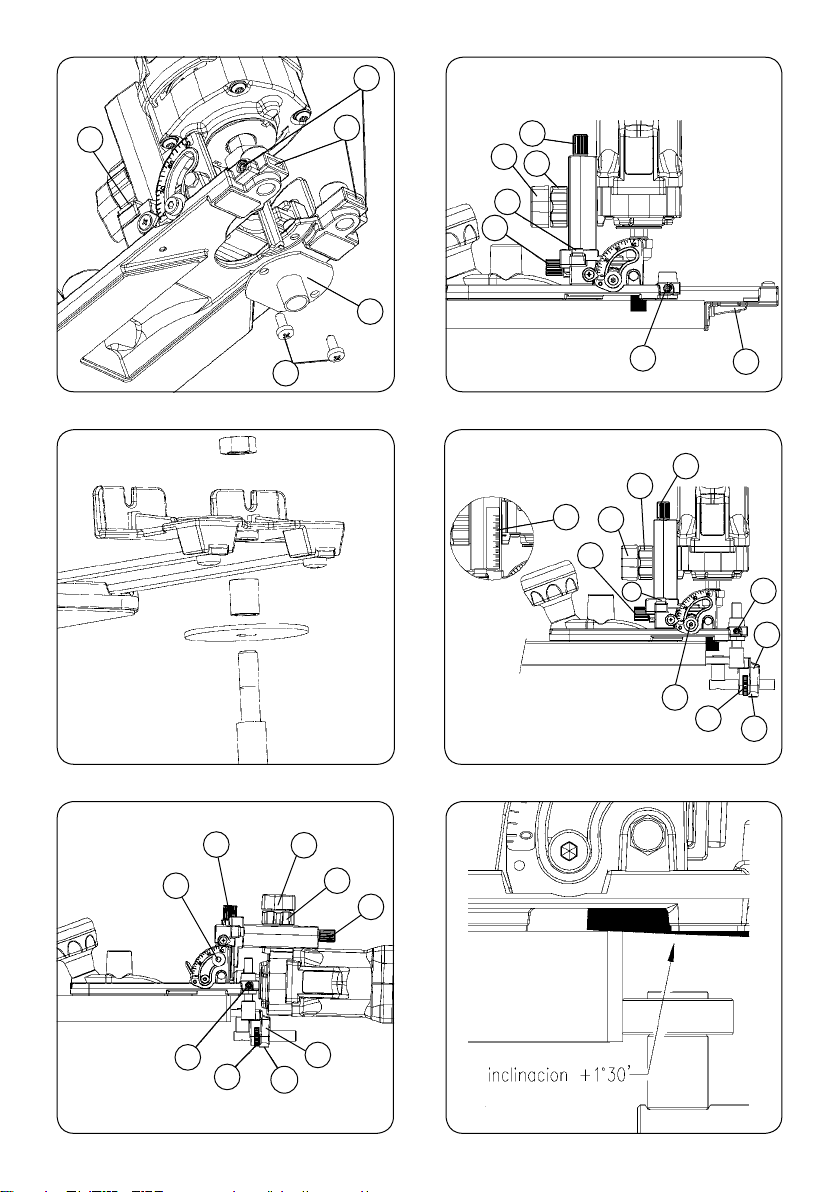
Virutex WEGOMA KFS135 User manual

MANUAL DE INSTRUCCIONES
OPERATING INSTRUCTIONS
MODE D’ EMPLOI
GEBRAUCHSANWEISUNG
MANUALE D’ISTRUZIONI
MANUAL DE INSTRUÇÕES
ИНСТРУКЦИЯ ПО ЭКСПЛУАТАЦИИ
INSTRUKCJA OBSŁUGI
Schwenkbare Kantenfräse
Fresadora de cantos inclinable
Tiltable trimmer
Affleureuse inclinable
Fresatrice inclinabile
Fresadora inclinável
Фрезер кромочный
Frezarka uchylna
KFS135

2
Abb. 2
Abb. 1
Abb. 3
DEUTSCH Schwenkbare Kantenfräse KFS135
6
ESPAÑOL Fresadora de cantos inclinable KFS135
11
ENGLISH KFS135 Tiltable trimmer
16
FRANÇAIS Affleureuse inclinable KFS135
20
ITALIANO Fresatrice inclinabile KFS135
24
PORTUGUÉS Fresadora inclinável KFS135
29
РУССКИЙ KFS135 Фрезер кромочный
33
POLSKI Frezarka uchylna KFS135
38
MANUAL DE INSTRUCCIONES
OPERATING INSTRUCTIONS
MODE D'EMPLOI
GEBRAUCHSANWEISUNG
MANUALE D'ISTRUZIONI
MANUAL DE INSTRUÇÕES
ИНСТРУКЦИЯ
ПО
ЭКСПЛУАТАЦИИ
INSTRUKCJA OBSŁUGI página/page
seite/pagina
страница/strona
H
A
D
X
B
H
O
A1
H
M1
M

3
Abb. 5
Abb. 4
Abb. 6
Abb. 8
Abb. 9
W
Abb. 7
H
C
L
K
E
H
B
E
DY
A
G1
N
F
M1
H
E
B
D
Y
A
H
FM1
M
N
BD
Y
A
M

4
Abb. 10
Abb. 11
Abb. 13
R
N
Abb. 12
a1 b1 a2 b2 c
d e ff1 g1
g2 hijk

5
Abb. 14 Abb. 15
Abb. 16
Abb. 17
Abb. 18
H
B3
R
TV
S
Q
Abb. 19

6
DEUTSCH
SCHWENKBAREFRÄSMASCHINEKFS135
Achtung!
Wichtiger Hinweis: Lesen Sie bitte vor
Benutzung der Maschine die beiliegen-
de GEBRAUCHSANWEISUNG und die
ALLGEMEINEN SICHERHEITSHINWEISE
sorgfältig durch.
Stellen Sie sicher, dass Sie sowohl die
Gebrauchsanweisung als auch die alle-
gemeinenSicherheitshinweiseverstanden
haben, bevor Sie die Maschine bedienen.
Bewahren Sie beide Gebrauchsanwei-
sungen zum späteren Nachschlagen auf.
1. SICHERHEITSHINWEISE
FÜR DEN BETRIEB DER FRÄSMASCHINE
Lesen Sie vor der Benutzung des Gerätes
die beigelegte Broschüre ALLGEMEINE
SICHERHEITSVORSCHRIFTEN sorgfältig
durch.
2. Prüfen Sie vor dem Anschließen der Maschine, ob die
Netzspannung mit den Angaben auf dem Typenschild
übereinstimmt.
3. Bringen Sie Ihre Hände nie innerhalb des Schleifbe-
reichs, und halten Sie die Maschine immer am dafür
vorgesehenen Griff.
4. Tragen Sie immer eine Schutzbrille.
5. Verwenden Sie immer Original-Werkzeuge von We-
goma by Virutex. Verwenden Sie niemals beschädigte
Abb. 23
Abb. 21
Abb. 20
Abb. 22
M1 M1
R1
R2

7
oder abgenutzte Werkzeuge.
6.Verwenden Sie ausschließlichFräser,derenSchaftdur-
chmesser den zu verwendenden Spannzangen und der
Geschwindigkeit der Fräsmaschine entspricht.
Ziehen Sie immer den Netzstecker, bevor
Sie Wartungsarbeiten an der Maschine
durchführen.
2. TECHNISCHE DATEN
Leistungsaufnahme..........................................................750W
Universalmotor.............................................................50/60Hz
Drehzahl..................................................14.000– 30.000U/min
ØFräsermax.........................................................................25mm
ØStandardspannzangen...............................................6-8 mm
Gewicht.................................................................................2,2kg
GewichteterakustischerDauerdruckpegelA..............83dBA
AkustischerDruckpegel A...............................................94dBA
Unsicherheit....................................................................K= 3dBA
Gehörschutz tragen!
Schwingungsgesamtwerte....................................ah:3,1m/s2
Unsicherheit...............................................................K= 1,5m/s2
3. STANDARDAUSSTATTUNG
Der Transportkoffer enthält folgende Elemente:
• Fräsmaschine KFS135 mit Spannzangen zu 8 mm.
• Gerader Fräser zum Profilieren und Kehlen D.18 LC. 20
• Schraubenschlüssel SW 11 mm für die Antriebswelle
Schraubenschlüssel SW 19 mm für Spannzangen-
Befestigungsmutter.
• Fühler
• Bremse Fräse mit Rollen
• Seitenwinkel mit Achse für Radiusfräsen
• Inbusschlüssel, SW 3 mm
• Gebrauchsanweisung und diverse Dokumente
4. BESCHREIBUNG DER FRÄSMASCHINE
Die Fräsmaschine KFS135 dient zum Profilieren von
Pressholz,zum Fräsen vonKehlungen,Absätzen, geraden
Rillen, Abschrägungen usw. Das Kopfstück ist von 0 bis
91,5° kippbar und erlaubt auch Rillen in Schrägkanten
sowie Abschrägungen mit zylindrischen Fräsern und
viele zusätzliche Anwendungen.
Der Rollenfühler mit Mikrometereinstellung ermöglicht
auch das Profilfräsen von Innenkurven mit einem Radius
von mehr als 52 mm.
Ebenso können Sie mit den in Abschnitt 11 genannten
Kopierschablonen oder Führungsschablonen Kopien
fräsen und mit Hilfe des Seitenwinkels und der Radiu-
sachse Kreise schneiden oder profilieren.
5. MONTAGE DES FRÄSERS UND DES ZUBEHÖRS
5.1MONTAGEUND AUSTAUSCHENDESFRÄSERS
Stellen Sie zur Vermeidung von
Vibrationen und der Lösung des
Spannfutters aus seiner Befestigung
sicher, dass das Spannfutter der Fräse
gut sitzt und in der richtigen Position
eingebaut ist (Abb. 23).
ZiehenSieden Netzstecker, bevor Sie die-
senEingriffanderMaschinedurchführen.
Zum Austauschen oder Montieren eines Fräsers der
Maschine (Abb. 1) blockieren Sie die Antriebswelle mit
dem Schlüssel U, lösen Sie die Mutter mit Hilfe des
Wartungsschlüssels Z, entfernen Sie den gebrauchten
Fräser und setzen Sie den neuen Fräser ein, indem Sie
ihn bis zum Anschlag in die Aufnahme stecken und diese
wieder mit Hilfe der Schlüssel festziehen.
Überprüfen Sie, ob der Durchmesser der
Spannzangen dem Schaftdruchmesser
des zu verwendenden Fräsers entspricht.
5.2 MONTAGE DES FÜHLERS UND DER BREMSE
ZiehenSieden Netzstecker, bevor Sie die-
senEingriffanderMaschinedurchführen.
Führen Sie die Fühlereinheit M (Abb. 2) durch die
Öffnungen O (Abb. 3) des Kopfstücks, und befestigen
Sie sie mit Hilfe der Schrauben H auf der gewünschten
Höhe (Abb. 2).
5.3 MONTAGE DES SEITENWINKELS
ZiehenSieden Netzstecker, bevor Sie die-
senEingriffanderMaschinedurchführen.
Führen Sie den Seitenwinkel W (Abb. 5) durch die Öff-
nungen C (Abb. 4) des Kopfstücks, und befestigen Sie ihn
mitHilfederSchrauben H in dem gewünschten Abstand.
5.4 MONTAGE DER RADIUSACHSE
Montieren Sie die Mittenachse zusammen mit dem
Abstandshalter und der Anlaufscheibe so, wie in Abb.
6 gezeigt wird, und befestigen Sie alles mit der mitge-
lieferten Mutter.

8
5.5MONTAGEDERBREMSEFÜRFRÄSEMITROLLEN
Die Maschine enthält als Zubehör eine Bremsvorrichtung
für eine Fräse mit Rollen, die verhindert, dass die äußere
Rollbahn, auf der das Holz aufliegt, sich zusammen mit
der Fräse dreht. Auf diese Weise wird verhindert, dass
das Holz beim Fräsen beschädigt werden kann.
Zum Einbau der Bremse wird wie folgt verfahren:
Lockern Sie den Arretierungsstift M1 (Abb. 20) und
schrauben Sie den Fühler vollständig aus seiner Hal-
terung heraus; bringen Sie danach das Bremsaggregat
auf der Halterung an und justieren Sie es so, dass das
Gummistück R1 auf der äußeren Rollbahn R2 der Fräse
aufliegt;der Auflagedruckdarfjedochnicht zustarksein,
da diese sonst dezentriert werden könnte. Befestigen
Sie die Halterung nun erneut mit dem Arretierungsstift
(Abb. 21 und 22).
6. EINSTELLUNG
6.1EINSTELLENDERNEIGUNGDESKOPFSTÜCKS
ZiehenSieden Netzstecker, bevor Sie die-
senEingriffanderMaschinedurchführen.
Bei der Fräsmaschine KFS135 können Sie die Neigung
des Kopfstücks zum Fräser von 0 bis 91,5° einstellen und
in der entsprechenden Position mit Hilfe der Schrauben
N (Abb. 7 und 8) fixieren.
ZumProfilfräsen mit dem 90° Kegelfräser muss der Fräs-
kopf in einem Winkel von etwa 45°+ 1°= 46° gehalten
werden, damit die Beschichtung der Oberfläche beim
Fräsen der Kanten nicht beschädigt wird.
Ebenso muss beim Profilfräsen einer Kante mit dem
mitgelieferten Zylinderfräser D.18 der Fräskopf bis zum
Anschlag bei 91,5° gedreht werden, damit die Schneid-
lippe des Fräsers 1,5° unterhalb der Horizontalen des
Fräskopfs liegt (Abb. 9).
6.2 EINSTELLUNGEN DES KOPFSTÜCKS
IN BEZUG AUF DEN FRÄSER
ZiehenSieden Netzstecker, bevor Sie die-
senEingriffanderMaschinedurchführen.
Zum Fräserkopf: Das Kopfstück wird auf der erforderli-
chen Höhe eingestellt, indem der Griff D (Abb. 7) gelöst,
das Rad Y (Abb. 7) bis zum Erreichen der gewünschten
Position gedreht und die Position mit dem Griff D (Abb.
7) fixiert wird.
Das Kopfstück ist in dieser Achse außerdem mit einer
Feinjustierung ausgestattet, mit der die Schnitttiefe
mikrometergenau bestimmt werden kann und die über
die Spindel A (Abb. 7) funktioniert. Zur Verwendung der
Feinjustierung lösen Sie den Griff D (Abb. 7 und 2) und
drehen Sie die Spindel A langsam bis zur gewünschten
Einstellung. Seitlich an der Maschine befindet sich die
Referenzskala in Millimetern G1 (Abb. 7).
ZurSchneidlippe:Ebenso verfügt dieMaschineübereine
Feinjustierung für die Position des Kopfstücks über die
Spindel B (Abb. 7). Zur Verwendung der Feinjustierung
lösen Sie die Schraube E (Abb. 7) und drehen Sie die
Spindel B langsam bis zur gewünschten Einstellung.
6.3 EINSTELLUNG DES FÜHLERS
ZUM PROFILIEREN
ZiehenSieden Netzstecker, bevor Sie die-
senEingriffanderMaschinedurchführen.
Um die Fühlerrolle auf den entsprechenden Abstand
von der Basis des Kopfstücks einzustellen, lösen Sie die
Schrauben H (Abb. 8), verfahren Sie die Fühlereinheit
nach oben oder unten auf die gewünschte Höhe und
fixieren Sie sie in dieser Position.
Zur Ausrichtung des Schnitts stellen Sie den Abstand
der Fühlerrolle zur Kante ein, lösen Sie die Schraube M1
(Abb. 8), und stellen Sie die Position der Rolle mit der
Einstellmutter F (Abb. 8) ein.
7. INBETRIEBNAHME
Zum Einschalten der Maschine schieben Sie den Schal-
ter R nach vorn (Abb. 10), der in der Betriebsposition
einrastet. Zum Ausschalten des Geräts drücken Sie
einfach hinten auf den Schalter, der automatisch in
Ruhestellung einrastet.
Durch den elektronischen Geschwindigkeitsregler kann
die Arbeitsgeschwindigkeit an die jeweilige Oberfläche
und den Fräser angepasst werden. Zur Einstellung der
Geschwindigkeit drücken Sie den Knopf A1 (Abb. 2).
8. ANWENDUNGSBEREICH
Die Vielseitigkeit des kippbaren Kopfstücks und des
mitgelieferten Zubehörs der KFS135 bieten eine Reihe
an Anwendungsmöglichkeiten wie Profilieren, Kehlen,
Abschrägen, Nuten, Kopieren usw.
8.1 PROFILFRÄSEN DER OBERFLÄCHE UND
DER KANTE, MIT DEM 90° KEGELFRÄSER
Profilfräsen einer Oberflächenbeschichtung (Abb.
11-a1) und (Abb. 13):
• Setzen Sie zuerst den Fräskopf entsprechend den
Anleitungen des Abschnitts 6 bei 46° an (Abb. 13).
• Lösen Sie die Schraube E (Abb. 13) und heben Sie den
Fräskopfohne Kraft auszuübenbiszum oberenAnschlag,
indem Sie die Spindel B (Abb. 13) im Uhrzeigersinn
drehen. Fixieren Sie den Fräskopf anschließend wieder

9
in dieser Position.
• Setzen Sie die Basis des Fräskopfs ungefähr auf die
Mitte der Schneidlippe des Fräsers, indem Sie den Griff
D (Abb. 13) lösen und das Bedienelement Y und die
Feineinstellspindel A zu Hilfe nehmen (Abb. 13).
• Setzen Sie den Fühler M (Abb. 13) so auf, dass das
Fühlrad nahe beim Fräser liegt, und ziehen Sie ihn mit
den Schrauben H (Abb. 13) in dieser Position fest.
• Stellen Sie die Position des Fühlrads ein, indem Sie
es mithilfe der Mutter F (Abb. 13) mit dem Fräser aus-
richten und mit der Schraube M1 (Abb. 13) in dieser
Position fixieren.
• Falls es sich um eine Spanplatte aus einem sehr groben
Material handelt, so kann statt des Fühlrads der seitliche
Anlegewinkel mit der großen Auflagefläche verwendet
werden. Auf diese Weise verhindern Sie, dass die Une-
benheiten der Platte auf das Profil übertragen werden.
• Fräsen Sie die überstehende Oberflächenbeschi-
chtung ab.
Gerades Profilfräsen der Kante (Abb. 11-b1 und
Abb. 14):
• Lösen Sie die Schraube E (Abb. 14) und senken Sie den
Fräskopf, indem Sie die Spindel B (Abb. 14) gegen den
Uhrzeigersinn drehen, bis seine Basis mit dem Fräser
ausgerichtet ist. Fixieren Sie den Fräskopf in dieser
Position. Erreicht die Spindel ihren Anschlag B (Abb.
14), bevor der Fräser mit der Basis ausgerichtet ist, darf
die Spindel nicht mit Kraft über den Anschlag gedreht
werden. Lösen Sie stattdessen den Griff D (Abb. 14),
und senken Sie die Basis des Fräskopfs mit der Spindel
A (Abb. 14), bis die Ausrichtung erreicht ist.
• Fräsen Sie die verbleibenden Überreste der Kante ab.
Schrägfräsen der Kante:
• Sie können ein Kante in jedem beliebigen Winkel
zwischen 5° bis 45° fräsen. Lösen Sie dazu die Schrauben
N (Abb. 14) und drehen Sie das Gehäuse, bis die Anzeige
45° plus den gewünschten Winkel anzeigt. Fixieren Sie
die Schrauben N wieder.
Beispiel: Um einen Winkel von 30° zu fräsen, müssen Sie
den Fräskopf neigen bis die Anzeige 75° anzeigt oder
bis 90°, wenn der Winkel 45° sein soll.
• Lösen Sie die Schraube E (Abb. 14), und senken Sie
den Fräskopf, indem Sie die Spindel B (Abb. 14) gegen
den Uhrzeigersinn drehen, bis seine Basis etwa in der
Mitte der Schneidlippe des Fräsers liegt. Fixieren Sie den
Fräskopf in dieser Position.
• Stellen Sie die Position des Fühlrads mithilfe der
Mutter F (Abb. 13) ein, um die Tiefe des gewünschten
Winkels zu erzielen, und fixieren Sie es mit der Schraube
M1 (Abb. 13).
• Schrägfräsen Sie die Kante.
8.2 PROFILFRÄSEN DER OBERFLÄCHE UND
DER KANTE MIT ZYLINDERFRÄSER D.18
Profilfräsen einer Oberflächenbeschichtung (Abb. 11-
a2): Setzen Sie zuerst den Zylinderfräser D.18 auf, wie
in Abschnitt 5.1. beschrieben wird. Anweisungen in
Abschnitt 6.1. in senkrechte Position (Abb. 7).
Positionieren Sie den Fräser mit Hilfe der Griffe D und
Y und der Feinjustierung A (Abb. 7) auf der erforder-
lichen Höhe.
Stellen Sie die Höhe des Fühlers M (Abb. 7) ein, bis die
Rolle auf der Kante aufliegt, und regulieren Sie die
Position mit Hilfe der Mutter F (Abb. 7), so dass die
Schneide des Fräsers mit dem Werkstückrand (Abb. 7)
ausgerichtet ist.
Bei groben Pressspanplatten können Sie statt des Roll-
enfühlers den Seitenwinkel mit großflächiger Auflage
verwenden.SovermeidenSie, dassdie Ungleichmäßigkei-
ten der Platte auf die Profilierung übertragen werden.
Profilieren Sie die Beschichtungsüberschüsse.
Gerades Profilfräsen der Kante (Abb. 11-b2): Stellen
Sie den Motor gemäß den Anweisungen aus Abschnitt
6.1.auf 91,5° (Abb. 8) ein.
PositionierenSiedie Frässchneide auf der zuprofilieren-
denKante(Abb. 9). VerschiebenSiehierzudie Fühlerrolle
M (Abb. 8) ein Stück weit zur Kante, und verfahren Sie
den Fräser, indem Sie mit Hilfe des Rads Y und der Fein-
justierung A (Abb. 8) den Motor in entgegengesetzter
Richtung zur Rolle schieben.
Profilieren Sie die Kantenüberschüsse.
8.3PROFILFRÄSEN DER KANTE MIT FORMFRÄSER
Wenn Sie über Fräser mit entsprechendem Profil ver-
fügen, so können Sie Kanten auch rund (Abb. 12) oder
schräg (Abb. 11-c-d) fräsen, und zwar sowohl aus der
vertikalen als auch der horizontalen Motorposition.
8.4 ABSCHRÄGUNGEN MIT GERADEM FRÄSER
Neigen Sie den Motor um 45° oder im gewünschten
Neigungswinkel zwischen 0 und 91,5°, stellen Sie den
Fühler oder den Seitenwinkel und die Frästiefe ein, und
beginnen Sie mit dem Fräsen (Abb. 11-f1).
8.5 KEHLEN
Bringen Sie den Seitenwinkel W (Abb. 5) auf die
gewünschte Distanz, stellen Sie die Tiefe der Kehlung
über das Rad Y und die Feinjustierung A (Abb. 5) ein,
und beginnen Sie mit dem Fräsen (Abb. 11-g1-h-i-g2).
8.6 KOPIEREN MIT SCHABLONEN (Abb. 11-j)
Sie können Schablonen kopieren, indem Sie den zum
verwendeten Fräser passenden Kopierer oder die
Führungsschablone L (Abb. 4) montieren, die mit Hilfe
der Schrauben K (Abb. 4) an der Basis des Kopfstücks
befestigt werden.
Siehe verfügbare Führungsschablonen im Abschnitt 11
Optionales Zubehör.
Dazu müssen Sie auch das Kopfstück in die zum Kopie-

10
ren mit Schablone geeignete Position bringen. Lösen
Sie hierzu die Schrauben E (Abb. 4), verfahren Sie den
Motor der Maschine mit Hilfe der Justierspindel B (Abb.
3) bis zum Anschlag X (Abb. 3), und fixieren Sie den
Griff E (Abb. 4).
8.7SCHNEIEN ODER PROFILIERENVONKREISEN
Montieren Sie die Radiusachse am Seitenwinkel, wie im
Abschnitt 5.4 beschrieben.
Montieren Sie den Seitenwinkel umgekehrt an der
Basis, und verwenden Sie als Radiuszentrum die Achse
B3 (Abb. 15). Stellen Sie den gewünschten Radius ein,
und fixieren Sie ihn mit Hilfe der Schrauben H (Abb. 15).
8.8 PROFILFRÄSEN VON PLATTENENDEN
Die Kante eines Werkstückendes kann durch Auflegen
der Maschinenbasis auf dessen Kante profilgefräst
werden. Zum Profilfräsen montieren Sie zunächst den
mit der Vorrichtung gelieferten Auflagedeckel L1 an
der Maschinenbasis und befestigen Sie diesen mit den
Schrauben K (Abb. 19).
9. ANSCHLUSS EINER EXTERNEN
ABSAUGVORRICHTUNG
Zum Anschließen der Maschine an die Absaugvorri-
chtungen AS182K, AS282K oder an eine andere externe
Absaugvorrichtung müssen der Absauganschluss Best.-
Nr. 6446073 (optionales Zubehör) und der Gummistut-
zen an der Ansaugöffnung der Maschine B1 (Abb. 10)
angeschlossen werden.
10. WARTUNG DER KOHLEBÜRSTEN
UND DES SCHLEIFRINGS
VorDurchführung jeglicher Wartungsar-
beiten ist die Maschine vom Stromnetz
zu trennen.
Drehen Sie die Schrauben R (Abb. 16) heraus, mit de-
nen die Seitenverkleidungen festgeschraubt sind, und
nehmen Sie beide Teile ab.
Nehmen Sie die Kohlebürstenhalter S (Abb. 17) mit
Hilfe des kleinen Schraubenziehers V heraus, indem Sie
ihn als Hebel an eine der seitlichen Einsparungen des
Kohlebürstenhalters ansetzen.
Drücken Sie das Ende der Feder Q nach hinten. Halten
Sie sie in dieser Position, um die Kohlebürste herauszu-
nehmen und durch eine Original- Wegoma by Virutex-
Kohlebürste zu ersetzen. Setzen Sie den Kohlebürsten-
halter wieder ein und achten Sie darauf, dass er fest
im Gehäuse sitzt und die einzelnen Kohlebürsten einen
leichten Druck auf den Schleifring ausüben.
BringenSiedie Verkleidungen T mitdenentsprechenden
Schrauben wieder an, und achten Sie darauf, dass dabei
kein Kabel eingeklemmt wird.
Wirempfehlen,das Gerät nachdemWechselderBürsten
etwa 15 Minuten lang laufen zu lassen.
WeistderSchleifring Verbrennungsspuren oderSprünge
auf, sollte er von einem Technischen Kundendienst
Wegoma by Virutex instandgesetzt werden.
Achten Sie stets auf einen guten Zustand des Kabels
und des Steckers.
11. ZUBEHÖR UND WERKZEUGE
Führungenzum Kopieren mitSchablonen(sieheAbb. 18)
Best.-Nr. für Fräser von Ø A Ø B
2950104 6 mm 8 mm 10 mm
2950105 8 oder 7,6 mm 10 12
2950106 10 mm 12 14
2950107 12 mm 14 16
2950081 14 mm 16 18
2950108 16 mm 18 20
1222084 Spannzange Ø 6 mm.
1222085 Spannzange Ø 1/4"
1222024 Spannzange Ø 8 mm, im Lieferumfang inbe-
griffen.
1140087 Original-90° Kegelfräse im Lieferumfang
inbegriffen.
1140016 Gerade Original-Nut/Profilfräse D.18 im Lie-
ferumfang inbegriffen.
Diverse Fräsen: Siehe Seite 29
6446073 Absauganschluss
Verwenden Sie ausschließlich Fräser,
derenSchaftdurchmesserden zu verwen-
denden Spannzangen und der Geschwin-
digkeit der Maschine entspricht.
12. GERÄUSCHPEGEL
UND SCHWINGUNGSNIVEAU
Die Lärm- und Vibrationswerte dieses Elektrowerkzeugs
wurden in Übereinstimmung mit der europäischen Norm
EN 60745-2-17 und EN 60745-1 gemessen und dienen
als Vergleichsgrundlage bei Maschinen für ähnliche
Anwendungen.
DerangegebeneVibrationspegel wurde fürdiewesentli-
chen Einsatzzwecke des Werkzeugs ermittelt und kann
bei der Beurteilung der Gefahren durch die Aussetzung
unterVibrationenals Ausgangswert benutztwerden.Die
Vibrationswerte können sich jedoch unter anderen Ein-
satzbedingungen, mit anderen Arbeitswerkzeugen oder
bei einer ungenügenden Wartung des Elektrowerkzeugs
oder seiner Werkzeuge stark vom angegebenen Wert
unterscheiden und aufgrund des Arbeitszyklus und der
Einsatzweise des Elektrowerkzeugs einen bedeutend

11
höheren Wert aufweisen.
Es ist daher erforderlich, Sicherheitsmaßnahmen zum
Schutz des Anwenders vor den Vibrationen festzulegen.
Dazu können die Aufrechterhaltung des einwandfreien
ZustandsdesWerkzeugs und der Arbeitsutensiliensowie
die Festlegung der Zeiten der Arbeitszyklen gehören (wie
Laufzeiten des Werkzeugs unter Last und im Leerlauf,
ohne tatsächlich eingesetzt zu werden, wodurch die
Gesamtzeit der Vibrationsauswirkungen bedeutend
verringert werden kann).
13. GARANTIE
Alle Elektrwerkzeuge von Wegoma by Virutex habe eine
garantie von 12 Monaten ab dem Lieferdatum. Hiervon
ausgeschlossen sind alle Eingriffe oder Schäden aufgr-
und von unsachgemäßem Gebrauch oder natürlicher
Abnutzung des Geräts.
Wenden Sie sich im Falle einer Reparatur immer an den
zugelassenen Kundendienst von Wegoma by Virutex.
14. RECYCELN VON ELEKTROWERKZEUGEN
Entsorgen Sie Elektrowerkzeuge nie zusammen mit den
restlichen Hausabfällen. Recyceln Sie die Werkzeuge, das
Zubehör und die Verpackungen umweltgerecht. Beachten
Sie die geltenden Rechtsvorschriften Ihres Landes.
Anwendbarin der Europäischen Union undinLändern
mit Mülltrennsystemen:
Das Vorhandensein dieser Kennzeichnung auf dem
Produkt oder im beiliegenden Informationsmaterial
bedeutet, dass das Produkt nach seiner Nutzungsdauer
nichtzusammen mitanderenHaushaltsabfällenentsorgt
werden darf.
Gemäß der EU-Richtlinie 2002/96/EG können sich die
Nutzer an die Verkaufsstelle, bei der sie das Produkt
erworben haben, oder an die zuständigen örtlichen
Behörden wenden, um in Erfahrung zu bringen, wohin
Sie das Produkt zur umweltgerechten und sicheren
Entsorgung bringen können.
Wegoma by Virutex behält sich das Recht vor, die
Produkte ohne vorherige Ankündigung zu verändern.
ESPAÑOL
FRESADORA DE CANTOS
INCLINABLE KFS135
Importante
Antes de utilizar la máquina lea atenta-
menteéste MANUAL DE INSTRUCCIONES
y el FOLLETO DE INSTRUCCIONES GENE-
RALES DE SEGURIDAD que se adjunta.
Asegúresedehaberloscomprendido antes
de empezar a operar con la máquina.
Conserve los dos manuales de instruccio-
nes para posibles consultas posteriores.
1. INSTRUCCIONES DE SEGURIDAD
PARA EL MANEJO DE LA FRESADORA
Lea atentamente el FOLLETO DE INS-
TRUCCIONESGENERALESDESEGURIDAD
que se adjunta con la documentación de
la màquina.
2.Asegúrese antesdeenchufar lamáquina,que latensión
de alimentación se corresponda con la indicada en la
chapa de características.
3.Mantenga siemprelasmanosalejadas deláreade corte.
Sujete siempre con seguridad la máquina.
4. Utilice gafas de protección.
5. Use siempre herramientas originales Wegoma by
Virutex. No use nunca herramientas defectuosas o en
mal estado.
6. Utilice siempre fresas con el diámetro adecuado a la
pinza y adaptadas a la velocidad de la máquina.
Desconectela máquina de lared eléctrica
antes de proceder a cualquier operación
de mantenimiento.
2. CARACTERÍSTICAS
Potencia...............................................................................750W
Motoruniversal............................................................50/60 Hz
Velocidadenvacío....................................14.000– 30.000/min
Øfresa máx.........................................................................25 mm
Øpinza estándar........................................................de6 y8mm
Peso.....................................................................................2,2 Kg
NiveldePresiónacústica PonderadoA.........................83 dBA
NiveldePotenciaacústicaPonderadaA........................94dBA
Incertidumbredelamedición.......................................K=3dBA

12
¡Usar protectores auditivos!
Niveltotal deemisiónde vibraciones...................ah: 3,1m/s2
Incertidumbredelamedición.....................................K:1,5m/s2
3. EQUIPO ESTANDAR
En el interior de la maleta de transporte, Ud. encontrará
los elementos siguientes:
• Fresadora KFS135 con pinza de 8 mm.
• Fresa recta para perfilar y ranurar D.18 LC. 20
• Llave e/c: 11 mm para eje motor.
• Llave e/c: 19 mm para tuerca fijación pinza.
• Palpador
• Freno rodamiento fresa
• Escuadra Lateral con eje para centros
• Llave allen e/c 3 mm
• Manual de instrucciones y documentación diversa
4. DESCRIPCION GENERAL DE LA FRESADORA
Las funciones de la fresadora KFS135 son el perfilado
de estratificados, la realización de pequeñas molduras,
rebajos,regatas rectas,chaflanesetc, yademássu cabezal
abatible de 0 a 91.5°, le permite hacer regatas en biseles,
realizar chaflanes usando fresas cilíndricas y múltiples
aplicaciones adicionales.
Su palpador de rulina de ajuste micrométrico le permite
también perfilar curvas interiores de radio superior a
52 mm.
También puede fresar copias de una plantilla utilizando
los copiadores o guías plantilla que se indican en el
apartado 11 y cortar o perfilar círculos con la ayuda de
su escuadra lateral y eje para centros.
5.MONTAJE DE LA FRESA Y DE LOS ACCESORIOS
5.1 MONTAJE Y CAMBIO DE LA FRESA
Asegúrese de montar la pinza portafresas
en la posición correcta, de lo contrario
podrían producirse vibraciones o incluso
el desprendimiento de la misma de su
sujeción (Fig. 23).
Desconectelamáquina de la red eléctrica,
antes de realizar esta operación.
Para realizar el cambio o montaje de una fresa en la
máquina (Fig. 1), bloquee el eje motor, mediante la
llave U, desenrosque la tuerca con ayuda de la llave de
servicio Z, retire la fresa utilizada y coloque la nueva
introduciéndolahasta elfondodesu alojamientoyaprie-
te ésta de nuevo con la ayuda de las llaves de servicio.
Compruebe que el diámetro de la pinza
corresponde con el de la caña de la fresa
que se va a utilizar.
5.2 MONTAJE DEL PALPADOR Y FRENO
Desconectelamáquina de la red eléctrica,
antes de realizar esta operación.
Introduzca el conjunto palpador M (Fig. 2), por los agu-
jeros O (Fig. 3) del cabezal y fíjelo mediante los tornillos
H a la altura deseada (Fig. 2).
5.3 MONTAJE DE LA ESCUADRA LATERAL
Desconectelamáquina de la red eléctrica,
antes de realizar esta operación.
Introduzca la escuadra lateral W (Fig. 5), por los agu-
jeros C (Fig. 4) del cabezal y fíjela con los tornillos H a
la distancia deseada.
5.4 MONTAJE DEL EJE PARA CENTROS
Monte el eje para centros en la posición indicada en la
(Fig. 6) conjuntamente con el distanciador y la arandela
tope y fijelos con la tuerca suministrada.
5.5 MONTAJE DEL FRENO PARA FRESA CON
RODAMIENTO
La máquina incorpora el accesorio freno para fresa con
rodamineto que impide que la pista exterior de apoyo
con la madera del rodamiento gire solidaria con la fresa,
de esta forma se evita que pueda dañarse el panel al
realizar el fresado en la madera.
Para colocar el freno proceder del siguiente modo:
Aflojar el esparrago M1 (Fig. 20) y extraer el palpador de
susoporte desenrroscandolototalmente,posteriormente
colocar el conjunto freno sobre el soporte, ajustándolo
de tal manera que la pastilla de goma R1 apoye sobre
la pista exterior del rodamiento R2 de la fresa ,sin que
llegue a ejercer una presión excesiva sobre la misma, ya
que ello podría producir un descentramiento. (Fig. 21 y
22) posteriormente fijar de nuevo con el esparrago M1.
6. REGULACIONES
6.1 REGULACIÓN DE LA
INCLINACIÓN DEL CABEZAL
Desconectelamáquina de la red eléctrica,
antes de realizar esta operación.

13
En la fresadora KFS135, usted puede regular la inclina-
ción del cabezal, respecto a la testa de la fresa entre
0 y 91.5° y bloquearlo en cualquier posición con los
tornillos N (Fig. 7 y 8).
Para perfilar con la fresa cónica de 90°, deberá situar
el cabezal a 45°+1°=46° aproximadamente, para evitar
el riesgo de dañar el recubrimiento de la superficie al
perfilar el canto.
Del mismo modo, para perfilar un canto con la fresa
rectadeD.18, que también sesuministraconla máquina,
deberá girar el cabezal hasta el tope de 91,5°, para que
el labio cortante de la fresa quede 1,5° por debajo de
la horizontal del cabezal (Fig. 9).
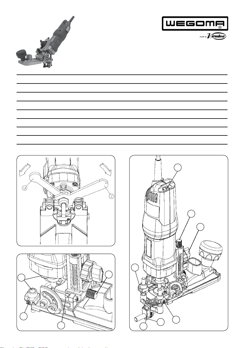
6.2 REGULACIONES DEL CABEZAL
RESPECTO A LA FRESA
Desconectelamáquina de la red eléctrica,
antes de realizar esta operación.
Respecto a la testa de la fresa: El cabezal se situa a la
altura necesaria aflojando el pomo D (Fig. 7), girando
la rueda Y (Fig. 7) hasta alcanzar la posición deseada y
fijándolo en ella con el pomo D (Fig. 7).
El cabezal va provisto además, de un sistema de ajuste
micrométrico de precisión en este eje, para el ajuste fino
de la profundidad de corte, accionado por el husillo A
(Fig. 7). Para usar esta regulación, afloje el pomo D (Figs.
7 y 2) y actúe sobre el husillo A girándolo lentamente
hasta la medida deseada. En el lateral de la máquina
disponede una guiamilimetradade referenciaG1(Fig.7).
Respecto al labio de la fresa: Dispone también de un sis-
tema de ajuste fino de la posición del cabezal, accionado
por el husillo B (Fig. 7). Para usar esta regulación, afloje
el tornillo E (Fig. 7) y actúe sobre el husillo B girándolo
lentamente hasta la posición deseada.
6.3REGULACIÓNDELPALPADORPARA PERFILAR
Desconectelamáquina de la red eléctrica,
antes de realizar esta operación.
Para situar la rulina del palpador a la distancia conve-
niente de la base del cabezal, afloje los tornillos H (Fig.
8), suba o baje el conjunto palpador a la altura deseada
y fíjelos de nuevo en esa posición.
Para situar el corte de la fresa, regule la distancia al
canto de la rulina del palpador, afloje el tornillo M1
(Fig. 8) y ajuste la posición de la rulina con la tuerca de
regulación F (Fig. 8).
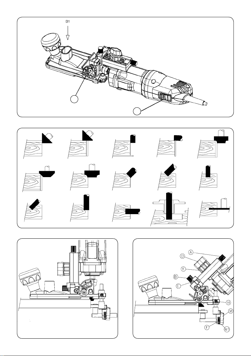
7. PUESTA EN MARCHA
Para la puesta en marcha de la máquina presionar hacia
delante sobre el pulsador R (Fig. 10) el cual quedará
enclavado en posición de marcha. Para parar la máquina
presionarsimplemente sobrelapartetrasera delpulsador
yésteretornaráautomáticamente asu posicióndereposo.
Laregulación electrónica permite trabajar a la velocidad
idónea para cada tipo de trabajo y fresa a utilizar. Para
regular la velocidad, actúe sobre el botón A1 (Fig. 2).
8. APLICACIONES
Las múltiples posibilidades del cabezal abatible y de los
accesorios incluidos permiten a la fresadora KFS135 un
gran número de combinaciones, como perfilar, ranurar,
chaflanar, moldurar, copiar, etc.
8.1 PERFILADO DE LA SUPERFICIE Y
DEL CANTO, CON FRESA CÓNICA DE 90°
Perfilado del recubrimiento de una superficie (Fig.
11-a1), y (Fig. 13):
• Ponga en primer lugar el cabezal a 46° (Fig. 13),
siguiendo las indicaciones del apartado 6.1.
• Afloje el tornillo E (Fig. 13), suba el cabezal justo hasta
el tope superior sin forzarlo, girando el husillo B (Fig. 13)
en sentido horario, y fíjelo de nuevo en esta posición.
• Situe la base del cabezal aproximadamente a la mitad
dellabio de la fresa, aflojando el pomo D(Fig.13)ycon la
ayuda del mando Y y del husillo de ajuste fino A (Fig. 13).
• Coloque el palpador M (Fig. 13) de modo que el ro-
damiento quede cerca de la fresa y fíjelo en la posición
con los tornillos H (Fig. 13).
• Regule la posición del rodamiento, alineándolo con
la fresa, con la ayuda de la tuerca F (Fig. 13) y fije la
posición con el tornillo M1 (Fig. 13).
• Si el tablero es de un aglomerado muy basto, puede
emplear la escuadra lateral de gran superficie de apoyo,
en lugar del palpador de rodamiento y evitará así que
las irregularidades del tablero puedan pasar al perfilado.
• Perfile el sobrante del recubrimiento de la superficie.
Perfilado recto del canto (Fig. 11-b1) y (Fig. 14):
• Afloje el tornillo E (Fig. 14), y baje el cabezal girando
el husillo B (Fig. 14) en sentido anti-horario, hasta que
la base del mismo quede alineada con la fresa y fíjelo de
nuevo en esta posición. Si llega a tope delrecorrido del
husillo B (Fig. 14), y no ha conseguido alinear la fresa
con la base, no fuerce el husillo sobre el tope, afloje el
pomo D (Fig. 14) y haga descender la base del cabezal,
con el husillo A (Fig. 14) hasta conseguirlo.
• Perfile el sobrante del canto.
Perfilado del canto en chaflán:
• Puede perfilar un canto chaflanado en cualquier ángulo
desde 5° a 45°, para lo cual debe aflojar los tornillos N
(Fig. 14) y girar el cuerpo hasta que el ángulo señalado
en el indicador, sea de 45°, más el del chaflán que desea
efectuar, fijando de nuevo los tornillos N.
Ejemplo: para perfilar un chaflán de 30°, deberá inclinar
el cabezal hasta que el indicador señale 75°, o hasta 90°,

14
si el chaflán que desea es de 45°.
• Afloje el tornillo E (Fig. 14), y baje el cabezal girando
el husillo B (Fig. 14) en sentido anti-horario, hasta que
la base del mismo quede aproximadamente a la mitad
del labio de la fresa y fijelo de nuevo en esta posición.
• Regule la posición del rodamiento del palpador, con la
ayudade latuercaF (Fig.13),para obtenerlaprofundidad
de chaflán que desee y fijela con el tornillo M1 (Fig. 13).
• Perfile el chaflán del canto.
8.2 PERFILADO DE LA SUPERFICE
Y DEL CANTO, CON FRESA RECTA D.18
Perfilado del recubrimiento de una superficie (Fig.
11-a2): Coloque en primer lugar la fresa cilíndrica de
D.18, como se indica en el apartado 5.1.
Ponga el motor en posición vertical (Fig. 7), siguiendo
las indicaciones del apartado 6.1.
Situelafresaalaalturanecesaria,accionandolospomos
D e Y y el ajuste fino A (Fig. 7).
Ajuste la altura del palpador M (Fig. 7), hasta que la
rulina quede sobre el canto, y regule la posición de ésta
con la tuerca F (Fig. 7), para que el filo de la fresa quede
enrasado con el borde de la pieza (Fig. 7).
En tablero de aglomerado muy basto, puede emplear la
escuadralateralde gran superficie deapoyo,enlugardel
palpador de rulina y evitará así que las irregularidades
del tablero puedan pasar al perfilado.
Perfile el sobrante del recubrimiento de la superficie.
Perfiladorectodelcanto(Fig. 11-b2):Pongael motora
91,5°(Fig.8), siguiendo lasindicacionesdelapartado6.1.
Situe el filo de la fresa sobre el canto a perfilar (Fig. 9).
Para ello desplace la rulina del palpador M (Fig. 8) hacia
el canto un tramo y acabe de situar la fresa desplazando
el motor en sentido contrario al de la rulina, accionando
la rueda Y y el ajuste fino A (Fig. 8).
Perfile el sobrante del canto.
8.3 PERFILAR EL CANTO CON FRESA DE FORMA
Puede perfilar también el canto en radio (Fig. 12), o
en chaflán (Fig. 11-c-d), desde la posición vertical u
horizontal del motor, si dispone de la fresa del perfil
correspondiente.
8.4 REALIZACION DE CHAFLANES CON FRESA
RECTA
Inclineelmotor a 45° oalángulodeseadoentre 0 y 91.5°,
ajuste el palpador o la escuadra lateral, la profundidad
y proceda al fresado (Fig. 11-f1).
8.5 REALIZACIÓN DE RANURAS
Situela escuadra lateral W (Fig. 5) aladistancia deseada;
ajuste la profundidad de la ranura accionando la rueda
Y y el ajuste fino A (Fig. 5) y proceda a su fresado (Fig.
11-g1-h-i-g2).
8.6 FRESADOS DE COPIAS SOBRE
CUALQUIER PLANTILLA (Fig. 11-j)
Puede fresar copias de una plantilla, montando el
copiador o guía plantilla L (Fig. 4), adecuado a la fresa
que utilice, que se sujeta en la base del cabezal con los
tornillos K (Fig. 4).
Vea las guías plantillas disponibles en el apartado 11
Accesorios Opcionales.
Debe también situar el cabezal en la posición adecuada
para copiar con plantilla, para ello afloje el tornillo E
(Fig. 4), desplace el motor de la máquina hasta el tope X
(Fig. 3), mediante el husillo de ajuste B (Fig. 3), y vuelva
a fijar el pomo E (Fig. 4).
8.7 CORTE O PERFILADO DE CÍRCULOS
Monte el eje para centros en la escuadra lateral, del
modo explicado en el apartado 5.4.
Monte la escuadra en la base de forma invertida, usando
como centro de la circunferencia el eje B3 (Fig. 15).
Ajuste la medida del radio que desea y fíjelo mediante
los tornillos H (Fig. 15).
8.8 PERFILADO DE LOS
EXTREMOS DE UN TABLERO
Se puede perfilar el canto del extremo de una pieza,
apoyando la base de la máquina sobre el canto de la
misma. Para efectuar este perfilado, previamente deberá
montar en la base de la máquina, la tapa de apoyo L1 sumi-
nistrada con el equipo, y fijarla con los tornillos K, (Fig. 19).
9. CONEXIÓN A UNA ASPIRACION EXTERIOR
Para conectar la máquina a los aspiradores AS182K,
AS282K, u otra fuente externa de aspiración, deberá
montarse el acoplamiento de aspiración 6446073 (ac-
cesorio opcional) y conectar la boquilla de goma a la
toma de la máquina B1 (Fig. 10)
10. MANTENIMIENTO ESCOBILLAS Y COLECTOR
Desconectelamáquina de la red eléctrica,
antes de efectuar cualquier operación de
mantenimiento.
Quitar los tornillos R (Fig. 16) que sujetan las tapas
laterales T y separar ambas.
Extraer los portaescobillas S (Fig. 17) con la ayuda de un
pequeño destornillador V, haciendo palanca sobre una
de las pestañas laterales del portaescobillas.
Desplazar hacia atrás el extremo del muelle Q. Retenerlo
en esta posición para extraer la escobilla y sustituirla por
una nueva original Wegoma by Virutex. Colocar de nuevo
el portaescobillas procurando que asiente firmemente

15
en la carcasa y que cada una de las escobillas presionen
suavemente sobre el colector.
Montar las tapas T con sus correspondientes tornillos,
asegurándose de no pellizcar ningún cable en el en-
samblaje de ambas.
Es aconsejable que se tenga en marcha durante unos 15
minutos la máquina una vez cambiadas las escobillas.
Si el colector presenta quemaduras o resaltes, se reco-
mienda hacerlo reparar en un servicio técnico Wegoma
by Virutex.
Mantenga siempre el cable y el enchufe en buenas
condiciones de servicio.
11. ACCESORIOS Y HERRAMIENTAS
Guías para copiar con plantilla (ver Fig. 18)
Referencia Para fresa de Ø A Ø B
2950104 6 mm 8 mm 10 mm
2950105 8 ó 7,6 10 12
2950106 10 mm 12 14
2950107 12 mm 14 16
2950081 14 mm 16 18
2950108 16 mm 18 20
1222084 Pinza Ø 6 mm.
1222085 Pinza Ø 1/4"
1222024 Pinza Ø 8 mm, incluida de origen.
1140087 Fresa de perfilar cónica de 90°, incluida de
origen.
1140016 Fresa de ranurar y perfilar recta D.18, incluida
de origen.
Fresas par aplicaciones varias: Ver página 29
6446073 Acoplamiento de aspiración
Utilizar siempre fresas con el diámetro
de la caña adecuado a la pinza que va
a utilizar y adaptadas a la velocidad de
la màquina.
12. NIVEL DE RUIDO Y VIBRACIONES
Los niveles de ruido y vibraciones de esta herramienta
eléctrica han sido medidos de acuerdo con la Norma
EuropeaEN 60745-2-17 yEN60745-1y sirvencomobase
de comparación con máquinas de semejante aplicación.
El nivel de vibraciones indicado ha sido determinado
para las aplicaciones principales de la herramienta,
y puede ser utilizado como valor de partida para la
evaluación de la exposición al riesgo de las vibraciones.
Sin embargo, el nivel de vibraciones puede llegar a ser
muy diferente al valor declarado en otras condiciones
de aplicación, con otros útiles de trabajo o con un
mantenimiento insuficiente de la herramienta eléctrica
y sus útiles, pudiendo llegar a resultar un valor mucho
más elevado debido a su ciclo de trabajo y modo de
uso de la herramienta eléctrica.
Por tanto, es necesario fijar medidas de seguridad de
protección al usuario contra el efecto de las vibraciones,
como pueden ser mantener la herramienta y útiles de
trabajo en perfecto estado y la organización de los
tiempos de los ciclos de trabajo (tales como tiempos
de marcha con la herramienta bajo carga, y tiempos de
marcha de la herramienta en vacío y sin ser utilizada
realmente ya que la reducción de estos últimos puede
disminuirde formasustancialelvalortotal deexposición).
13. GARANTÍA
Todaslas máquinas electroportátiles WegomabyVirutex
tienen una garantía válida de 12 meses a partir del día
de su suministro, quedando excluidas todas las manipu-
laciones o daños ocasionados por manejos inadecuados
o por desgaste natural de la máquina.
Para cualquier reparación dirigirse al servicio oficial de
asistencia técnica Wegoma by Virutex.
14.RECICLAJEDE LAS HERRAMIENTASELÉCTRICAS
Nunca tire la herramienta eléctrica con el resto de resi-
duos domésticos. Recicle las herramientas, accesorios y
embalajes de forma respetuosa con el medio ambiente.
Respete la normativa vigente de su país.
Aplicable en la Unión Europea y en países europeos
con sistemas de recogida selectiva de residuos:
La presencia de esta marca en el producto o en el
material informativo que lo acompaña, indica que al
finalizar su vida útil no deberá eliminarse junto con
otros residuos domésticos.
Conforme a la Directiva Europea 2002/96/CE los usuarios
puedencontactar conelestablecimientodondeadquirie-
ronel producto,oconlas autoridadeslocalespertinentes,
para informarse sobre cómo y dónde pueden llevarlo
para que sea sometido a un reciclaje ecológico y seguro.
Wegoma by Virutex se reserva el derecho de modificar
sus productos sin previo aviso.

16
ENGLISH
KFS135 TILTABLE TRIMMER
Important
Read these OPERATING INSTRUCTIONS
and the attached GENERAL SAFETY
INSTRUCTIONS LEAFLET carefully before
using the machine. Make sure you have
understood them before operating the
machine for the first time. Keep both
setsof instructions for any futurequeries.
1.SAFETYINSTRUCTIONSFORUSING THE ROUTER
Carefully read the GENERAL SAFETY
INSTRUCTION LEAFLET enclosed with the
machine documents.
2. Before plugging in the machine, make sure that the
power supply voltage is the same as that shown on the
specifications plate.
3. Always keep your hands away from the cutting area.
Always grip the machine safely.
4. Use protective goggles.
5. Always use original Wegoma by Virutex tools. Never
use defective or damaged tools.
6. Always use cutter bits with the appropriate stem
diameter for the chuck collet and tool speed to be used.
Unplug the machine from the power
supply before performing any mainte-
nance operations.
2. SPECIFICATIONS
Inputpower...........................................................................750 W
Universal motor.........................................................50/60 Hz
No-loadspeed...........................................14,000 –30,000/min
Ø max bit..........................................................................25 mm
Østandardchuckcollet..................................................6&8mm
Weight................................................................................2.2 Kg
Weighted equivalent continuous
acousticpressure levelA...................................................83 dBA
Acousticpower levelA......................................................94dBA
Uncertainty......................................................................K= 3dbA
Wear ear protection!
Vibrationtotal values.................................................ah:3.1m/s2
Uncertainty....................................................................K:1.5m/s2
3. STANDARD EQUIPMENT
Insidethe carryingcasethe followingitemswill befound:
• KFS135 Router with 8 mm collet (*)
• Straight cutter for trimming and slotting D.18 LC. 20
• Key: 11 mm for motor shaft.
• Key: 19 mm for chuck collet attachment.
• Copying device
• Bit bearing brake
• Lateral square with centring shaft
• 3-mm Allen wrench
• Operating instructions and other documents
(*) (Machines at 120 V are equipped with 6.35 mm
(1/4") collet.)
4. GENERAL DESCRIPTION OF THE ROUTER
The KFS135 router can be used for trimming laminates,
shaping small mouldings, rabbeting, making straight
cut-outs, chamfering, etc. Its head may be tilted from
0 to 91.5° to cut bevelled edges and chamfer using
cylindrical cutters plus many more applications.
It micrometric copying wheel also allows interior curves
with radii over 52 mm to be cut.
Itcanalsocutcopiesfromtemplatesusingthecopiers or
thetemplateguides shown in section11anditcan cut or
shape circles using the lateral square and centring shaft.
5.ASSEMBLYOFTHEROUTER ANDITSACCESSORIES
5.1 ASSEMBLING AND CHANGING THE CUTTER
Make sure you place the chuck collet in
thecorrect position, otherwisevibrations
may occur or the part itself my come
loose (Fig. 23).
Disconnect the machine from the power
supply before assembly.
To change or assemble a cutter in the machine (Fig.
1), block the motor shaft using the key U, unscrew the
nut using the service key Z, take out the used cutter
and attach the new one placing it into the bottom of
its housing and then tighten using the service keys.
Check that the stem diameter of the
chuck collet matches that of the cutter
stem to be used.
5.2 ASSEMBLING THE FEELER AND BRAKE
Disconnect the machine from the power
supply before assembly.

17
Place copying device set M (Fig. 2), through holes O (Fig.
3) on the head and fix it at the required height using
screws H (Fig. 2).
5.3 ASSEMBLING THE LATERAL SQUARE
Disconnect the machine from the power
supply before assembly.
Place lateral square W (Fig. 5), through holes C (Fig. 4) on
the head and fix it at the required height using screws H.
5.4 ASSEMBLING THE CENTERING DEVICE
Attach the central shaft in the position indicated in Fig.
6, together with the spacer and the stop washer, and
fix them with the nut supplied.
5.5 ASSEMBLING THE BRAKE FOR BIT WITH
BEARINGS
The machine comes with the brake accessory for the
bit with bearings, which prevents the bearing's external
supporttrack with the wood from turning together with
the bit, thus preventing damage to the panel when
trimming the wood.
To attach the brake, proceed in the following manner:
Loosen stud M1 (Fig. 20) and remove the feeler from its
support, unscrewing it completely. Next, fit the brake
assemblyin the support,adjustingitso that rubberspline
R1 is supported on the external bearing track R2 of the
bit, without exerting excessive pressure, as this could
decentre it. (Fig. 21 and 22). Next attach stud M1 again.
6. ADJUSTMENTS
6.1 ADJUSTING HEAD TILT
Disconnect the machine from the power
supply before adjustment.
With the KFS135 router, head tilt may be set for the
cutterheadto be between0and91.5°and may belocked
in any position using screws N (Fig. 7 y 8).
To trim with the 90° conical bit, place the head at 45°
+1° = 46° approximately, to avoid damaging the coating
of the surface when trimming the edge.
Similarly, to trim edges using the D.18 straight bit,
also supplied with the machine, turn the head to the
maximum 91.5°, so that the cutting edge of the bit is
1.5° below the head horizontal (Fig. 9).
6.2 ADJUSTING THE HEAD
WITH REGARD TO THE CUTTER
Disconnect the machine from the power
supply before adjustment.
For the cutter head: The head is set at the required
height by loosening knob D (Fig. 7), turning wheel Y
(Fig. 7) until the required position is reached and it is
then fixed there using knob D (Fig. 7).
The head is also supplied with a high-precision micro-
metric adjustment system on its shaft for making fine
adjustments to cutting depth with screw A (Fig. 7). To
adjust it in this way, loosen knob D (Figs. 7 and 2) and
using screw A slowly turn until the required measure-
ment is obtained. On the side of the machine there is a
reference guide in millimetres G1 (Fig. 7).
For the cutter edge: It also has a fine adjustment system
for the position of the head using screw B (Fig. 7). To
use this adjustment, loosen screw E (Fig. 7) and slowly
turn screw B to the required position.
6.3 AJUSTING THE COPYING SHAFT TO TRIM
Disconnect the machine from the power
supply before adjustment.
In order to set the wheel on the copying device at a
suitable distance from the base of the head, loosen
screws H (Fig. 8), raise or lower the copying device to
the required height and fix it again in this position.
To locate the cutter, set the distance to the edge of the
copying device wheel, loosen screw M1(Fig. 8) and set
the position of the wheel using adjustment nut F (Fig. 8).
7. STARTING
To start the machine, press button R forward (Fig. 10) to
the on position. To stop the machine, simply press the
back of the switch and it will return to the off position.
The electronic control enables you to work at the ideal
speed for each type of job and bit. Adjust the speed
using button A1 (Fig. 2).
8.APPLICATIONS
The many options with the tilting head and the included
accessories give the KFS135 a great deal of versatility
to perform such jobs as trimming, slotting, chamfering,
moulding, copying, etc.
8.1 TRIMMING SURFACES AND EDGES
WITH THE 90° CONICAL BIT
Trimming the coating of a surface (Fig. 11-a1),

18
and (Fig. 13):
• First set the head to 46° (Fig. 13), as described in
section 6.1.
• Loosen screw E (Fig. 13), raise the head so it just reaches
the top limit without forcing, by turning knob B (Fig.
13) clockwise, and fix it in this position.
• Position the base of the head approximately in the
middle of the bit edge by loosening knob D (Fig. 13)
and with the help of control Y and the fine adjustment
knob A (Fig. 13).
• Position feeler M (Fig. 13) so that the bearing is near
the bit and fix it in place using the screws H (Fig. 13).
• Adjust the position of the bearing, aligning it with
the bit, using nut F (Fig. 13) and fix in place with screw
M1 (Fig. 13).
• If the board is made of particularly coarse fibreboard,
youcan use alargesupportsurface lateral squareinstead
of the bearing feeler. This will prevent irregularities in
the board extending to the trim.
• Trim the excess covering from the surface.
Straight edge trimming (Fig. 11-b1) and (Fig. 14):
• Loosen screw E (Fig. 14) and lower the head by turning
knob B (Fig. 14) anti-clockwise, until its base is aligned
with the bit. Then tighten it in the new position. If knob
B (Fig. 14) has been turned as far as it will go and the
bit is still not aligned with the base, do not force the
knob; loosen knob D (Fig. 14) and lower the base of the
head, with knob A (Fig. 14), until aligned.
• Trim the excess edge.
Trimming chamfered edges:
• Chamfered edges may be trimmed to any angle from 5°
to 45°. To do this, loosen the screws N (Fig. 14) and turn
the body to the angle marked on the indicator, i.e. 45°,
plus the required chamfer. Then tighten the screws N.
E.g.: To trim a 30° chamfer, the head must be inclined
until the indicator marks 75°, or 90° for a 45° chamfer.
• Loosen screw E (Fig. 14) and lower the head by turning
knob B (Fig. 14) anti-clockwise, until its base is appro-
ximately in the middle of the bit edge. Then tighten it
in the new position.
• Adjust the position of the feeler bearing, using nut F
(Fig. 13) to obtain the required chamfer depth. Hold in
place with screw M1 (Fig. 13).
• Trim the edge chamfer.
8.2 TRIMMING SURFACES AND EDGES
WITH THE D.18 STRAIGHT BIT
Trimming the coating of a surface (Fig. 11-a2): First
attachthe D.18 cylindricalbit,asdescribed in section5.1.
Attach the required cutter, using knobs D and Y the fine
adjustment A (Fig. 7).
Set the height of copying device M (Fig. 7), until the
wheel is on the edge and fix this position using nut F
(Fig. 7), so that the cutting edge of the cutter is flush
with the edge of the piece (Fig. 7).
With particularly coarse fibreboard, you can use the
large support surface lateral square instead of the
wheel feeler. This will prevent irregularities in the board
extending to the trimming.
Trim the surface coating of the pannel.
Straight edge trimming (Fig. 11-b2): Place the motor at
91.5º (Fig. 8), following the instructions in section 6.1.
Locate the cutting edge on the edge to be trimmed (Fig.
9). To do so, move the wheel on the copying device M
(Fig. 8) to the edge of a section and then locate the
cutter by moving the motor in the opposite direction to
the wheel, using wheel Y and fine adjustment A (Fig. 8).
Trim the rest of the edge.
8.3 TRIMMING EDGES WITH A SHAPED BIT
Edges can also be trimmed at an angle (Fig. 12) or
chamfered (Fig. 11-c-d), from the vertical or horizontal
motorposition,if you havethecorrespondingprofile bit.
8.4 CHAMFERING WITH A STRAIGHT CUTTER
Tilt the motor to 45° or the required angle between 0
and 91.5°, set the copying shaft or lateral square, the
depth and then begin to cut (Fig. 11-f1).
8.5 SLOTTING
Placethe lateralsquareW (Fig.5)at therequireddistance;
set the slot depth by turning wheel Y and fine adjustment
A (Fig. 5) then begin to cut (Fig. 11-g1-h-i-g2).
8.6 CUTTING COPIES WITH
ANY TEMPLATE (Fig. 11-j)
Copies may be cut from a template by mounting a
copier or template guide L (Fig. 4) suitable for the
cutter to be used. This is held on the base of the head
by screws K (Fig. 4).
Please see the available template guide in section 11
Optional Accessories.
The head must also be place in the appropriate position
forcopyingwith a template.Todoso,loosen screw E(Fig.
4), move the machine’s motor until stop X (Fig. 3), using
adjustment screw B (Fig. 3) and tighten knob E (Fig. 4).
8.7 CUTTING OR TRIMMING CIRCLES
Attach the centring shaft on the lateral square as des-
cribed in section 5.4.
Attach the square upside down on the base using shaft
B3 as the centre of the circumference B3 (Fig. 15). Set
the size of the required radius and fix it using screws
H (Fig. 15).
8.8 TRIMMING THE ENDS OF A BOARD
The edges at the end of a piece can be trimmed by
supporting the base of the machine against the edge

19
of this piece. To do this first attach the support cover L1
supplied with the equipment to the base of the machine
and fix it in place with the K screws (Fig. 19).
9. CONNECTING TO EXTERNAL ASPIRATION
Toconnect themachinetoAS182K, AS282Kaspiratorsor
any other external aspiration, the aspiration connector
6446073 (optional accessory) must be attached. Connect
the rubber nozzle to the machine’s socket B1 (Fig. 10)
10. BRUSH AND COLLECTOR MAINTENANCE
Unplug the machine from the electrical
outletbefore carryingoutanymaintenance.
Remove screws R (Fig. 16) holding the side covers T and
separate them.
Remove the brush-holder S (Fig. 17) with small screw-
driver V, using one of the brush-holder side tabs to
lever it out.
Push back the end of spring Q. Keep it in this position
to extract the brush and replace it with a new genuine
Wegoma by Virutex brush. Reinsert the brush-holder,
ensuring that it is firmly positioned in the casing and
that each of the brushes exerts a small amount of
pressure on the collector.
Reattach the covers "T" with the corresponding screws,
making sure that no wires get caught in the process.
It is advisable to allow the machine to run for 15 mi-
nutes in order to ensure that the brushes have properly
settled into place.
If the collector burns or juts out, it should be serviced
by a Wegoma by Virutex service technician.
Keep the cable and plug in good working condition.
11. ACCESSORIES AND TOOLS
Guides to copy with a template (see Fig. 18)
Reference For cutter size Ø A Ø B
2950104 6 mm 8 mm 10mm
2950105 8 or 7.6 10 12
2950106 10 mm 12 14
2950107 12 mm 14 16
2950081 14 mm 16 18
2950108 16 mm 18 20
1222084 Chuck collet Ø 6 mm.
1222024 Chuck collet Ø 8 mm, supplied.
1222085 Chuck collet Ø 1/4"
1140087 90° trimming bit, supplied.
1140016 Straight bit D.18 mm, supplied.
Bits for several jobs: See page 29
6446073 Dust collector connection
Always use bits with the appropriate
shank diameter for the chuck collet and
tool speed to be used.
12. NOISE AND VIBRATION LEVEL
The noise and vibration levels of this device have been
measured in accordance with European standard EN
60745-2-17and EN60745-1andserveas abasisfor com-
parison with other machines with similar applications.
The indicated vibration level has been determined for
the device’s main applications and may be used as an
initial value for evaluating the risk presented by expo-
sure to vibrations. However, vibrations may reach levels
that are quite different from the declared value under
other application conditions, with other tools or with
insufficient maintenance of the electrical device or its
accessories, reaching a much higher value as a result
of the work cycle or the manner in which the electrical
device is used.
Therefore, it is necessary to establish safety measures
to protect the user from the effects of vibrations, such
as maintaining both the device and its tools in perfect
condition and organising the duration of work cycles
(such as operating times when the machine is subjected
toloads, andoperatingtimeswhenworking withno-load,
in effect, not in use, as reducing the latter may have a
considerable effect upon the overall exposure value).
13. WARRANTY
All Wegoma by Virutex power tools are guaranteed for
12 months from the date of purchase, excluding any
damage which is a result of incorrect use or of natural
wear and tear on the machine. All repairs should be
carried out by the official Wegoma by Virutex technical
assistance service.
14. RECYCLING ELECTRICAL EQUIPMENT
Neverdispose ofelectricalequipmentwithdomestic was-
te. Recycle equipment, accessories and packaging in ways
that minimise any adverse effect on the environment.
Comply with the current regulations in your country.
Applicable in the European Union and in European
countries with selective waste collection systems:
If this symbol appears on the product or in the accom-
panying information, at the end of the product's useful
lifeit must notbedisposedof withotherdomesticwaste.

20
In accordance with European Directive 2002/96/EC, users
maycontact theestablishmentwhere theypurchasedthe
productor the relevant local authority to find outwhere
and how they can take the product for environmentally
friendly and safe recycling.
Wegoma by Virutex reserves the right to modify its
products without prior notice.
FRANÇAIS
AFFLEUREUSE INCLINABLE KFS135
Important
Avant d'utiliser la machine, lisez attenti-
vementceMANUELD'INSTRUCTIONSetla
BROCHURED'INSTRUCTIONSGÉNÉRALES
DE SÉCURITÉ qui vous sont fournis avec
cette machine. Assurez-vous de bien
avoir tout compris avant de commencer
à travailler sur la machine.
Gardez toujours ces deux manuels
d'instructions à portée de la main pour
pouvoir les consulter, en cas de besoin.
1. INSTRUCTIONS DE SÉCURITÉ
POUR LE MANIEMENT DE L'AFFLEUREUSE
Lire attentivement le MANUEL
D’INSTRUCTIONS GÉNÉRALES DE SÉ-
CURITÉ joint à la documentation de la
machine.
2. Avant de brancher la machine, vérifier si la tension
d’alimentation correspond à celle indiquée sur la plaque
de caractéristiques.
3. Toujours maintenir les mains éloignées de la zone de
coupe. Toujours fixer fermement la machine.
4. Utiliser des lunettes de protection.
5. Toujours utiliser des outils d'origine Wegoma by
Virutex. Ne jamais utiliser d'outils défectueux ou en
mauvais état.
6. Toujours utiliser des fraises au diamètre correct pour
la pince et adaptées à la vitesse de la machine.
Débrancher la machine du secteur
avant de procéder à toute opération de
maintenance.
2. CARACTÉRISTIQUES
Puissance.............................................................................750W
Moteuruniversel............................................................50/60 Hz
Vitesseà vide..............................................14.000– 30.000/min
Øfraise max.........................................................................25mm
Øpincestandard.............................................................6et 8mm
Poids........................................................................................2,2kg
Niveau de pression acoustique
continuéquivalentpondéréA..........................................83dBA
NiveaudepuissanceacoustiqueA..................................94dBA
Incertitude......................................................................K= 3dbA
Porter une protection acoustique!
Valeurstotalesdesvibrations.....................................ah: 3,1m/s2
Incertitude....................................................................K:1,5 m/s2
3. ÉQUIPEMENT STANDARD
La mallette contient les éléments suivants:
• Fraiseuse KFS135 avec pince de 8 mm
• Fraise droite pour affleurer et rainurer D.18 LC. 20
• Clef o/c: 11 mm pour arbre moteur.
• Clef o/c: 19 mm pour écrou fixation pince.
• Palpeur
• Frein roulement fraise
• Équerre latérale avec axe pour centres
• Clef six pans o/c 3 mm
• Manuel d'instructions et documentation variée
4. DESCRIPTION GÉNÉRALE DE LA FRAISEUSE
Les fonctions de la fraiseuse KFS135 sont l'affleurage
de stratifiés, la réalisation de petites moulures, de
délardements, de rainures droites, de chanfreins, etc.
Sa tête rabattable de 0 à 91,5° permet également de
faire des rainures en biseaux, de réaliser des chanfreins
en utilisant des fraises cylindriques et de multiples
applications additionnelles.
Son palpeur à galet à réglage micrométrique lui permet
aussi de profiler des courbes intérieures d'un rayon
supérieur à 52 mm.
Elle peut également fraiser des copies de gabarit en
utilisant les copieurs ou guides gabarits indiqués au
paragraphe 11 et couper ou profiler des cercles à l’aide
de son équerre latérale et de son axe pour centres.
5. MONTAGE DE LA FRAISE ET DES ACCESSOIRES
5.1 MONTAGE ET CHANGEMENT DE LA FRAISE
Assurez vous de bien monter la pince
porte-fraise dans la position correcte,
sinon cela pourrait entraîner des
vibrations ou même le détachement de
celui-ci de son support (Fig. 23).
Table of contents
Languages:
Other Virutex Trimmer manuals

Virutex
Virutex RMV70U User manual

Virutex
Virutex PL11 User manual

Virutex
Virutex AS93 User manual

Virutex
Virutex FR256N User manual

Virutex
Virutex FR217S User manual

Virutex
Virutex FR217S User manual

Virutex
Virutex FR1217T User manual

Virutex
Virutex WEGOMA KFR130N User manual

Virutex
Virutex FR56E User manual

Virutex
Virutex RC321S DOBLE User manual

Virutex
Virutex PAE85T User manual

Virutex
Virutex FR1192T User manual

Virutex
Virutex FR1156T User manual

Virutex
Virutex FR1292T User manual

Virutex
Virutex RC421 User manual

Virutex
Virutex FR192N User manual

Virutex
Virutex FR292R User manual

Virutex
Virutex FR1817T User manual

Virutex
Virutex Wegoma KG30 User manual

Virutex
Virutex FR156N User manual