manuals.online logo
Brands
  1. Home
  2. •
  3. Brands
  4. •
  5. Vision
  6. •
  7. Accessories
  8. •
  9. Vision ZD2301IN-5 User manual

Vision ZD2301IN-5 User manual

Installation & Operation Manual
ZD2301IN-5
ZD2301MY-5
ZD2301EU-5
ZD2301RU-5
ZD2301US-5
ZD2301IL-5
ZD2301KR-5
ZD2301HK-5
ZD2301JP-5
ZD2301BR-5
Wireless 4 IN 1 Multi-Sensor
(Dry Contact, Humidity, Temperature & Light)
ZD 2301
V0
1040508
6B1Z-23001
Introduction
Thanks for choosing the Vision’s wireless 4 in 1 Multi-Sensor (door window contact sensor,
humidity sensor, temperature sensor, and light sensor) of the home security device. This sensor
is a Z-Wave™ enabled device (interoperable, two-way RF mesh networking technology) and is
fully compatible with any Z-Wave™ enabled network and its security framework. Every main
powered Z-Wave enabled device acts as a signal repeater and multiple devices result in more
possible transmission routes which helps eliminate “RF dead-spots”
Z-Wave™ enabled devices displaying the Z-Wave™ logo can also be used with it regardless of
the manufacturer, and ours can also be used in other manufacturer’s Z-Wave™ enabled
networks. This multi-sensor sends Z-Wave™ signal when door or window is opened and closed
or humidity, temperature, luminous change. When the device is secure included into Z-Wave
network, above communication will be encrypted. Security enabled_ Z-Wave controller must be
used to fully utilize the product.
Product Description and Specification
*** For indoor use only***
Specification:
Package
Content:
Protocol: Z-Wave™ (ZM5202)
Frequency Range:
865.22MHz (ZD2301IN-5)
868.10MHz (ZD2301MY-5)
868.42MHz (ZD2301EU-5)
869.00MHz (ZD2301RU-5)
908.42MHz (ZD2301US-5)
916.00MHz (ZD2301IL-5)
919~923MHz (ZD2301KR-5)
919.80MHz (ZD2301HK-5)
922~926MHz (ZD2301JP-5)
921.42MHz (ZD2301BR-5)
Operating Range: Up to 100 feet line of sight
Operating Temp.: -15°C~ 60°C (5°F ~140°F)
Battery: CR14250 Battery * 1PC
1pc
1pc
1pc
2pcs
2pcs
1pc
1pc
ZD 2301-5 sensor
Bracket for Magnet
Magnet
Screw to fix magnet
Adhesive tape for Magnet /
sensor
Battery: CR14250 Battery
Installation & Operation manual
Z-Wave Command Classes:
COMMAND_CLASS_ASSOCIATION_GRP_INFO
COMMAND_CLASS_ASSOCIATION_V2
COMMAND_CLASS_BATTERY
COMMAND_CLASS_CONFIGURATION
COMMAND_CLASS_DEVICE_RESET_LOCALLY
COMMAND_CLASS_FIRMWARE_UPDATE_MD_V2
COMMAND_CLASS_MANUFACTURER_SPECIFIC_V2
COMMAND_CLASS_NOTIFICATION_V4
COMMAND_CLASS_POWERLEVEL
COMMAND_CLASS_SECURITY
COMMAND_CLASS_SENSOR_MULTILEVEL_V7
COMMAND_CLASS_VERSION_V2
COMMAND_CLASS_WAKE_UP_V2
COMMAND_CLASS_ZWAVEPLUS_INFO_V2
Notification V4 Type
SWITCH TYPE
STATUS
Notification Type
Reed Switch 0x06
Tamper Switch
0x07
Event
Reed Switch Close: 0x17, Open: 0x16
Tamper Switch
Close:0x00; Open:0x03
V1 Alarm:
Configuration -Temperature
Parameter
Number Size VALUE Preset
1 1 °C 0x00 °C(0x00)
°F 0x01
2 1 1~50 (Set up from 0.1°C~5°C) 1 (
°
C)
Switch Type Status
Alarm Type
Reed Switch 0x06
Tamper Switch 0x07
Alarm Level Close: 0x00; Open 0xFF
-1- -2-
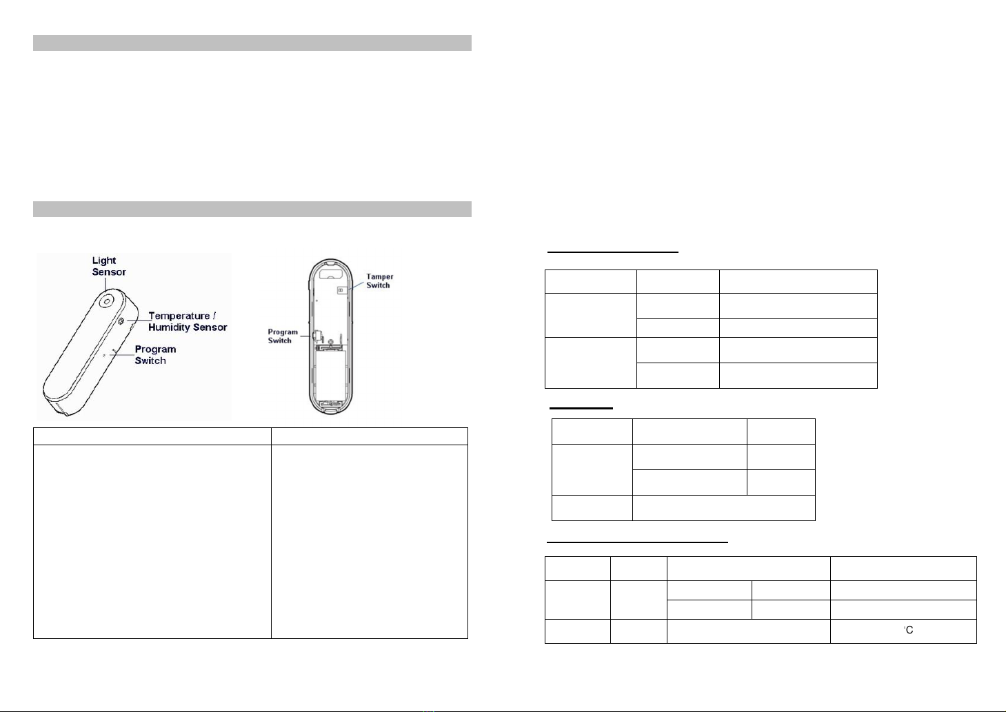
Configuration – Humidity
Parameter
Number Size VALUE Preset
3 1 1~50 (Set up from 1%~50%)
10%
Configuration – Light
Parameter
Number Size VALUE Preset
4 1 0,5~50 (Set up from 0 for Off
or 5%~50%) 10%
Installation
Notice: If you are installing the entire Z-Wave™ system for the first time, please refer to
the installation guide of Z-Wave™ Interface Controller before installing ZD2301.
1. Push release button to open the rear cover.
2. Using adhesive tape to affix the rear cover on the frame along the opening edge of
door / window.
3. Insert CR14250 battery *1 into the battery compartment, if user press the program
switch, ZD2301 will send the NIF. ZD2301 will go to sleep if user didn’t press the
program switch within 20 seconds.
LED Status for Z-Wave Network:
* If user presses the program switch, the red LED will flash 5 times if the ZD2301 has
not been included yet.
* If user presses the program switch, the red LED will flash 1 time if the ZD2301 has
been included.
4. For “Inclusion” in (adding to) a network: Put the Z-Wave™ Interface Controller into
“inclusion” mode, and following its instruction to add the ZD2301 to your controller. To
get in the “inclusion” mode, the distance between sensor and controller is suggested
to be in one meter. Press the program switch of ZD2301 for sending the NIF. After
sending NIF, Z-Wave will send the auto inclusion; otherwise, ZD2301 will go to sleep
after 20 seconds.
5. For “Exclusion” from (removing from) a network: Put the Z-Wave™ Interface
Controller into “exclusion” mode, and following its instruction to delete the ZD2301
from your controller. Press the program switch of ZD2301 for 1 second at least to be
excluded.
Note: All user and network settings will be cleared and the device reset to factory
defaults when the device is excluded.
6. Push back the rear cover, the LED should go off.
7. Fix the Magnet by using the adhesive tape; locate the Magnet close to the ZD2301
sensor the distance between these two devices should be in 1.9cm. Make sure the
location of device without shelter above or block the sensor area.
8. Awake Mode:
Press the Program SW, the LED will flash one time and ZD2301 will send “Wake Up
Notification” after 5 seconds. If ZD2301 received “Wake Up No More Information”
command then the ZD2301 will go to sleep or it will wait 10 seconds then go to sleep.
It will precede all the commands after sending the “Wake Up Notification”
9. Auto Wake Up:
Use “Wake Up” command to set up the awaking time and send the wake up
notification to controller. User can use command to change the auto wake up from
10 minutes to 1 week, Interval increment is 3 minutes.
10.Battery Capacity Detection:
* Use “Battery Get” command to have the battery capacity back in %
* It will detect the battery capacity automatically
* Low Battery Auto Report (low battery is set as 2.6+/-0.1 Voltage, detects every 2
hours)
11.Association:
* Support grouping identifier=1, one group with 5 nodes,
* Association is used for other grouping devices chain reaction.
* All triggering reports & low voltage report will be sent to the associated nodes
12.Power Level Control:
* Use “Power Level Set” to set up the RF strength
* Use “Power Level Test Node Set” to test specific node’s RF sensitivity
13.Support Explorer Frame Function
14.All the rest commands depend on Z-Wave standard
15.Factory Default Reset:
*Open the rear cover to send the Alarm Report and then press the program switch 10
times in 10 seconds, ZD2301 will send the “Device Reset Locally” command and reset to
the factory default.
* Please use this procedure only in the event that the network primary controller is
missing or otherwise inoperable.
-3-
Operation
1. Opening/Closing the door/window to separate the magnet from the sensor will send
signal to any association nodes according to the Status/Signal table on page 2and
the LED will flash once.
2. When ZD2301 no trigger, the LED will flash every minute to show the color of
temperature.
3. If the cover of sensor is removed, the tamper switch will send signal according the
Status/Signal table, and the LED will flash once. ZD2301 will send signal according
the status / signal table after closing the rear cover back 2 seconds.
4. Temperature-If the present temperature is different with the sensor record and
exceed the setting program, the sensor will report the present temperature. LED
flash every minute to represent the temperature or wake up by press the Program
SW.
Temperature LED Color
Under 15°C Green
15~23°C Blue
23~28°C Yellow
28~36°C Orange
Over 36°C Red
Multilevel Sensor Report
Sensor Type 0x01
Scale 0x00 (°C)
0x01 (°F)
Size and Precision 2
5. Humidity Report-
If the present humidity is different with the sensor record and
exceed the setting program, the sensor will report the present humidity.
Multilevel Sensor Report
Sensor Type 0x05
Scale 0x00 (%)
Size and Precision 2
6. Light Report-
If the present illumination is different with the sensor record and
exceed the setting program, the sensor will report the present illumination.
Multilevel Sensor Report
Sensor Type 0x03
Scale 0x00 (%)
Size and Precision 2
Federal Communications Commission Statement
This equipment has been followed to comply with the limits for a Class B digital device,
pursuant to Part 15 of the FCC Rules. These limits are designed to provide reasonable
protection against harmful interference in a residential installation. This equipment
generates, uses and can radiate radio frequency energy and, if not installed and used in
accordance with the instruction, may cause harmful interference to radio communications.
However, there is no guarantee that interference will not occur in a particular installation.
If this equipment does cause harmful interference to radio or television reception, which
can be determined by turning the equipment off and on, the user is encouraged to try and
correct the interferene by one of the following measures:
-Reorient or relocate the receiving antenna,
-Increase the separation between the equipment and receiver,
-Connect the equipment into and outlet on a circuit different from that to which the
receiver is connected.
Consult the dealer or an experienced radio/TV technician for help.
This device complies with Part 15 of the FCC Rules. Operation is subject to the following
two conditions: (1) this device may not cause harmful interference, and (2) this device
must accept any interference received, including interference that may cause undersired
operation.
FCC Caution: Any changes or modifications not expressly approved by the party
responsible for compliance could void the user’s authority to operate this equipment.
Limited Warranty
Vision Guarantees that every wireless 4-in-1 multi sensor is free from physical defects in
material and workmanship under normal use for one year from the date of purchase. If
the product proves defective during this one-year warranty period, Vision will replace it
free of charge. Vision does not issue any refunds. This warranty is extended to the
original end user purchase only and is not transferable. This warranty does not apply to:
(1) damage to units caused by accident, dropping or abuse in handling, or any negligent
use; (2) units which have been subject to unauthorized repair, taken apart, or otherwise
modified; (3) units not used in accordance with instruction; (4) damages exceeding the
cost of the product; (5) transit damage, initial installation costs, removal cost, or
reinstallation cost. For information on additional devices, please visit us at
www.visionsecurity.com.tw
-5-
-6-

This manual suits for next models

9

Other Vision Accessories manuals

Vision ZP3113IN-7 User manual

Vision

Vision ZP3113IN-7 User manual

Vision ZD2106IN-7 User manual

Vision

Vision ZD2106IN-7 User manual

Vision ZA1501IN-5 User manual

Vision

Vision ZA1501IN-5 User manual

Vision TC-HDMI12 User manual

Vision

Vision TC-HDMI12 User manual

Vision ZD2112IN-5 User manual

Vision

Vision ZD2112IN-5 User manual

Vision ZF 5201 IN User manual

Vision

Vision ZF 5201 IN User manual

Vision ZD2106IN-7 User manual

Vision

Vision ZD2106IN-7 User manual

Vision ZD2102IN-5 User manual

Vision

Vision ZD2102IN-5 User manual

Vision ZD 2102 EU User manual

Vision

Vision ZD 2102 EU User manual

Vision ZD2102IN-8 User manual

Vision

Vision ZD2102IN-8 User manual

Vision ZP3111IN-5 User manual

Vision

Vision ZP3111IN-5 User manual

Vision ZP3113IN-7 User manual

Vision

Vision ZP3113IN-7 User manual

Vision ZD2105IN-5 User manual

Vision

Vision ZD2105IN-5 User manual

Vision ZD2201IN-5 User manual

Vision

Vision ZD2201IN-5 User manual

Vision ZD 2102 EU User manual

Vision

Vision ZD 2102 EU User manual

Vision ZF 5201 IN-5 User manual

Vision

Vision ZF 5201 IN-5 User manual

Popular Accessories manuals by other brands

Toto Sound Experience THU9201 instruction manual

Toto

Toto Sound Experience THU9201 instruction manual

HoMedics Aroma ARMH-340 instruction manual

HoMedics

HoMedics Aroma ARMH-340 instruction manual

QNect QN-WD01 installation guide

QNect

QNect QN-WD01 installation guide

DRY AGER DX 500 user manual

DRY AGER

DRY AGER DX 500 user manual

Coleman POWERCHILL 5644 Instructions for use

Coleman

Coleman POWERCHILL 5644 Instructions for use

Baumer FKDM 22P1902/S14F user manual

Baumer

Baumer FKDM 22P1902/S14F user manual

AND Weighing Indicator AD-4329 OP-02 instruction manual

AND

AND Weighing Indicator AD-4329 OP-02 instruction manual

Rittal SK 3303.470 Assembly and operating instructions

Rittal

Rittal SK 3303.470 Assembly and operating instructions

AEG BK 6 Instructions for use

AEG

AEG BK 6 Instructions for use

Galeo SYRMA Instructions for use

Galeo

Galeo SYRMA Instructions for use

Dynatron iKom operating instructions

Dynatron

Dynatron iKom operating instructions

OmieLife OMIEBOX user manual

OmieLife

OmieLife OMIEBOX user manual

Kompernass KAA 31 A1 operating instructions

Kompernass

Kompernass KAA 31 A1 operating instructions

Manning VL-F7-N4-LPA-MK Instruction and installation manual

Manning

Manning VL-F7-N4-LPA-MK Instruction and installation manual

KRAFTWERK 506.000.100 user manual

KRAFTWERK

KRAFTWERK 506.000.100 user manual

Enabling Technologies DYNAMIQUE owner's manual

Enabling Technologies

Enabling Technologies DYNAMIQUE owner's manual

Balluff BTL6-Ax1 Series user guide

Balluff

Balluff BTL6-Ax1 Series user guide

Hunter LIT-293 manual

Hunter

Hunter LIT-293 manual

manuals.online logo
manuals.online logoBrands
  • About & Mission
  • Contact us
  • Privacy Policy
  • Terms and Conditions

Copyright 2025 Manuals.Online. All Rights Reserved.