BEDIENUNGSANLEITUNG www.voltcraft.de
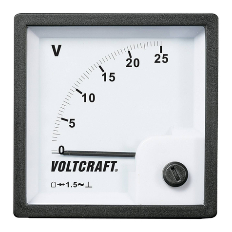
Dreheisen-Einbauinstrument
Klasse 2,0
Best.-Nr. 12 95 18 1A
Best.-Nr. 12 95 34 5A
Best.-Nr. 12 95 42 10A
Best.-Nr. 12 95 69 15A
Best.-Nr. 12 95 85 25A
Best.-Nr. 12 95 93 40V
Best.-Nr. 12 96 07 100V
Best.-Nr. 12 96 15 300V
Bestimmungsgemäße Verwendung
Dreheisen-Einbauinstrumente zum Einbau in Schaltschränke oder Anzeigetafel.
Der Anschluss erfolgt direkt ohne externe Bauteile; Die entsprechenden Vorwiderstände/Stromshunt´s sind
bereits integriert.
Sie dürfen nur im eingebauten Zustand in Betrieb genommen werden. Die entsprechenden Vorschriften
müssen beachtet werden.
Die Einbauinstrumente sind mit verschiedenen Messbereichen erhältlich.
Der Skalenzeiger kann an der frontseitigen Schraube feinjustiert werden.
Eine Skalenbeleuchtung ist nachrüstbar. Die Steckfassungen und Anschlüsse sind bereits vorbereitet.
Beachten Sie die entsprechenden technischen Daten
Eine Verwendung in Feuchträumen oder im Freien ist nicht zulässig.
Das gesamte Produkt darf nicht geändert bzw. umgebaut werden!
Der Einbau und die Installation darf nur durch eine Fachkraft erfolgen, welche mit den erforderlichen
Vorschriften und möglichen Gefahren vertraut ist
Die Sicherheitshinweise sind unbedingt zu beachten!
Sicherheits- und Gefahrenhinweise
Ein in einem Dreieck bendliches Ausrufezeichen weist auf wichtige Hinweise in der
Bedienungsanleitung hin. Lesen Sie bitte vor Inbetriebnahme die komplette Anleitung
durch, sie enthält wichtige Hinweise zum korrekten Betrieb. Bei Schäden, die durch
Nichtbeachten der Anleitung verursacht werden, erlischt der Garantieanspruch! Für
Folgeschäden übernehmen wir keine Haftung!
Ein Blitzsymbol im Dreieck warnt vor einem elektrischen Schlag oder der Beeinträchtigung
der elektrischen Sicherheit des Geräts.
Aus Sicherheits- und Zulassungsgründen ist das eigenmächtige Umbauen und/oder Verändern des Gerätes
nicht gestattet.
Amperemeter nur anwendbar in den Stromkreisen <75VDC or <50VAC.
Das Produkt ist kein Spielzeug und gehört nicht in Kinderhände!
Lassen Sie das Verpackungsmaterial nicht achtlos liegen. Dieses könnte für Kinder zu einem gefährlichen
Spielzeug werden.
In gewerblichen Einrichtungen sind die Unfallverhütungsvorschriften des Verbandes der gewerblichen
Berufsgenossenschaften für elektrische Anlagen und Betriebsmittel zu beachten.
Die Einbauinstrumente dürfen nicht für medizinische Zwecke eingesetzt werden.
Seien Sie besonders Vorsichtig beim Umgang mit Spannungen größer 25V~ bzw. 35VDC. Bereits bei diesen
Spannungen können Sie bei Berührung elektrischer Leitungen einen lebensgefährlichen elektrischen
Schlag erhalten.
Ein Betrieb unter widrigen Umgebungsbedingungen ist nicht zulässig. Widrige Umgebungsbedingungen
sind: Nässe oder zu hohe Luftfeuchtigkeit
Staub und brennbare Gase, Dämpfe oder Lösungsmittel
Wenn anzunehmen ist, dass ein gefahrloser Betrieb nicht mehr möglich ist, so ist das Gerät außer Betrieb
zu setzen und gegen unbeabsichtigten Betrieb zu sichern.
Es ist anzunehmen, dass ein gefahrloser Betrieb nicht mehr möglich ist, wenn:
das Gerät sichtbare Beschädigungen aufweist,
das Gerät nicht mehr arbeitet und
nach längerer Lagerung unter ungünstigen Verhältnissen oder
nach schweren Transportbeanspruchungen.
Symbolerklärung
Am Skalenblatt sind verschiedene Symbole angebracht, welche folgende Bedeutung haben:
Einbaulage senkrecht
Genauigkeitsklasse bezogen auf den Skalenendwert
Wechselspannung/-strom (AC)
Gleichspannung/-strom (DC)
Dreheisenmesswerk
Isolationsspannung;
Die Zahl im Stern zeigt die Isolationsspannung x1000V an
•
•
•
•
•
•
Version 01/06Version 01/06
Einbau
Montieren Sie das Einbauinstrument mit den beiliegenden Montageschrauben in eine vorgefertigte
Frontplattenöffnung. Befestigen Sie das Panelmeter sorgfältig.
Die entsprechenden Abmessungen (in mm) können Sie folgender Skizze entnehmen. Die
Befestigungsschrauben haben das Maß M3.
A B C D E F G H I J
70 60 12 10 23 51 6 48 48 30
Anschluss
Um eine sachgemäße Inbetriebnahme zu gewährleisten, lesen Sie vor Gebrauch unbedingt
diese Bedienungsanleitung mit den Sicherheitshinweisen vollständig und aufmerksam
durch!
Vor dem Abnehmen einer Abdeckung muss das Messinstrument und alle weiteren
angeschlossenen Teile stromlos geschalten werden. Es besteht die Gefahr eines
lebensgefährlichen elektrischen Schlages!
Der Anschluss der Spannungsmessinstrumente erfolgt mittels Parallelschaltung.
Der Anschluss der Strommessinstrumente erfolgt mittels Reihenschaltung.
Schließen Sie das Instrument an den beiden rückseitigen Schraubklemmen wie abgebildet an.
Parallelschaltung für V Reihenschaltung für A
Der Anschluss der optionalen Skalenbeleuchtung erfolgt an den beiden Lötfahnen.
Zum Einsetzen möglicher Skalenlämpchen nehmen Sie die frontseitige Instrumentenabdeckung vorsichtig
ab und entfernen das Skalenblatt.
Setzen Sie zwei passende Lämpchen ein und verschrauben bzw. verschließen das Einbauinstrument wie
der vorsichtig.
Achten Sie darauf, dass der Skalenzeiger nicht verbogen wird.
Technische Daten
Best.-Nr. Messbereich Messwerk Genauigkeit Innenwiderstand
12 95 18 1A Dreheisen 2,0% 1,1 Ohm
12 95 34 5A Dreheisen 2,0% 1,1 Ohm
12 95 42 10A Dreheisen 2,0% 1,1 Ohm
12 95 69 15A Dreheisen 2,0% 1,1 Ohm
12 95 85 25A Dreheisen 2,0% 1,1 Ohm
12 95 93 40V Dreheisen 2,0% 740 Ohm
12 96 07 100V Dreheisen 2,0% 4,5 kOhm
12 96 15 300V Dreheisen 2,0% 12,3 kOhm
Umgebungsbedingungen
Arbeitstemperaturbereich. . . . . . . . . . . . . . : –25°C bis +55°C
OPERATING INSTRUSTIONS www.voltcraft.de
Moving iron panelmeter
class 2.0
Item No. 12 95 18 1A
Item No. 12 95 34 5A
Item No. 12 95 42 10A
Item No. 12 95 69 15A
Item No. 12 95 85 25A
Item No. 12 95 93 40V
Item No. 12 96 07 100V
Item No. 12 96 15 300V
Intended use
Moving coil panelmeter for installation in switch cabinets or display panels.
The installation occurs directly without external components; pre-resistors are already integrated in the
circuit!
Only in integrated status they may be put into operation. The suitable regulations are to be observed.
The panelmeter are available with different measurement ranges.
The scale needle can be adjusted precisely with the front screw.
A scale lighting is retrofit. The plug sockets and connections are already prepared.
Observe the technical data for this!
The device must not be used in damp interiors or outdoors in the open air.
No part of the product may be modified or converted!
Assembly and installation may only be carried out by a specialist, who is familiar with the relevant regula
tions and the ensuing risks.
The safety instructions should be observed without fail!
Safety Instructions and Hazard Warnings
The exclamation mark in the triangle indicates that the information provided next to it is
of particular importance in the operating instructions. Please read the complete operating
instructions before use. They contain important information for correct operation. The
warranty will lapse for damage due to non-compliance with these instructions. We shall
not be held liable for any consequential damage or loss!
The lightening symbol in a triangle warns against an electric shock or the impairment of
the electrical safety of the appliance.
For safety and licensing reasons (CE), unauthorised conversion and/or modification of the device is not
permitted.
The amperemeters only applicable in circuits <75VDC or <50VAC.
The device is not a toy and has no place in the hands of children.
Do not leave packaging material lying around carelessly. This could become a dangerous toy in the hands
of children.
In commercial institutions, the accident prevention regulations of the Employer’s Liability Insurance
Association for Electrical Systems and Operating Materials are to be observed.
The panelmeter may not be used for medical purposes.
Take particular care when dealing with voltages exceeding 25V~ and 35VDC. Even at this voltage, it is
possible to receive a fatal electric shock if you touch electric conductors.
Operation is impermissible under unfavourable ambient conditions. The following are unfavourable ambient
conditions:
damp or humidity which is too high
dust or combustible gases, vapours or solvents
If you have reasons to assume that safe operation is no longer possible, then disconnect the appliance
immediately and secure it against inadvertent operation.
It can be assumed that safe operation is no longer possible if:
the appliance is visibly damaged,
it does not function any longer and
the appliance has been stored for long periods of time under unfavourable conditions or
the appliance has been subject to considerable stress in transit.
Explanations of symbols
At the scale’s face different symbols are attached, that have the following significance:
installation position vertical
accuracy class related to the scale end value
alternating voltage/-current (AC)
direct voltage/-current (DC)
moving iron instrument
isolation voltage;
star’s figure displays isolation voltage x1000V
•
•
•
•
•
•
Version 01/06Version 01/06
Installation
Mount the panelmeter with the supplied assembly screws into the prefabricated front plate opening. Fasten
the panel meter carefully.
You find the appropriate measurements (in mm) in the figure below.The fastening screws measure M3.
A B C D E F G H I J
70 60 12 10 23 51 6 48 48 30
Connection
In order to ensure a correct start of operation, you should read these operating instructions
including the safety instructions thoroughly and attentively before using the device.
Before removing a cover the meter and all other connected parts must be switched-off.
There is risk of a fatal electric shock!
Via a parallel connection the voltage meters are connected.
Via a series connection the current meters are connected.
Connect the panelmeter an both screw terminals on the rear as illustrated.
Parallel connection for V Serial connection for A
The connection of optional scale lighting occurs via the two soldering lugs.
For inserting possible scale lamps, carefully remove the front cover of the panelmeter and take off the sca
le face.
Insert two fitting lamps and screw together and close, respectively, the panelmeter carefully. Take care that
the scale needle is not bent.
Technical Data
Item-No. Measuring area Movement Accuracy Internal resistance
12 95 18 1A Moving iron 2.0% 1.1 Ohm
12 95 34 5A Moving iron 2.0% 1.1 Ohm
12 95 42 10A Moving iron 2.0% 1.1 Ohm
12 95 69 15A Moving iron 2.0% 1.1 Ohm
12 95 85 25A Moving iron 2.0% 1.1 Ohm
12 95 93 40V Moving iron 2.0% 740 Ohm
12 96 07 100V Moving iron 2.0% 4.5 kOhm
12 96 15 300V Moving iron 2.0% 12.3 kOhm
Ambient Conditions
Working temperature range. . . . . . . . . . . . . . : –25°C to +55°C
Diese Bedienungsanleitung ist eine Publikation von Voltcraft®, Lindenweg 15,
92242 Hirschau, Tel.-Nr. 0180/ 586 582 723 8.
Diese Bedienungsanleitung entspricht dem technischen Stand bei Drucklegung.
Änderung in Technik und Ausstattung vorbehalten.
© Copyright 2005 by Voltcraft®. 2006/01/RC.
These operating instructions are published by Voltcraft®, Lindenweg 15, 92242
Hirschau/ Germany, Phone +49 180 586 582 723 8.
The operating instructions reflect the current technical specifications at time of
print. We reserve the right to change the technical or physical specifications.
© Copyright 2005 by Voltcraft®. 2006/01/RC.
