Volvo D12 User manual

Service Manual
Trucks
Group 250–600
Intake and Exhaust System
D12, D12A, D12B, D12C
PV776-TSP144524

Foreword
The descriptions and service procedures contained in this manual are based on de-
signs and methods studies carried out up to August 2000.
The products are under continuous development. Vehicles and components produced
after the above date may therefore have different specifications and repair methods.
When this is believed to have a significant bearing on this manual, supplementary ser-
vice bulletins will be issued to cover the changes.
The new edition of this manual will update the changes.
In service procedures where the title incorporates an operation number, this is a refer-
ence to an S.R.T. (Standard Repair Time).
Service procedures which do not include an operation number in the title are for gen-
eral information and no reference is made to an S.R.T.
The following levels of observations, cautions and warnings are used in this Service
Documentation:
Note: Indicates a procedure, practice, or condition that must be followed in order to
have the vehicle or component function in the manner intended.
Caution: Indicates an unsafe practice where damage to the product could occur.
Warning: Indicates an unsafe practice where personal injury or severe damage to the
product could occur.
Danger: Indicates an unsafe practice where serious personal injury or death could oc-
cur.
Volvo Trucks North America, Inc.
Greensboro, NC USA
Order number: PV776-TSP144524
© 2000 Volvo Trucks North America, Inc., Greensboro, NC USA
All rights reserved. No part of this publication may be reproduced, stored in
retrieval system, or transmitted in any forms by any means, electronic, me-
chanical, photocopying, recording or otherwise, without the prior written
permission of Volvo Trucks North America, Inc..

Contents
General .................................................................................................... 3
Specifications ......................................................................................... 5
Intakeand Exhaust System ..................................................................... 5
Tools ........................................................................................................ 7
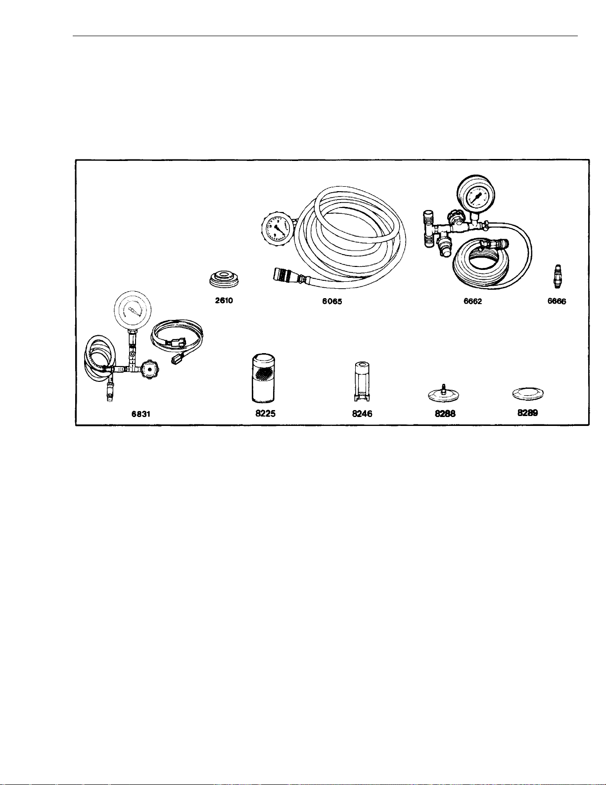
Special Tools ......................................................................................... 7
Special Equipment ................................................................................. 8
Design and Function ............................................................................. 9
Intakeand Exhaust System ..................................................................... 9
Preheater ............................................................................................... 9
D12C ................................................................................................. 9
Engines without Preheater ................................................................ 10
Engine Brake....................................................................................... 11
D12C ............................................................................................... 12
Crankcase Ventilation .......................................................................... 18
D12C ............................................................................................... 18
Exhaust Pressure Governor ................................................................ 19
D12C ............................................................................................... 21
EPG Control Valve............................................................................ 22
D12A ............................................................................................... 22
D12B ............................................................................................... 22
Air Restriction Indicator ....................................................................... 23
Turbocharger ........................................................................................ 24
D12A ............................................................................................... 24
Exhaust Manifold ................................................................................. 25
Tightening Sequence ........................................................................ 26
Troubleshooting ................................................................................... 27
Air Restriction Indicator,Checking ...................................................... 27
Service Procedures ............................................................................. 29
Air Filter Element, Replacement ......................................................... 29
IntakeManifold Gasket(s), Replacement ............................................ 30
Removal .......................................................................................... 31
Installation ....................................................................................... 31
Turbocharger,Replacement ................................................................ 32
Removal .......................................................................................... 32
Installation ....................................................................................... 33
Exhaust Manifold Gasket(s), Replacement ......................................... 34
(Turbocharger Removed) ................................................................... 34
Exhaust Pressure Governor,Replacement ......................................... 35
Exhaust Pressure Governor,Overhaul ............................................... 36
(Unit Removed) ................................................................................. 36
Disassembly .................................................................................... 36
Assembly ......................................................................................... 37
Charge Air Cooler Leak Test, Checking .............................................. 39
System Check...................................................................................... 41
Boost Pressure,Checking ................................................................... 41
Exhaust Backpressure,Checking ........................................................ 42
Pressure Testing Outlet Location ...................................................... 42
Backpressure Measuring Techniques ............................................... 42
Feedback
Operation Numbers1

2

Group 25 Intake and Exhaust System General
General
W2003244
D12C Engine
This information covers the Intake and Exhaust System for the D12, D12A, D12B, and
D12C engines.
3

4

Group 25 Intake and Exhaust System Specifications
Specifications
Intake and Exhaust System
Maximum Restriction (Rated speed full load) ............................................................................... 6.2 kPa (H20) (25 in.)
Air Cleaner torque
Plastic .......................................................................................................................................... 9 ± 2 Nm (7 ± 2 ft–lbs)
Metal ......................................................................................................................................... 20 ± 2 Nm (15 ± 2 ft-lbs)
For Specifications, including torques, refer to:
Service Manuals 200–890, Specifications, D12C
200–850, Specifiications, D12B
200–820, Specifications, D12A
IMPACT Function Group 25
Info Type: Specifications
5

Group 25 Intake and Exhaust System Specifications
6

Group 25 Intake and Exhaust System Tools
Tools
Special Tools
Servicing the VE D12 intake and exhaust systems requires the following special tools.
The tools are available from parts departments of Volvo Trucks North America, Inc.
When requesting tools, provide the appropriate number, preceded by ”999”, for exam-
ple, 9992610.
W0000406
9992610 Drift for overhauling exhaust pressure
governor
9996065 Gauge for checking boost pressure
9996666 Union for checking boost pressure
9996662 Pressure gauge
9996831 Vacuum gauge for checking pressure
drop indicator
9998225 Hollow drift for overhauling exhaust
pressure governor
9998246 Drift for overhauling exhaust pressure
governor
9998288 Connecting washer for leakage test of
charge air cooler
9998289 Sealing washer for leakage test of
charge air cooler
7

Group 25 Intake and Exhaust System Tools
Special Equipment
Like the special tools, the following are available from the parts department of Volvo
Trucks North America, Inc.. When requesting tools, provide the appropriate part num-
ber.
W0001840
1159794 Torque wrench 10–100 Nm (7–73 ft-lb)
W0001841
1159795 Torque wrench 40–340 Nm (30–250 ft-lb)
W0001842
1159796 Torque wrench 150–800 Nm (110–590 ft-lb)
8

Group 25 Intake and Exhaust System Design and Function
Design and Function
Intake and Exhaust System
Preheater
Selected versions of the D12 are equipped with a pre-
heater. Its purpose is to warm air in the intake manifold
when starting the engine. This heated air eases starting
at very low temperatures and reduces engine smoking
when starting a cold engine. The following conditions are
required to engage the preheater:
•The parking brake must be applied.
•The power take-off must not be engaged.
The preheater does not engage at coolant temperatures
over 10
C (50
F). At a coolant temperature of 10
C
(50
F), the preheating time is 25 seconds. At coolant
temperatures below –15
C(5
F), the preheating time is
55 seconds. Preheating time increases linearly between
10
C (50
F) and –15
C(5
F).
The post-heating time is always the same as the pre-
heating time.
T2006975
Fig. 1: Preheater
D12C
The D12C is equipped with a new preheater. The func-
tion of the starting heater is similar for both vehicle
variants, but the location of the relay differs. The pre-
heater on both engine variants is grounded to the engine
block through the intake manifold.
W2003281
Fig. 2: Preheater, D12C
9

Group 25 Intake and Exhaust System Design and Function
Engines without Preheater
On engines not equipped with a preheater, engine
coolant temperature determines the point at which fuel
injection begins while starting. The crankshaft rotates an
extra number of turns to increase cylinder temperature
before fuel injection begins. This gives more reliable
starting and reduces exhaust emissions during cold
starts down to about –15
C(5
F). This means that the
crankshaft may need to rotate about 3–4 rotations before
fuel injection begins and the engine fires.
An exhaust pressure governor is activated during start-
up.
10

Group 25 Intake and Exhaust System Design and Function
Engine Brake
W2003501
Fig. 3: D12 Engine
1 Camshaft
2 Shutter
3 Exhaust pressure governor
4 Rocker arm
5 Control valve
6 Shim
The Volvo Engine Brake (VEB) is a combination of two
brake systems: the exhaust brake and the compression
brake.
Exhaust brake
The exhaust pressure governor uses a shutter mounted
in the exhaust outlet from the turbocharger. This shutter,
connected to the exhaust pressure governor plunger,
can restrict the exhaust gas flow. This creates a braking
effect during the exhaust stroke when the exhaust gases
cannot evacuate freely and create an overpressure be-
tween the pistons and the shutter.
Compression brake
During the engine compression stroke and combustion
(operating) stroke, the controlled opening of the exhaust
valves creates an overpressure in the combustion cham-
ber. This, in turn, produces a braking effect on the
crankshaft.
The camshaft on an engine with a compression brake
has two extra lobes on each exhaust cam profile. The
lifting height of the extra lobes is very low when com-
pared to the normal exhaust lobes. To enable the extra
lobes to open the exhaust valves, the exhaust rocker
arms are arranged in a manner by which the valve clear-
ance can be reduced during the braking sequence.
ShimShims are available in thickness invtervals of 0.05
mm (0.0002 in). Sizes range from 2.0–2.4 mm (0.08–
0.094 in) and from 3.2–3.95 mm(0.126–0.156 in).
Thickness is stamped on the shims.
11

Group 25 Intake and Exhaust System Design and Function
D12C
The VEB solenoid has been moved to the center of the
rocker shaft. The oil supply is internal, rather than having
the external piping visible.
Control Valve
The control valve is mounted on the cylinder head under
the valve cover, and is connected to the oil system
ahead of the rocker arm shaft. Its purpose is to reduce
the oil pressure to the rocker arms while the engine is
operating (compression brake not activated).
There is always full system oil pressure to the control
valve intake (1) because the intake is connected via a
pipe to the lube oil gallery in the cylinder block. The oil
pressure to the rocker arm shaft can be increased via a
solenoid valve (2) mounted on the control valve, from ap-
proximately 100 kPa (14.5 psi) while the engine is
operating, to more than 200 kPa (29 psi) during com-
pression braking.
While the engine is operating, the oil pressure is reduced
after the control valve by the plunger (3) being held in
balance by the force of a spring (4) and the oil pressure
in the oil chamber (6) on the opposite side of the plunger.
When the solenoid valve is activated, the oil chamber (6)
is drained and the spring (4) presses the plunger (3) to
its end position. The plunger completely opens the oil
outlet (5) to increase oil pressure to the rocker arm shaft. T2006835
Fig. 4: Control Valve
1 Oil inlet
2 Solenoid valve
3 Plunger
4 Spring
5 Oil outlet
6 Oil chamber
12

Group 25 Intake and Exhaust System Design and Function
Camshaft on Engine with Compression Brake
The camshaft on an engine with a compression brake
has an induction lobe (1) and a decompression lobe (2)
—in addition to the normal exhaust lobe (3) —on each
cam profile for the exhaust valves.
The induction and decompression lobe lifting height is
0.8 mm (0.032 in.) above the basic circle, which is equiv-
alent to approximately 1.1 mm (0.043 in.) at the valve
bridge.
The induction lobe is positioned so that it opens the ex-
haust valves at the end of the intake stroke and holds
them open until the beginning of the compression stroke.
The decompression lobe is positioned so that it opens
the exhaust valves at the end of the compression stroke.
In order for the induction and decompression lobes to
open the exhaust valves, the valve clearance must be re-
duced to zero by the activation of the non-return valve
and plunger located in the rocker arm for the exhaust
valves.
T2006826
Fig. 5: Cam Shaft Profile
1 Induction lobe
2 Decompression lobe
3 Exhaust lobe
13

Group 25 Intake and Exhaust System Design and Function
Exhaust Rocker Arms
The exhaust rocker arms on an engine with a compres-
sion brake are larger than those on a conventional
engine.
The rocker arm includes a non-return valve (2) and a
plunger (3) with a pressure limiting valve, the purpose of
which is to regulate the oil flow during compression brak-
ing.
The rocker arm is held in its position against the valve
bridge with the help of a spring tab (1).
The valve clearance is greater than that on an engine
without a compression brake, because the induction and
decompression lobes must not open the exhaust valves
while the engine is in normal operating mode (compres-
sion brake not activated).
Valve adjustment is carried out with shims which are
placed on the valve bridge.
Note: A maximum of two shims are allowed to obtain
proper valve clearance.
W2003502
Fig. 6: Rocker arm assembly, side view:
1 Spring tab
2 Non-return valve
3 Rocker arm plunger
4 Shims
Non-Return Valve
The engine brake has a non-return valve, consisting of a
plunger (1), spring (2) and a ball (3) in the rocker arm.
When oil from the rocker arm shaft enters the valve, the
movement of the plunger is determined by the spring
force and the oil pressure.
When the oil pressure is low —approximately 100 kPa
(14.5 psi); the control valve is in its normal engine oper-
ating position —the plunger (1) will not move out of its
rest position because the oil pressure is not sufficient to
overcome the spring force. The plunger pin prevents the
ball (3) from entering the seating area, and the oil can
then flow freely through the valve in both directions.
When the control valve takes up the position for com-
pression braking, the oil pressure increases to the
non-return valve. The spring force in the non-return valve
is such that when the oil pressure exceeds approxi-
mately 200 kPa (29 psi), the spring force is overcome
and the plunger (1) moves so that it no longer influences
the ball (3). The spring (5) presses the ball (3) against
the seat and prevents the oil contained above the
plunger (4) from flowing past the ball (3). This forms high
oil pressure above the plunger (4).
T2006834
Fig. 7: Rocker arm assembly, top view:
1 Plunger
2 Spring
3 Ball
4 Rocker arm plunger
5 Spring
14

Group 25 Intake and Exhaust System Design and Function
Rocker Arm Plunger
The purpose of the rocker arm plunger is to eliminate all
valve clearance during the compression braking.
Engine Operation
When the engine is operating (compression brake not
activated), there is reduced oil pressure —approx. 100
kPa (14.5 psi) —via the control valve to the rocker arm
shaft and the rocker arm non-return valve (1) is open. Oil
can flow freely through the non-return valve in both di-
rections. As a result, no oil pressure is built up between
the rocker arm plunger (2) and the rocker arm.
The set valve clearance is great enough to prevent the
camshaft induction and decompression lobes from open-
ing the exhaust valves.
The valve mechanism operates the same as on an en-
gine without a compression brake; in other words, only
the exhaust lobe opens the exhaust valves.
T2006828
Fig. 8: Rocker Arm Plunger
1 Non-return valve
2 Rocker arm plunger
Compression Braking
During compression braking, the control valve does not
reduce the oil pressure, so an oil pressure of at least
200 kPa (29 psi) is delivered to the rocker arm shaft.
The pressure in the rocker arm non-return valve (1) be-
comes so great that the plunger in the non-return valve
is moved out of its rest position, and the ball now func-
tions as a non-return valve. Pressure is built up between
the rocker arm plunger (2) and the rocker arm. The
plunger is pressed out and presses the rocker arm roller
against the lobes on the camshaft. In this way, the valve
clearance is eliminated and the lifting height on the in-
duction and decompression lobes is sufficient to open
the exhaust valves.
The rocker arm plunger is fitted with a pressure limiting
valve (3). When the oil pressure between the rocker arm
plunger and the rocker arm becomes too great, the pres-
sure limiting valve opens and oil can exit through the
hole in the bottom of the plunger. The opening pressure
of the pressure limiting valve is governed by the force of
the valve spring.
T2006836
Fig. 9: Rocker Arm Plunger
1 Non-return valve
2 Rocker arm plunger
3 Pressure limiting valve
15

Group 25 Intake and Exhaust System Design and Function
Control System
The engine brake is connected to the throttle pedal and
is activated when the pedal is completely released, ac-
cording to the selection made with the engine brake
switch on the instrument panel.
The selection made with this switch also regulates en-
gine braking activated by the cruise control.
Note: The engine brake functions as long as the engine
control system has received signals from engine sensors
indicating that the required preconditions for engine
braking have been met. For example, the engine speed
must be greater than 1100 rpm, the vehicle speed must
be greater than 12 km/h (7.5 mph), and the engine tem-
perature must be above 70
C (160
F).
The switch has three positions:
0No engine brake engaged
1Exhaust brake, EPG
2Exhaust brake and compression brake, VEB
T2006953
Fig. 10: Switch for engine brake
Exhaust Brake
When exhaust braking, the exhaust pressure governor
(EPG) is activated with a control pressure of approxi-
mately 750 kPa (110 psi). At this point, the shutter is
forced out of the EPG and into the shutter housing. This
restricts the flow of exhaust gases out of the cylinders,
as the shutter blocks the outlet from the turbocharger.
Restricting the flow of exhaust gases forms an air cush-
ion between the shutter and the piston crowns. During
the exhaust stroke, this air cushion provides a braking
effect on the pistons as the exhaust valves are then
opened.
The higher the engine speed during the exhaust braking,
the greater the braking effect.
T2006832
Fig. 11: Exhaust pressure governor
16

Group 25 Intake and Exhaust System Design and Function
Compression Brake
The exhaust brake is always engaged in conjunction
with the compression brake. In the compression brake
induction phase, the exhaust brake creates an overpres-
sure in the exhaust manifold, making the compression
brake more efficient.
Induction phase
The induction phase begins at the end of the intake
stroke and continues slightly into the compression stroke.
The piston travels towards its bottom dead center posi-
tion and the camshaft induction lobe opens the exhaust
valves for the time required to fill the cylinder with the
overpressure created by the exhaust brake in the ex-
haust manifold.
When the induction lobe closes the exhaust valves, the
cylinder has an overpressure at the start of the compres-
sion stroke.
This overpressure considerably increases the compres-
sion during the compression stroke, which in turn
creates a powerful braking effect during the upward
movement of the piston.
T2006830
Fig. 12: Charging phase
Decompression phase
At the end of the compression stroke, when the piston is
nearing its top dead center position, the camshaft
decompression lobe opens the exhaust valves and re-
leases the pressure out of the cylinder.
Shortly before the bottom dead center position, the ex-
haust valves are opened by the ordinary exhaust lobe.
During the exhaust stroke, the counterpressure is cre-
ated in the exhaust manifold which, in turn, has a
braking effect because the exhaust pressure governor
shutter is still restricting the flow of exhaust gases out of
the turbocharger.
T2006831
Fig. 13: Decompression phase
17

Group 25 Intake and Exhaust System Design and Function
Crankcase Ventilation
D12C
The D12C has new crankcase ventilation with its outlet
from the upper timing gear cover.
The timing gear cover is designed with an oil trap to pre-
vent oil from escaping through the ventilation tube.
T2012791
Fig. 14: Crankcase Ventilation, D12C
W2003503
Fig. 15: Crankcase Ventilation, D12B and D12C
W2003504
Fig. 16: Crankcase Ventilation, D12A
18
This manual suits for next models
3
Table of contents
Other Volvo Truck manuals

Volvo
Volvo FM Series Quick start guide

Volvo
Volvo L90E User manual

Volvo
Volvo VN 2002 User manual

Volvo
Volvo FM User manual

Volvo
Volvo A35E FS User manual

Volvo
Volvo VN User manual

Volvo
Volvo FM 2 Series User manual

Volvo
Volvo FH User manual

Volvo
Volvo FH12 LHD Quick start guide

Volvo
Volvo VN 2002 User manual