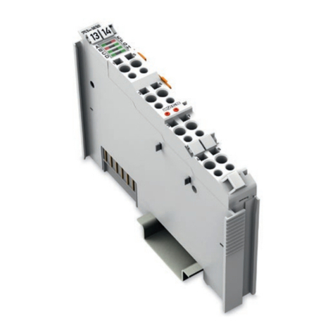
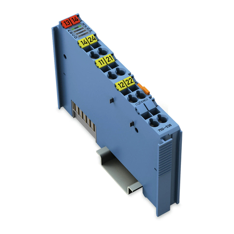
WAGO 750-515 User manual

Pos:2/Dokumentationallgemein/Einband/EinbandHandbuch- F ro nts ei t e 2015 - mit DocV ari abl e n (Sta nd ar d)@ 9\mod_1285229289866_0.docx@ 64941 @ @ 1
WAGO-I/O-SYSTEM 750
Manual
750-515
4DO 250V AC 2.0A/ Relais 4NO/ Potential Free
4-
Channel Relay Output Module 250 VAC, 2.0 A;
Potential Free; 4 Make Contacts
Version 1.0.1
Pos: 3 / All e Seri e n ( Al lg e m ein e M od ul e) /R ec htl ic h es , A ll ge mei n es /I mpr e ss um für Sta nd ard h an d büc h er - al lg . A ng a be n, Ansc hri ft en, T elef o nn u m mer n und E -Mai l-Adr es s e n @ 3\mod_1219151118203_21.docx@ 21060@ @ 1

2 WAGO-I/O-SYSTEM 750
750-515 4DO 250V AC 2.0A/ Relais 4NO/ Potential Free
Manual
Version 1.0.1
© 2016 by WAGO Kontakttechnik GmbH & Co. KG
All rights reserved.
WAGO Kontakttechnik GmbH & Co. KG
Hansastraße 27
D-32423 Minden
Phone: +49 (0) 571/8 87 – 0
Fax: +49 (0) 571/8 87 – 1 69
E-Mail: [email protected]om
Web: http://www.wago.com
Technical Support
Phone: +49 (0) 571/8 87 – 5 55
Fax: +49 (0) 571/8 87 – 85 55
E-Mail: [email protected]om
Every conceivable measure has been taken to ensure the accuracy and
completeness of this documentation. However, as errors can never be fully
excluded, we always appreciate any information or suggestions for improving the
documentation.
E-Mail: documentation@wago.com
We wish to point out that the software and hardware terms as well as the
trademarks of companies used and/or mentioned in the present manual are
generally protected by trademark or patent.
=== Ende d er Lis t e f ür Te xt mar ke Ei nb and _ vor n e = = =

WAGO-I/O-SYSTEM 750 Table of Contents 3
750-515 4DO 250V AC 2.0A/ Relais 4NO/ Potential Free
Manual
Version 1.0.1
Pos: 5 /D o ku ment ati on allg e mei n /Ver zei c hni ss e/I nh alt s verz ei ch nis - Üb erschri ft oG und V erzeic hnis @ 3\mod_1219151230875_21.docx@ 21063 @ @ 1
Table of Contents
1Notes about this Documentation................................................................. 5
1.1 Validity of this Documentation................................................................. 5
1.2 Copyright................................................................................................... 5
1.3 Symbols..................................................................................................... 6
1.4 Number Notation....................................................................................... 8
1.5 Font Conventions ...................................................................................... 8
2Important Notes ........................................................................................... 9
2.1 Legal Bases ............................................................................................... 9
2.1.1 Subject to Changes ............................................................................... 9
2.1.2 Personnel Qualifications....................................................................... 9
2.1.3 Use of the WAGO-I/O-SYSTEM 750 in Compliance with
Underlying Provisions.......................................................................... 9
2.1.4 Technical Condition of Specified Devices......................................... 10
2.2 Safety Advice (Precautions).................................................................... 11
3Device Description ..................................................................................... 13
3.1 View ........................................................................................................ 15
3.2 Connectors............................................................................................... 16
3.2.1 Data Contacts/Internal Bus................................................................. 16
3.2.2 Power Jumper Contacts/Field Supply ................................................ 16
3.2.3 CAGE CLAMP®Connectors ............................................................. 17
3.3 Display Elements .................................................................................... 18
3.4 Schematic Diagram ................................................................................. 19
3.5 Technical Data ........................................................................................ 20
3.5.1 Device................................................................................................. 20
3.5.2 Power Supply...................................................................................... 20
3.5.3 Communication .................................................................................. 20
3.5.4 Outputs ............................................................................................... 21
3.5.5 Connection Type ................................................................................ 21
3.5.6 Climatic Environmental Conditions................................................... 21
3.5.7 Load Limiting Curve .......................................................................... 22
3.5.8 Life Cycle Curve ................................................................................ 23
3.6 Approvals ................................................................................................ 24
3.7 Standards and Guidelines........................................................................ 26
4Process Image ............................................................................................. 27
5Mounting..................................................................................................... 28
5.1 Mounting Sequence................................................................................. 28
5.2 Inserting and Removing Devices ............................................................ 29
5.2.1 Inserting the I/O Module .................................................................... 29
5.2.2 Removing the I/O Module.................................................................. 30
6Connect Devices ......................................................................................... 31
6.1 Connecting a Conductor to the CAGE CLAMP®................................... 31
6.2 Connection Examples.............................................................................. 33
6.3 Protection Class II and III Actuators....................................................... 33
6.4 Protection Class I Actuators.................................................................... 33

4 Table of Contents WAGO-I/O-SYSTEM 750
750-515 4DO 250V AC 2.0A/ Relais 4NO/ Potential Free
Manual
Version 1.0.1
6.5 Protective Circuits for Contacts of Relay Modules................................. 34
7Use in Hazardous Environments .............................................................. 36
7.1 Marking Configuration Examples........................................................... 37
7.1.1 Marking for Europe According to ATEX and IEC-Ex ...................... 37
7.1.2 Marking for America According to NEC 500.................................... 42
7.2 Installation Regulations........................................................................... 43
7.2.1 Special Conditions for Safe Use
(TÜV 14 ATEX 148929 X)................................................................ 44
7.2.2 Special Conditions for Safe Use
(ATEX Certificate TÜV 12 ATEX 106032 X) ................................. 45
7.2.3 Special Conditions for Safe Use
(IEC-Ex Certificate TUN 14.0035X) ................................................. 46
7.2.4 Special Conditions for Safe Use
(IEC-Ex Certificate IECEx TUN 12.0039 X) .................................... 47
7.2.5 Special Conditions for Safe Use according to ANSI/ISA 12.12.01... 48
List of Figures ...................................................................................................... 49
List of Tables........................................................................................................ 50
=== En de der Lis te für T extmar ke Verz eich nis_vor ne == =

WAGO-I/O-SYSTEM 750 Notes about this Documentation 5
750-515 4DO 250V AC 2.0A/ Relais 4NO/ Potential Free
Manual
Version 1.0.1
Pos: 7 / All e Seri e n ( Al lg e m ein e M od ul e) /Ü b ers c hri ft en/ N e ue Ü b ers c hri ft en /E be n e 1H in w eis e z u dies er Do kum e nt ati on - Ü b ers chr if t 1 @ 4\mod_1237987661750_21.docx@ 29029 @ 1@ 1
1 Notes about this Documentation
Pos: 8 /Al le S eri en ( Allg em ein e Mod ul e)/Si cher h eits- unds onstige Hinweise/HinweisHinweis:Dokumentationaufbewahren @ 4\mod_1237987339812_21.docx@ 29026@ @ 1
Always retain this documentation!
This documentation is part of the product. Therefore, retain the documentation
during the entire service life of the product. Pass on the documentation to any
subsequent user. In addition, ensure that any supplement to this documentation is
included, if necessary.
Pos: 9 / All e Seri e n ( Al lg e m ein e M od ul e) /Ü b ers c hri ft en/ N e ue Ü b ers c hri ft en /E be n e 2G ül ti g keit s ber ei c h - Ü b ers chr if t 2 @ 12\mod_1338912448776_21.docx@ 964 69 @ 2 @ 1
1.1 Validity of this Documentation
Pos: 10 /S er ie 75 0 ( WA GO -I/O-S YST E M) /Hi n weis e z ur Do kum e ntat i on/ Gül tig kei ts b erei c h/G ülti g k eits ber ei ch Dok um en tat io n Bus kl e mme 75 0-xxx x,o hne V ariant enang abe @ 14 \mod_1358944037947_21.docx@109346@ @ 1
This documentation is only applicable to the I/O module 750-515
(4DO 250V AC 2.0A/ Relais 4NO/ Potential Free).
Pos: 11 /S er ie 75 0 ( WA GO -I/O-S YST EM )/H i nwei se z ur D o kum ent ati on/H i nw eise /Ac ht ung : H in wei s z ur D o ku ment ati on Bus kl emme n 750-xxxx @ 4\ mod_1237986979656_21.docx@ 29023@ @ 1
The I/O module 750-515 shall only be installed and operated according to the
instructions in this manual and in the manual for the used fieldbus
coupler/controller.
Consider power layout of the WAGO-I/O-SYSTEM 750!
In addition to these operating instructions, you will also need the manual for the
used fieldbus coupler/controller, which can be downloaded at www.wago.com.
There, you can obtain important information including information on electrical
isolation, system power and supply specifications.
Pos: 12.1 /All e Seri en ( Al lg emei ne M o dul e)/Ü ber sc hri fte n/ Ebe ne 2/Ur h eber sc hutz - Über sc hr ift 2 @ 23\mod_1435647042188_21.docx @ 184808@ 2@ 1
1.2 Copyright
Pos: 12.2 / All e Seri en ( Al lg e mei ne M od ul e)/R ec ht lic hes , A llg e mei nes /U rh eb ersc hu tz aus f ührl ich @ 4\mod_1235565145234_21.docx @ 27691@ @1
This Manual, including all figures and illustrations, is copyright-protected. Any
further use of this Manual by third parties that violate pertinent copyright
provisions is prohibited. Reproduction, translation, electronic and phototechnical
filing/archiving (e.g., photocopying) as well as any amendments require the
written consent of WAGO Kontakttechnik GmbH & Co. KG, Minden, Germany.
Non-observance will involve the right to assert damage claims.
Pos:12.3/Dokumentationallgemein/Gliederungselemente/---Seite nwe chs el--- @ 3\mod_1221108045078_0.docx @ 21810@ @ 1

6 Notes about this Documentation WAGO-I/O-SYSTEM 750
750-515 4DO 250V AC 2.0A/ Relais 4NO/ Potential Free
Manual
Version 1.0.1
Pos: 12.4 /All e Seri en ( Al lg emei ne M o dul e)/Ü ber sc hri fte n/N eu e Ü b ersc hrif te n/ Ebe ne 2 S ymbol e - Ü ber sc hr ift 2 @ 13\mod_1351068042408_21.docx@ 105270 @ 2@ 1
1.3 Symbols
Pos: 12 .5.1 /Al le Seri en (All gemei ne Mod ule)/ Sicher heits- u nd sons tig e H i n weis e/ Ge fa hr /G ef a hr : _ War nu ng vor P er s on ens ch ä de n al lg e mei n _ - Er läu ter ung @ 13 \mod_1343309450020_21.docx@ 101029@ @ 1
Personal Injury!
Indicates a high-risk, imminently hazardous situation which, if not avoided, will
result in death or serious injury.
Pos: 12 .5.2 /Al le Seri en (All gemei ne Mod ule)/ Sicher heits- u nd sons ti g e Hi n weis e/ Ge fahr /G ef a hr: _War nu ng vor P er s onen sc hä de n d urc h el e ktri sc he n S tro m_ - Erläuterung@ 13\mod_1343309694914_21.docx@ 101030@ @ 1
Personal Injury Caused by Electric Current!
Indicates a high-risk, imminently hazardous situation which, if not avoided, will
result in death or serious injury.
Pos: 12 .5.3 /Al le Seri en (All gemei ne Mod ule)/ Sicher heits- u nd sons tig e H i n weis e/ W ar nung / W ar nung : _W ar nung vor P ersone nsch äden all gemei n_ - Erläuterung@ 13\mod_1343309877041_21.docx@ 101035@ @ 1
Personal Injury!
Indicates a moderate-risk, potentially hazardous situation which, if not avoided,
could result in death or serious injury.
Pos: 12 .5.4 /Al le Seri en (All gemei ne Mod ule)/ Sicher heits- u nd sons ti g e Hi n weis e/ Vors ic ht /V ors ic ht: _War n ung vor Per s one nsc hä d en al lg em ein _ - Erläuterung@ 13\mod_1343310028762_21.docx@ 101038@ @ 1
Personal Injury!
Indicates a low-risk, potentially hazardous situation which, if not avoided, may
result in minor or moderate injury.
Pos: 12 .5.5 /Al le Seri en (All gemei ne Mod ule)/ Sicher heits- u nd sons ti g e Hi n weis e/ Ac htu ng/ Ac htu ng : _War nu ng vor Sachs c häd en allg e mei n_ - Erläuterung@ 13\mod_1343310134623_21.docx@ 101041@ @ 1
Damage to Property!
Indicates a potentially hazardous situation which, if not avoided, may result in
damage to property.
Pos: 12.5 .6 /All e Ser ie n ( Al lg emei ne Mod ule) / Sich erh eit s- und so ns tig e H i n weis e/ Ac htu ng/ Ach tu ng : _ War nu ng vor Sac hsc h äden dur c h el ek tros t atis ch e Aufl adu ng _ - Er l äut er ung @ 13\mod_1343310227702_21.docx@ 101044@ @ 1
Damage to Property Caused by Electrostatic Discharge (ESD)!
Indicates a potentially hazardous situation which, if not avoided, may result in
damage to property.
Pos: 12 .5.7 /Al le Seri en (All gemei ne Mod ule)/ Sicher heits- u nd sonstige Hi nweise/Hinweis/Hinweis:_Wichtiger Hin weis allgemein_- Erläuterung @ 13\mod_1343310326906_21.docx@ 101047@ @ 1
Important Note!
Indicates a potential malfunction which, if not avoided, however, will not result in
damage to property.
Pos: 12 .5.8 /Al le Seri en (All gemei ne Mod ule)/ Sicher heits- u nd sons tig e H i n weis e/I nf or ma tio n/I nf or ma tio n: _W ei ter e I nf or ma ti o n al lg e mei n_ - Erl äu ter ung @ 13 \mod_1343310439814_21.docx@ 101051@ @ 1

WAGO-I/O-SYSTEM 750 Notes about this Documentation 7
750-515 4DO 250V AC 2.0A/ Relais 4NO/ Potential Free
Manual
Version 1.0.1
Additional Information:
Refers to additional information which is not an integral part of this
documentation (e.g., the Internet).
Pos: 12.6/Dokumentationallgemein/Gliederungselemente/---Seiten we chs el --- @ 3\mod_1221108045078_0.docx@ 21810 @ @ 1

8 Notes about this Documentation WAGO-I/O-SYSTEM 750
750-515 4DO 250V AC 2.0A/ Relais 4NO/ Potential Free
Manual
Version 1.0.1
Pos: 12.7 /All e Seri en ( Al lg emei ne M o dul e)/Ü ber sc hri fte n/ Ebe ne 2/Dar st ell ung der Z a hle ns yst em e - Ü bers c hri ft 2 @ 23\mod_1435647128078_21.docx @ 18481 1 @ 2@ 1
1.4 Number Notation
Pos: 12.8 /All e Seri en ( Al lg emei ne Mo d ule) /R ec htli ch es , A llg e mei nes /Z ahl ens y st e me @ 3\mod_1221059454015_21.docx@ 21711@ @ 1
Table 1: Number Notation
Number Code
Example
Note
Decimal
100
Normal notation
Hexadecimal
0x64
C notation
Binary
'100'
'0110.0100'
In quotation marks, nibble separated with
dots (.)
Pos: 12.9 /All e Seri en ( Al lg emei ne M o dul e)/Ü ber sc hri fte n/ Ebe ne 2/Sc hri ft ko nvent i one n - Ü ber sc hri ft 2 @ 23\mod_1435647186005_21.docx@ 184 814 @ 2 @ 1
1.5 Font Conventions
Pos: 12.1 0 / All e Seri e n ( Al lg e m ein e M o dul e) /R e ch tl ich es , A ll ge m ein es / Sc hr ift k onv e nti on en @ 3 \mod_1221059521437_21.docx@ 21714@ @1
Table 2: Font Conventions
Font Type
Indicates
italic
Names of paths and data files are marked in italic-type.
e.g.: C:\Program Files\WAGO Software
Menu
Menu items are marked in bold letters.
e.g.: Save
>
A greater-than sign between two names means the selection of a
menu item from a menu.
e.g.: File > New
Input
Designation of input or optional fields are marked in bold letters,
e.g.: Start of measurement range
“Value”
Input or selective values are marked in inverted commas.
e.g.: Enter the value “4 mA” under Start of measurement range.
[Button]
Pushbuttons in dialog boxes are marked with bold letters in square
brackets.
e.g.: [Input]
[Key]
Keys are marked with bold letters in square brackets.
e.g.: [F5]
Pos: 13 /D o ku me nt ati o n al lg e mei n/ Gl ie der ung s ele m e nte /---Seit e n we chs el --- @ 3\mod_1221108045078 _0.doc x@ 2 1810 @ @1

WAGO-I/O-SYSTEM 750 Important Notes 9
750-515 4DO 250V AC 2.0A/ Relais 4NO/ Potential Free
Manual
Version 1.0.1
Pos: 14 /A ll e Ser i en ( All ge mei ne M od ule) /Ü b ersc hrif te n/N eu e Ü ber schr if te n/E be ne 1 Wic hti ge Erlä ut eru nge n - Ü b er schr i f t 1 @ 4\mod_1241428899156_21.docx@ 32170 @ 1@ 1
2 Important Notes
Pos: 15.1 /All e Seri en ( Al lg emei ne Mo d ule) /R ec htli ch es , A llg e mei nes Wic ht ig e Er lä ut eru ng en - Ei nl ei t ung @ 3\mod_1221059818031_21.docx@ 21717@ @ 1
This section includes an overall summary of the most important safety
requirements and notes that are mentioned in each individual section. To protect
your health and prevent damage to devices as well, it is imperative to read and
carefully follow the safety guidelines.
Pos: 15.2 /All e Seri en ( Al lg emei ne M o dul e)/Ü ber sc hri fte n/N eu e Ü b ersc hrif te n/ Ebe ne 2R ec htl ic he Gru ndl age n - Ü b ers chr if t 2 @ 3\mod_1221060626343_21.docx@ 21726 @ 2@ 1
2.1 Legal Bases
Pos: 15.3 /All e Seri en ( Al lg emei ne Mo d ule) /R ec htli ch es , A llg e mei nes Ä nder u ngs vor be h alt - Ü b er sc hri f t 3 un d I n halt @ 3 \mod_1221060036484_21.docx @ 21720@ 3@ 1
2.1.1 Subject to Changes
WAGO Kontakttechnik GmbH & Co. KG reserves the right to provide for any
alterations or modifications that serve to increase the efficiency of technical
progress. WAGO Kontakttechnik GmbH & Co. KG owns all rights arising from
the granting of patents or from the legal protection of utility patents. Third-party
products are always mentioned without any reference to patent rights. Thus, the
existence of such rights cannot be excluded.
Pos:15.4/Serie750(WAGO-I/O-S YST EM )/ Wi c hti g e Er lä ut er u ng en/ Per s on al q ual if i kat io nP ers on alq u ali fi kation 750-xxxx- Ü bersc hrift 3 u nd Inh alt @ 3\mod_1224061208046_21.docx@ 24063@ 3 @ 1
2.1.2 Personnel Qualifications
All sequences implemented on WAGO-I/O-SYSTEM 750 devices may only be
carried out by electrical specialists with sufficient knowledge in automation. The
specialists must be familiar with the current norms and guidelines for the devices
and automated environments.
All changes to the coupler or controller should always be carried out by qualified
personnel with sufficient skills in PLC programming.
Pos:15.5/Serie750(WAGO-I/O-SYSTEM)/WichtigeErläuterungen/BestimmungsgemäßeVerwendungBestimmungsgemäßeVerwendung750-xxxx- Ü b ers chr if t 3 un d I n hal t @ 3\mod_1224064151234_21.docx@ 24070 @3 @ 1
2.1.3 Use of the WAGO-I/O-SYSTEM 750 in Compliance with
Underlying Provisions
Fieldbus couplers, fieldbus controllers and I/O modules found in the modular
WAGO-I/O-SYSTEM 750 receive digital and analog signals from sensors and
transmit them to actuators or higher-level control systems. Using programmable
controllers, the signals can also be (pre-) processed.
The devices have been developed for use in an environment that meets the IP20
protection class criteria. Protection against finger injury and solid impurities up to
12.5 mm diameter is assured; protection against water damage is not ensured.
Unless otherwise specified, operation of the devices in wet and dusty
environments is prohibited.
Operating the WAGO-I/O-SYSTEM 750 devices in home applications without
further measures is only permitted if they meet the emission limits (emissions of
interference) according to EN 61000-6-3. You will find the relevant information
in the section “Device Description” > “Standards and Guidelines” in the manual
for the used fieldbus coupler/controller.

10 Important Notes WAGO-I/O-SYSTEM 750
750-515 4DO 250V AC 2.0A/ Relais 4NO/ Potential Free
Manual
Version 1.0.1
Appropriate housing (per 2014/34/EU) is required when operating the WAGO-
I/O-SYSTEM 750 in hazardous environments. Please note that a prototype test
certificate must be obtained that confirms the correct installation of the system in
a housing or switch cabinet.
Pos: 15.6 /All e Seri en ( Al lg emei ne Mo d ule) /R ec htli ch es , A llg e mei nesT ec hni s ch er Z us tan d der G er ät e - Ü bersc hrift 3 u nd Inhal t @ 3\mod_1221060446109_21.docx@ 21723@ 3 @ 1
2.1.4 Technical Condition of Specified Devices
The devices to be supplied ex works are equipped with hardware and software
configurations, which meet the individual application requirements. WAGO
Kontakttechnik GmbH & Co. KG will be exempted from any liability in case of
changes in hardware or software as well as to non-compliant usage of devices.
Please send your request for modified and new hardware or software
configurations directly to WAGO Kontakttechnik GmbH & Co. KG.
Pos:15.7/Dokumentationall ge mei n/ G li e der ung s el em en te /---Sei t en we chs el --- @ 3\mod_1221108045078_0.docx@ 21810 @ @ 1

WAGO-I/O-SYSTEM 750 Important Notes 11
750-515 4DO 250V AC 2.0A/ Relais 4NO/ Potential Free
Manual
Version 1.0.1
Pos: 15.8 /All e Seri en ( Al lg emei ne M o dul e)/Ü ber sc hri fte n/N eu e Ü b ersc hrif te n/ Ebe ne 2 Sic her hei ts hi nwei se - Ü b ers chr if t 2 @ 6\mod_1260180299987_21.docx@ 46724 @ 2@ 1
2.2 Safety Advice (Precautions)
Pos: 15.9 /All e Seri en ( Al lg emei ne D ok um ent e) ( Al lg emei ne Mo dul e)/ Wic htig e Erlä ut eru nge n/ Sich erh eits hi n weis e/ Einl ei tung Si cher h eits hi nw eis e H ar d war e @ 6\mod_1260180170493_21.docx@ 46720@ @ 1
For installing and operating purposes of the relevant device to your system the
following safety precautions shall be observed:
Pos: 15.1 0. 1 / All e Seri e n ( Al lg e m ein e D o ku me nt e) ( Al lg e mei n e M o dul e) / Wic ht ig e Erlä uter u ngen /S ic h er h eits hi n wei se /G ef ahr /G ef ahr : Nich t an G er ät en unter Sp a nnu ng ar beit e n! @ 6\mod_1260180365327_21.docx @ 46727 @ @ 1
Do not work on devices while energized!
All power sources to the device shall be switched off prior to performing any
installation, repair or maintenance work.
Pos: 15.1 0. 2 / S eri e 750 ( W AG O-I/O-SY STEM )/Wic htig e Er l äuter ung en /Sic her hei ts - und s o nsti g e H i n w eise /G ef ahr / Ge fa hr : Einb au 07 50-xxx x nur i n Geh äus en, Sc hrä n ken oder el ektr isc he n Betr ie bsr äu me n! @ 6\mod_1260180556692_21.docx@ 46731@ @ 1
Install the device only in appropriate housings, cabinets or in electrical
operation rooms!
The WAGO-I/O-SYSTEM 750 and its components are an open system. As such,
install the system and its components exclusively in appropriate housings,
cabinets or in electrical operation rooms. Allow access to such equipment and
fixtures to authorized, qualified staff only by means of specific keys or tools.
Pos: 15.1 0. 3 / All e Seri e n ( Al lg e m ein e D o ku me nt e) ( Al lg e mei n e M o dul e) / Wic ht ig e Erlä uter u ngen /S ic h er h eits hi n wei se /G ef ahr /G ef ahr : Unfal l v erh üt ung s v ors c hri ft en bea ch te n! @ 6\mod_1260180657000_21.docx @ 46735@ @ 1
Pos: 15.1 0. 4 / All e Seri e n ( Al lg e m ein e D o ku me nt e) ( Al lg e mei n e M o dul e) / Wic ht ig e Erlä uter u ngen /S ic h er h eits hi n wei se /G ef ahr /G ef ahr : Auf normg er ec ht e n A ns c hlu ss ac ht en! @ 6 \mod_1260180753479_21.docx@ 46739@ @1
Pos: 15.1 1 /Al le Seri en ( Allg em ein e M odul e)/Si ch erh eits - und s o nsti ge Hin w eis e/G ef a hr/ G ef ahr: Lei t ung en nur in s pa n nu ngs fr ei e m Z ust a nd ansc hl ies s e n od er tr enn en @ 1 6\mod_1372153982130_21.docx@ 124277@ @ 1
Only connect or disconnect lines when power is safely isolated!
The lines to the device can carry hazardous voltages and currents. Contact with
the lines when live can result in severe injury or death. Therefore, read and
observe the following safety rules before you perform work on the device:
1. Disconnect the respective system component from the power supply.
2. Secure the system component against unintentional restart.
3. Check if the voltage is positively isolated.
Pos: 15.1 2. 1 / All e Seri e n ( Al lg e m ein e D o ku me nt e) ( Al lg e mei n e M o dul e) / Wic ht ig e Erlä uter u ngen /S ic h er h eits hi nw eis e/ Ac htu ng /Ac ht u ng: D ef ek te oder besc h ädig t e G er ät e aus ta usc h en! @ 6 \mod_1260180857358_21.docx@ 46743 @ @ 1
Replace defective or damaged devices!
Replace defective or damaged device/module (e.g., in the event of deformed
contacts), since the long-term functionality of device/module involved can no
longer be ensured.
Pos: 15.1 2. 2 / All e Seri e n ( Al lg e m ein e D o ku me nt e) ( Al lg e mei n e M o dul e) / Wic ht ig e Erlä uter u ngen /S ic h er h eits hi n wei se /Ac ht u ng/ Ac ht u ng: G er ä te vor kri ec he nde n und is ol i er e nd en S to ff en sch üt ze n! @ 6\mod_1260181036216_21.docx @ 46747@ @ 1

12 Important Notes WAGO-I/O-SYSTEM 750
750-515 4DO 250V AC 2.0A/ Relais 4NO/ Potential Free
Manual
Version 1.0.1
Protect the components against materials having seeping and insulating
properties!
The components are not resistant to materials having seeping and insulating
properties such as: aerosols, silicones and triglycerides (found in some hand
creams). If you cannot exclude that such materials will appear in the component
environment, then install the components in an enclosure being resistant to the
above-mentioned materials. Clean tools and materials are imperative for handling
devices/modules.
Pos: 15.1 2. 3 / All e Seri e n ( Al lg e m ein e D o ku me nt e) ( Al lg e mei n e M o dul e) / Wic ht ig e Erlä uter u ngen /S ic h er h eits hi n wei se /Ac ht u ng/ Ac ht u ng: R ei ni g u ng n ur mit zul äss ig e n M at er ial ie n! @ 6\mod_1260181203293_21.docx @ 46751@ @ 1
Clean only with permitted materials!
Clean soiled contacts using oil-free compressed air or with ethyl alcohol and
leather cloths.
Pos: 15.1 2. 4 / All e Seri e n ( Al lg e m ein e D o ku me nt e) ( Al lg e mei n e M o dul e) / Wic ht ig e Erlä uter u ngen /S ic h er h eits hi n wei se /Ac ht u ng/ Ac ht u ng: K ei n K ont a kts pr ay verw ende n! @ 6\mod_1260181290808_21.docx@ 46755 @ @ 1
Do not use any contact spray!
Do not use any contact spray. The spray may impair contact area functionality in
connection with contamination.
Pos: 15.1 2. 5 / All e Seri e n ( Al lg e m ein e D o ku me nt e) ( Al lg e mei n e M o dul e) / Wic ht ig e Erlä uter u ngen /S ic h er h eits hi n wei se /Ac ht u ng/ Ac ht u ng: V er p ol ung ver mei de n! @ 6\mod_1260184045744_21.docx @ 46767@ @ 1
Do not reverse the polarity of connection lines!
Avoid reverse polarity of data and power supply lines, as this may damage the
devices involved.
Pos: 15.1 2. 6 / All e Seri e n ( Al lg e m ein e D o ku me nt e) ( Al lg e mei n e M o dul e) / Wic ht ig e Erlä uter u ngen /S ic h er h eits hi n wei se /Ac ht u ng/ Ac ht u ng: E l ektr ost ati sc he Entl adu ng verm eid e n! @ 6\mod_1260181364729_21.docx@ 46759@ @ 1
Avoid electrostatic discharge!
The devices are equipped with electronic components that may be destroyed by
electrostatic discharge when touched. Please observe the safety precautions
against electrostatic discharge per DIN EN 61340-5-1/-3. When handling the
devices, please ensure that environmental factors (personnel, work space and
packaging) are properly grounded.
Pos: 16 /D o ku me nt ati o n al lg e mei n/ Gl ie der ung s ele m e nte /---Seit e n we chs el --- @ 3\mod_1221108045078_0.docx@ 21810 @ @ 1

WAGO-I/O-SYSTEM 750 Device Description 13
750-515 4DO 250V AC 2.0A/ Relais 4NO/ Potential Free
Manual
Version 1.0.1
Pos: 17 /A ll e Ser i en ( All ge mei ne M od ule) /Ü b ersc hrif te n/N eu e Ü ber schr if te n/E be ne 1 Ger ät eb esc hr ei b ung - Üb er schr i f t 1 @ 3 \mod_1233756084656_21.docx @ 27096@ 1@ 1
3 Device Description
Pos: 18 .1.1 /S erie 750 ( WAGO -I/O-SYST EM )/G erä te bes c hrei bu ng/Ei nl ei tu ng/A n wen dung /D O/A nw end ung 750-05 xx D O R el ais @ 5\mod_1246611276875_21.docx@36561 @ @ 1
The 750-515 Digital Output Module transmits binary control signals from the
automation device to the connected actuators (e.g., solenoid valves, contactors,
transmitters, relays or other electrical loads).
Pos: 18 .1.2 /S erie 750(WAGO-I/O-S YST EM) /G erä teb esc hr ei bung /Ei nlei t ung /I/ O-B esc hr ei bu ng /DO / I/ O-B esc hrei bu ng 750-0 51 5 4 D O-R el ais @ 24\mod_1448445391669_21.docx@ 196247@ @ 1
The I/O module has 4 output channels, providing for direct connection of
actuators equipment with protection classes II and III.
The actuators can be wired to the CAGE CLAMP® connectors directly. An
external potential of 250 VAC can be applied to relay contacts 13, 23, 33 and 43.
Pos: 18 .1.3 /S erie 750 ( WAGO -I/O-SYST EM )/G erä te bes c hrei bu ng/Ei nl ei tu ng/I/ O-B esc hrei bu ng /Al lg e m ein /V er weis a uf K api tel "A nsc hlüs s e" @ 8\mod_1276775378035_21.docx@ 57956@ @ 1
The assignment of the connections is described in the “Connectors” section.
Pos: 18 .1.4 /S erie 750 ( WAGO -I/O-SYST EM )/G erä te bes c hrei bu ng/Ei nl ei tu ng/I/ O-B esc hrei bu ng/A llg e mein /V er weis auf Kapi tel "G erät e ansc hli eß en" > "A nsc hl us sbei spi el( e)" @ 5\mod_1246015203281_21.docx@ 36298@ @ 1
Connection examples are shown in section “Connecting Devices” > … >
“Connection Example(s)”.
Pos: 18 .1.5 /S erie 750 ( W AG O-I/ O-SYSTEM)/Wichtige Erläuterungen/Sicherheits- undsonstige Hinweise/Achtung/Achtung:DO Induktionsspannungsbegrenzung Relais@ 5\mod_1247031985231_21.docx@ 36766@ @ 1
Inductive loads must be dampened!
For the protection of relay coils and contacts, inductive loads must be dampened
with an effective protection circuit!
Examples of protection circuits can be seen in the section “Protective Circuits for
Contacts of Relay Modules”.
Pos: 18 .1.6 /S erie 750 ( W AG O-I/ O-SYST EM )/G erä te bes chr ei bu ng/Ei nl ei tung /I/ O-B esc hrei bu ng /DO /I / O-B esc hr ei bu ng 750-0 515 @ 24\mod_1448445577335_21.docx@196250@ @ 1
The I/O module contains 1 contact relay per channel. The contact relays are
potential free, i.e., only the connection points for the relay contacts are available
at the field side so that different voltages can be applied independently to all 4
make contacts.
The floating contacts also enable, for example, series connection of all 4 relays or
series connection of several relays when the I/O modules are set up in blocks.
Pos: 18 .1.7 /S erie 750 ( WAGO -I/O-SYST EM )/G erä te bes c hrei bu ng/Ei nl ei tu ng/I/ O-B esc hrei bu ng /DO / I/ O-B esc hrei bu ng 750-0 5 xx Anst eu er ung der Rel ais ( I nt er n e S ys t e ms pann u ng ) @ 5\mod_1246861676649_21.docx@ 36599 @ @ 1
The internal system voltage is used to trigger the relays.
Pos: 18 .1.8 /S erie 750 ( WAGO -I/O-SYST EM )/G erä te bes c hrei bu ng/Ei nl ei tu ng/L ED-A nz ei g e/ LED Zu st an d R elai s @ 5\mod_1246862048946_21.docx@ 36603@ @ 1
The switching status of the two relays is indicated via green status LEDs.
Pos: 18 .1.9 /S erie 750 ( WAGO -I/O-SYST EM )/G erä te bes c hrei bu ng/Ei nl ei tu ng/L ED-A nz eig e/ Ver wei s auf Kapi t el " A nz ei g e ele m en te" @ 5\mod_1246010525000_21.docx@ 36194@ @ 1
The meaning of the LEDs is described in the “Display Elements” section.
Pos: 18.1 .1 0 / S eri e 750 ( W AG O-I/O-SY ST EM ) /G erät e be sc hr ei b ung/ E inl eit ung / V er sor gu ng /A n or dnu ng unt er Ber üc ksi c hti gu ng der Lei st ung s k on ta kte beli e big @ 3 \mod_1233756233468_21.docx@ 27099 @ @ 1
With consideration of the power jumper contacts, the individual modules can be
arranged in any combination when configuring the fieldbus node. An arrangement
in groups within the group of potentials is not necessary.
Pos: 18.1 .1 1 / S eri e 750 ( W AG O-I/O-SY ST EM)/ Wic htig e Erl äu ter ung en/Si c herhei ts - und s o nsti g e Hi n wei se /Hi nw eis /Hi n weis : P ot e ntial ei n sp eis e kle mm e f ür Erd e ei ns etz e n! ( kei ne LK f ür Er de) @ 3\mod_1226499037468_21.docx@ 25023@ @ 1
Use supply modules for ground (earth)!
The I/O module has no power jumper contacts for receiving and transmitting the
earth potential. Use a supply module when an earth potential is needed for the
subsequent I/O modules.
Pos: 18.1 .1 2 / S eri e 750 ( W AG O-I/O-SY ST EM ) /G erät e be sc hr ei b ung/ E inl eit ung / Ei n sa tzb er eic h/ E in sa tz ber ei c h 7 50-x xxx alle Kop pler /C ont roll er oh ne Ei ns chr ä nkung @ 3 \mod_1232541691906_21.docx@ 26522@ @ 1

14 Device Description WAGO-I/O-SYSTEM 750
750-515 4DO 250V AC 2.0A/ Relais 4NO/ Potential Free
Manual
Version 1.0.1
The I/O module 750-515 can be used with all fieldbus couplers/controllers of the
WAGO-I/O-SYSTEM 750.
Pos:18.2/Dokumentationallgemein/Gliederungselemente/---Seite nwe chs el--- @ 3\ mod_1221108045078_0.docx@ 21810@ @ 1

WAGO-I/O-SYSTEM 750 Device Description 15
750-515 4DO 250V AC 2.0A/ Relais 4NO/ Potential Free
Manual
Version 1.0.1
Pos: 18.3 /All e Seri en ( Al lg emei ne M o dul e)/Ü ber sc hri fte n/N eu e Ü b ersc hrif te n/ Ebe ne 2 An sic ht - Ü ber sc hr ift 2 @ 4\mod_1240984217343_21.docx@ 31958@ 2 @ 1
3.1 View
Pos:18.4/Serie750(WAGO-I/O-SYST EM) / Ger ät eb esc hr ei bu ng/A ns ic ht /Di g ital aus ga ng s kle mm en/A ns ic ht 750-0 515 @ 24\mod_1448444555795_21.docx@ 196229@ @ 1
Figure 1: View
Pos: 18 .5 /Ser ie 750(WAGO-I/O-SYST EM )/ Ger ät eb esc hr ei bu ng/ Ans ic ht /A nsi c ht C ag eCl a mp® _Leg e nde mi t LED s _oh n e Lei s tu ngs ko nt ak te @ 16\mod_1371816091053_21.docx@124052@ @1
Table 3: Legend for Figure “View”
Pos.
Description
Details See Section
1
Marking possibility with
Mini-WSB
---
2
Status LEDs
“Device Description” > “Display Elements”
3
Data contacts
“Device Description” > “Connectors”
4
CAGE CLAMP®connectors
“Device Description” > “Connectors”
5
Release tab
“Mounting” > ”Inserting and Removing
Devices”
Pos:18.6/Dokumentationallgemein/Gliederungselemente/---Seite nwe chs el--- @ 3\mod_1221108045078_0.docx @ 21810@ @ 1

16 Device Description WAGO-I/O-SYSTEM 750
750-515 4DO 250V AC 2.0A/ Relais 4NO/ Potential Free
Manual
Version 1.0.1
Pos: 18.7 /All e Seri en ( Al lg emei ne M o dul e)/Ü ber sc hri fte n/N eu e Ü b ersc hrif te n/ Ebe ne 2 An schl üss e - Ü b er sc hri f t 2 @ 4\mod_1240984262656_21.docx@ 31961 @2 @ 1
3.2 Connectors
Pos:18.8/Serie750(WAGO-I/O-S YST EM) /Ger äte b esc hrei bu ng/A nsc hl üs se/ Da ten kon tak te/ Kl em men bus - Über sc hr ift 3 @ 6\mod_1256294684083_21.docx@ 43660@ 3 @ 1
3.2.1 Data Contacts/Internal Bus
Pos: 18.9 .1 /Ser ie 750 (WAGO-I/O-SYSTEM)/Gerätebeschreibung/Anschlüsse/Datenkontakte- F eld bus ko ppl er/ -c ont rol l er , A b bi ld ung u nd B es c hr ei bu ng @ 3\mod_1231771259187_21.docx @ 26002@ @1
Communication between the fieldbus coupler/controller and the I/O modules as
well as the system supply of the I/O modules is carried out via the internal bus. It
is comprised of 6 data contacts, which are available as self-cleaning gold spring
contacts.
Figure 2: Data Contacts
Pos: 18 .9.2 /S erie 750 ( WAGO -I/O-SYST EM )/ Wi ch tig e Erlä ut eru ng e n/Si c h erh ei ts- u nd sonsti ge Hin weis e/Ach tung/A chtu ng: Bus klem men nic ht auf Gol dfeder kon takte leg en! @ 7 \mod_1266318463636_21.docx@ 50695@ @ 1
Do not place the I/O modules on the gold spring contacts!
Do not place the I/O modules on the gold spring contacts in order to avoid soiling
or scratching!
Pos: 18 .9.3 /S erie 750 ( WAGO -I/O-SYSTEM)/Wichtige Erläuterungen/Sicherheits- undsonstige Hinweise/Achtung/Achtung:ESD- A uf g ut e E rd ung der Umg eb u ng acht e n! @ 7\mod_1266318538667_21.docx @ 50708 @ @ 1
Ensure that the environment is well grounded!
The devices are equipped with electronic components that may be destroyed by
electrostatic discharge. When handling the devices, ensure that the environment
(persons, workplace and packing) is well grounded. Avoid touching conductive
components, e.g. data contacts.
Pos: 18.1 0 / S eri e 750 ( W AG O-I/ O-SYST EM ) /G erät e be sc hr ei b ung /A ns c hl üss e/ L eis t ung s ko nta kt e/ F eld v ers or g ung - Ü b ers chr if t 3 @ 6 \mod_1256294692864_21.docx@ 43664@ 3 @ 1
3.2.2 Power Jumper Contacts/Field Supply
Pos: 18.1 1 / S eri e 750 ( W AG O-I/ O-SYST EM )/G er ät e bes chr eib u ng /A nsc hl üss e/ L eist ung s k o nta kt e nich t v orh an d en @ 8\mod_1281073936319_21.docx@ 62530@ @ 1
The I/O module 750-515 has no power jumper contacts.
Pos: 18.1 2 /D o ku ment ati o n all ge mei n/G li ed eru ngsel e me nte/---S ei ten w ec hs el--- @ 3 \mod_1221108045078_0.docx@ 21810@ @ 1

WAGO-I/O-SYSTEM 750 Device Description 17
750-515 4DO 250V AC 2.0A/ Relais 4NO/ Potential Free
Manual
Version 1.0.1
Pos: 18.1 3 / S eri e 750 ( W AG O-I/ O-SYST EM ) /G erät e be sc hr ei b ung /A ns c hl üss e/C AG E C L AM P-A nschlüsse - Ü bers c hri ft 3 @ 6\mod_1256296337770_21.docx@ 43674@ 3 @ 1
3.2.3 CAGE CLAMP®Connectors
Pos: 18.1 4 / S eri e 750 ( W AG O-I/ O-SYST EM )/ Ger ät ebe sc hr eib u ng /Ans c hlüs s e/Di gi t ala usg ang s kle m me n/A nsc hlü ss e 7 5 0-051 5 @ 24\mod_1448444700681_21.docx@ 196232@ @ 1
Figure 3: CAGE CLAMP®Connectors
Table 4: Legend for Figure “CAGE CLAMP®Connectors”
Channel
Designation
Connector
Function
1
13
1
Relay contact for external potential
14
5
Output DO 1: Make contact
2
23
2
Relay contact for external potential
24
6
Output DO 2: Make contact
3
33
3
Relay contact for external potential
34
7
Output DO 3: Make contact
4
43
4
Relay contact for external potential
44
8
Output DO 4: Make contact
Pos: 18.1 5 /D o ku ment ati o n all ge mei n/G li ed eru ngsel e me nte/---S ei ten w ec hs el--- @ 3 \mod_1221108045078_0.docx@ 21810@ @ 1

18 Device Description WAGO-I/O-SYSTEM 750
750-515 4DO 250V AC 2.0A/ Relais 4NO/ Potential Free
Manual
Version 1.0.1
Pos: 18.1 6 /Al le Seri en ( Allg em ein e M odul e)/Ü ber sc hrift en/ Neu e Ü bersc hri ft e n/E b en e 2Anz ei g e ele m en te - Über sc hr ift 2 @ 4\mod_1240984390875_21.docx@ 31964@ 2 @ 1
3.3 Display Elements
Pos: 18.1 7 / S eri e 750 ( W AG O-I/ O-SYST EM ) /G erät e be sc hr ei b ung /A nz eig eel e ment e/D ig i t ala us ga ng s kle m men /A nz ei g eel e me nt e 7 50-0515 4DO(Agn, Bgn,Cgn , Dgn) @ 24\mod_1448444785751_21.docx@ 196235@ @ 1
Figure 4: Display Elements
Table 5: Legend for Figure “Display Elements“
Channel
Designation
LED
State
Function
1
Status
Relay 1
A
OFF
Make contact DO 1 open
Green
Make contact DO 1 closed
2
Status
Relay 2 B
OFF
Make contact DO 2 open
Green
Make contact DO 2 closed
3
Status
Relay 3
C
OFF
Make contact DO 3 open
Green
Make contact DO 3 closed
4
Status
Relay 4
D
OFF
Make contact DO 4 open
Green
Make contact DO 4 closed
Pos: 18.1 8 /D o ku ment ati o n all ge mei n/G li ed eru ngsel e me nte/---S ei ten w ec hs el--- @ 3 \mod_1221108045078_0.docx@ 21810@ @ 1

WAGO-I/O-SYSTEM 750 Device Description 19
750-515 4DO 250V AC 2.0A/ Relais 4NO/ Potential Free
Manual
Version 1.0.1
Pos: 18.1 9 / Al le Ser ie n ( All ge m ein e M o dul e) /Üb er sc hri ft en /Ne u e Ü ber sc hri ft e n/E ben e 2S c he mat isc hes Sc h alt bil d - Ü b ers chr if t 2 @ 4 \mod_1240984441312_21.docx@ 31967@ 2 @ 1
3.4 Schematic Diagram
Pos: 18.2 0 / S eri e 750 ( W AG O-I/ O-SYST EM ) /G erät e be sc hr ei b ung /S c he mati s c he Sc halt bi ld er/Digitalausgangsklemmen/Schematisches Schaltbild750-051 5 @ 24\mod_1448444900788_21.docx@ 196238@ @ 1
Figure 5: Schematic Diagram
Pos: 18.2 1 /D o ku ment ati o n all ge mei n/G li ed eru ngsel e me nte/---S ei ten w ec hs el--- @ 3 \mod_1221108045078_0.docx@ 21810@ @ 1

20 Device Description WAGO-I/O-SYSTEM 750
750-515 4DO 250V AC 2.0A/ Relais 4NO/ Potential Free
Manual
Version 1.0.1
Pos: 18.2 2 /Al le Seri en ( Allg em ein e M odul e)/Ü ber sc hrift en/ Neu e Ü bersc hri ft en/E ben e 2T ech nisc he D ate n - Ü b ers chr if t 2 @ 3\mod_1232967587687_21.docx@ 26924 @ 2@ 1
3.5 Technical Data
Pos: 18.2 3 / S eri e 750 ( W AG O-I/ O-SYST EM ) /G erät e be sc hr ei b ung /T ec h ni sch e D at e n/D ig i tal au sg ang s kl e m men/T ec h nis ch e D at e n 750-0 515 @ 24\mod_1448444984858_21.docx@ 196241@ 3333 @ 1
3.5.1 Device
Table 6: Technical Data – Device
Width
12 mm
Height (from top edge of DIN rail)
64 mm
Depth
100 mm
Weight
56.5 g
3.5.2 Power Supply
Table 7: Technical Data – Power Supply
Current consumption, system voltage
typ.
(internal)
90 mA
Current consumption, system voltage
max. (internal)
95 mA
Power consumption, system voltage max.
475 mW
Switching power*)
1250 VA, 150 W
cos φ max. = 0.4; L/R max = 7 ms
Switching voltage
max.
*)
250 VAC, 30 VDC;
110 VDC at max. 0.4 A per channel
Switching current
max.
*)
with 1-channel utilization
with 4-channel utilization
5 A AC/DC
2 A AC/DC per channel
Switching current min.*)
1 mA 5 VDC
Isolation
1.5 kV eff. (field/system) **)
Overvoltage category
II
*) Please note load limit and life cycle curves!
**)
2.5 kV rated surge voltage
3.5.3 Communication
Table 8: Technical Data – Communication
Data width, internal (internal data bus)
4 bits
Table of contents
Other WAGO Control Unit manuals

WAGO
WAGO 750-585/040-000 User manual

WAGO
WAGO 750-654 User manual

WAGO
WAGO 750-1515/040-000 User manual

WAGO
WAGO 750-513 Series User manual

WAGO
WAGO WAGO-I/O-SYSTEM 750 Series User manual

WAGO
WAGO 750-1405/040-000 User manual

WAGO
WAGO 750-614/040-000 User manual

WAGO
WAGO 750-616/040-000 User manual

WAGO
WAGO 750-535/040-000 User manual

WAGO
WAGO 751-5702 User manual

WAGO
WAGO 753-514 User manual

WAGO
WAGO 750-8212/040-010 User manual

WAGO
WAGO 750-633 User manual

WAGO
WAGO 750-427/040-000 User manual

WAGO
WAGO 750-1606/040-000 User manual

WAGO
WAGO I/O-SYSTEM 750 User manual

WAGO
WAGO 750-527 User manual

WAGO
WAGO SPEEDWAY 767 Series User manual

WAGO
WAGO 750-632 User manual

WAGO
WAGO WAGO-TO-PASS 761 User manual