CODE: OLMVEDCITEN01 | DATE: 07/2010
ENG
ITA
Section 0 – DESCRIPTION
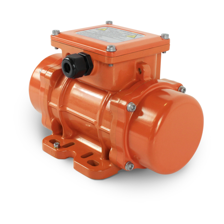
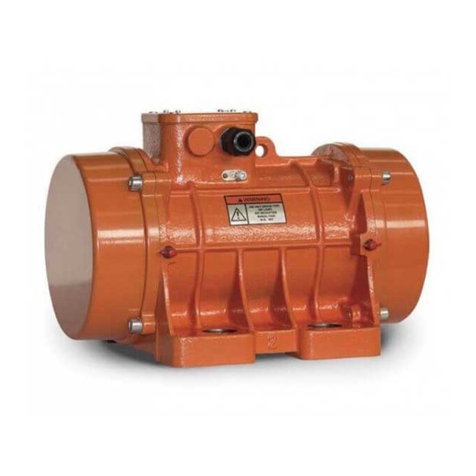
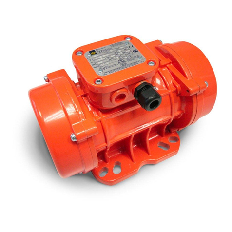
MVE DC electric vibrators are designed and constructed in accordance with the following applicable standards:
- CEI EN 60034-1 - EN 61241-0 - EN 61241-1
- Conformity to Directive 94/9 CE according to category3D, and to Directive 2006/42/CE
The general features of the MVE series of electric vibrators are listed below:
- Insulation Class F
- Standard tropicalization
- Protection IP 66
- Operating temperature: –20°C to + 40°C
Section 1 – GENERAL REGULATIONS
Read these instructions carefully before using the equipment,and keep the manual in a safe place for future reference. On receiving the product please
check that:
- the packing is not damaged to such an extent as to have damaged the product.
- there is no external damage to the product.
- the electrical supply corresponds to the order specications; non compliance and/or external damage, if any, must be reported immediately in detail
to the forwarding agent and the manufacturer and/or dealer.
Section 1.1 – IDENTIFICATION
The vibrator’s type and other various data are embossed on the identication plate.
This information must always be stated when requesting spare parts or a technical intervention.
Section 1.2 – USE OF THE VIBRATOR
WARNING: It is forbidden to operate the motor-vibrators described in this manual unless the machine or plant in which these are incorporated is declared
as conforming to the provisions of Directive 2006/42/EC.
The electric vibrator described in this Manual is designed and tested for use in potentially explosive zones classied as: zone 22 according to standard
EN 61241-10 and in accordance with ATEX Directive 94/9/CE.
The user must make sure that the workplace in which the electric vibrator is installed is set in safety condition from the point of view of risk of explosion.
To operate in safe conditions, check to make sure that the dusts have an ignition temperature higher than 75K of the surface temperature indicated on
the electric vibrator rating plate (EN61241-10).
(The maximum temperatures indicated in this Manual and on the electric vibrator rating plate are calculated without taking into consideration the
presence of layers of dust, if any, on the surface).
Its use for jobs dierent from those envisioned and non-conform to that described in this booklet, as well as being considered improper
and prohibited, releases the Manufacturer from any direct and/or indirect liability.
Section 2 – WARRANTY
The warranty is valid for manufacturing defects for a period of twenty-four(24) months from the date of purchase (attested by the delivery note
accompanying the goods).
The warranty covers all the mechanical parts and excludes electrical parts and those subject to wear. The warranty will be invalidated, thus freeing the
Manufacturer of any direct or indirect responsibility in the following cases: if the product is mishandled or used improperly, if repairs or modications
are made by unauthorised personnel, or if non-original spare partsare used.The material sent for repair under the warranty are returned CARRIAGE PAID.
Section 3 – SAFETY STANDARDS
f the customer observes the normal caution (typical of this kind of equipment) together with the indications contained in the manual“OPERATION AND
MAINTENANCE”, work is safe.The MVE motovibrator can be installed in any position. Fix the motovibrator on a sturdy surface to ensure that the vibrations
induced do not cause breakage or cracks: if this is not possible, use plates and ribbing for reinforcement. Cutting and welding procedures must be carried
out by qualied personnel. Suitable Hot-Works, (like cutting,welding…) and LOTO –lockout/tagout: procedure for disconnecting the machine (electrical
and mechanical segregation), must be applied for safe installation of the electric vibrator. Authorization for Hot works MUST be given by specialist trained
personnel familiar with the risk of explosion of powders.
The surface on which the machine is installed must be level and at (max 0.25mm/max 0.01) so that the feet rest uniformly and in perfect contact with
the surface, to avoid internal stresses which may cause breakage of the motovibrator feet.
The noise level of the electric vibrators measured IS NEVER greater than 76 dB(A)*
*Measured in normal operating conditions in accordance with standard UNI EN ISO 11202.
Section 3.1 – INSTALLATION
To x the motovibrator, use bolts (quality 8.8), nuts (quality 8.8) and at whasher A type UNI6592 Use a dynamometric wrench adjusted according to the
Table in data sheet. Remember that most of these problems and faults are caused by improper xing and locking.Anchor the motovibrator to the frame
by means of a suitable 15 cm long metal chain or cable.
Before starting up the vibrator, and after the rst 24 hours of operation, check:
- power the electric vibrator and using an ammeter pliers, check all phases to make sure the power draw does not exceed the value indicated on the
rating plate;
- the xing bolts of the motovibrator and the welds of the reinforcing plates and ribbing;
- the anchoring chain or cable;
- the power cable.
Section 4 – OPERATIVE NOTES
ELECTRICAL CONNECTIONS
THE ELECTRICAL CONNECTIONS MUST BE CARRIED OUT ONLY BYTRAINED PERSONNEL, AFTER DISCONNECTING THE POWER SUPPLY.
For the electrical connections refer to drawings.
The mains supply and motovibrator connections must conform to the existing safety standards dened by the competent authorities of the area in which
the operations are to be carried out.
- Check the mains supply voltage to ensure that it is the same as that indicated on the rating plate xed on the motovibrator.
- Disconnect the line before carrying out maintenance operations, or while adjusting the parts. Repair and replacement of components must be done
only by specialist personnel.
- For single-phase motovibrators, check the condenser to ensure it corresponds with the indications on the rating plate.
- Excessively long power cables cause voltage loss (follow the instructions of the standards). Check
When the motovibrators are installed in pairs, each of these must be provided with its own external overload protection, which must be interlocked
in order to prevent just one motovibrator from operating when the other stops accidentally. Always use magneto thermal cutout devices with delayed
action to prevent these from being activated during the start-up phase, when the current absorbed reaches very high levels (especially when the
temperature is very low).
Overload protection shall NOT BE HIGHER than 10% of the rating plate data; otherwise the warranty will be invalidated.
THE MOTOVIBRATOR MUST BE OPERATED ONLY BY QUALIFIED PERSONNEL.
All the electrical components the installer intends installing in the electric vibrator (such as overload protection, sensors…) must conform to ATEX
Directive 94/9/CE, II 3D or higher.
For connecting the electric vibrator in equipotential, connect the machine to earth using the special clamp provided on the body.
The environmental temperature where the machine is used is between –20°C and +40°C.
BLADE ADJUSTMENT
Disconnect the power supply to the motor-vibrator during disassembly and reassembly operations on the protection devices (mass cover).
After carrying out the operation on both sides, ret the covers using the same screw and washers taking care to make sure the gaskets are tted correctly
in their seats, as incorrect positioning can alter the degree of protection IP.
Section 5 – MAINTENANCE
The machine does not require maintenance.
Before carrying out any maintenance or cleaning on the machine, make sure it is set in safe conditions.
While removing the dust that may be present on the electric vibrator, take care to avoid its dispersal in the surroundings. Dust deposits must never exceed
a thickness of 5mm! Use only a damp cloth to remove the dust.
Section 6 – SPARE PARTS
For spare parts please refer to table.
Section 7 – RESIDUAL RISKS
Mechanical hazards
For maintenance operations, the operator must always use personal protection devices.
Presence of potentially hazardous powders
For carrying out routine and extraordinary maintenance operations, the operators must use special personal protection devices, and a mask, in particular,
to protect the respiratory tract belonging to a Class suitable for
the type of powder handled, in addition to protective gloves or clothing.
For more details, consult the safety chart of the powder handled by the appliance in which the electric vibrator is inserted.
Presence of harmful dusts
If the operator is required to work in the presence of harmful substance while handling the powders,for carrying out routine and special operations, he
must use suitable protective equipment as indicated in the safety chart of the product handled by the appliance in which the electric vibrator is inserted.
Section 8 – TROBLESHOOTING CHART
Refer to table.
Sezione 0 – DESCRIZIONE
I motovibratori MVE a corrente continua sono progettati e costruiti secondo le normative vigenti:
- CEI EN 60034-1 - EN 61241-0 - EN 61241-1
Conformità alla direttiva 94/9 CE secondo categoria 3D, e alla direttiva 2006/42/CE
Le caratteristiche generali dei motovibartori della serie MVE sono di seguito elencate:
- Classe isolamento F
- Tropicalizzazione di serie
- Protezione IP 66
- Temperatura di funzionamento: da –20°C a + 40°C
Sezione 1 – NORME GENERALI
Leggete attentamente queste istruzioni prima di utilizzare il vibratore e custodite questo manuale per futuri riferimenti.
Al ricevimento del prodotto controllate che:
- L’imballo non risulti deteriorato al punto di aver danneggiato il prodotto.
- Non vi siano danni esterni al prodotto.
- La fornitura corrisponda alle speciche dell’ordine; eventuali non conformità e/o danni esterni riscontrati dovranno essere segnalati immediatamente
in modo dettagliato sia allo spedizioniere che alla casa produttrice e/o rivenditore.
Sezione 1.1 – IDENTIFICAZIONE
Il modello del moto-vibratore e altri dati sono stampigliati sull’apposita targhetta di identicazione.
Questi dati devono essere sempre citati per eventuali richieste di parti di ricambio e per interventi di assistenza.
Sezione 1.2 – DESTINAZIONE D’USO
ATTENZIONE: è fatto divieto di mettere in servizio i moto-vibratori oggetto del presente manuale, prima che la macchina in cui saranno incorporati sia
stata dichiarata conforme alle disposizioni della direttiva 2006/42/CE
Il motovibratore elettrico descritto in questo manuale è stato progettato e testato per un utilizzo in zone potenzialmente esplosive classicate come:
zona 22 secondo la norma EN 61241-10 ed in accordo alla Direttiva ATEX 94/9/CE.
L’utilizzatore dovrà assicurarsi che il luogo di lavoro all’interno del quale verrà installato il motovibratore elettrico sia stato adeguatamente messo in
sicurezza da un punto di vista di rischio esplosione .
Per poter operare in condizioni di sicurezza occorre vericare che le polveri trattate abbiano una temperatura di accensione superiore a 75K della
temperatura superciale indicata sulla targhetta del motovibratore (EN61241-10).
(Le massime temperature indicate nel presente manuale ed in targa sui moto vibratori sono state calcolate senza considerare l’eventuale presenza di
strati dipolvere depositate sulle superci).
L’utilizzo dello stesso per impieghi diversi da quelli previsti e non conformi a quanto descritto in questo opuscolo, oltre ad essere
considerato improprio e vietato, scarica la Ditta Costruttrice da qualsiasi responsabilità diretta e/o indiretta.
Sezione 2 – GARANZIA
La garanzia è valida contro difetti di fabbricazione per un periodo di ventiquattro(24) mesi dalla data d’acquisto (fa fede il documento accompagnatorio
della merce). La garanzia copre tutte le parti meccaniche ed esclude quelle soggette ad usura e quelle elettriche.La garanzia decade, e con essa ogni
responsabilità diretta o indiretta, qualora il prodotto sia stato manomesso o utilizzato in modo improprio, siano state fatte riparazioni o modiche da
personale non autorizzato, siano stati utilizzati ricambi non originali.
I materiali resi per riparazione in garanzia vanno resi in PORTO FRANCO.
Sezione 3 – NORME DI SICUREZZA
Non vi è nessuna controindicazione all’uso, se vengono osservate le normali precauzioni per prodotti di questo tipo unitamente alle indicazioni riportate
nel manuale USO E MANUTENZIONE.
Il motovibratore MVE può essere installato in qualsiasi posizione. Si consiglia di ssare il motovibratore su una zona rigida per evitare che le vibrazioni
indotte provochino rotture o incrinature; se ciò non fosse possibile, è necessario utilizzare piastre e nervature di rinforzo. Le procedure di taglio e di
saldatura devono essere eettuate da personale qualicato. Idonee procedure di Hot-Works(quali taglio o saldatura) e LOTO-lockout/tagout:procedura
di disconnessione della macchina(segregazione elettrica e meccanica), dovranno essere applicate per l’installazione in sicurezza dl moto vibratore.
L’autorizzazione all’esecuzione dei lavori a caldo DEVE essere data da personale tecnico specializzato e formato sul rischio di esplosione da polveri.
La supercie di attacco deve essere piana (planarità max 0.25mm/max 0.01Inch) in modo che i piedi del vibratore appoggino uniformemente e siano a
perfetto contatto con la supercie di ssaggio, onde evitare tensioni interne capaci di portare alla rottura dei piedi del moto vibratore.
Il livello di pressione acustica continua equivalente ponderata dei moto vibratori NON è mai superiore ai 76 dB(A)*
Rilevazione eettuata in condizioni di normale funzionamento secondo la norma UNI EN ISO 11202.
Sezione 3.1 – INSTALLAZIONE
Per ssare il motovibratore, utilizzare bulloni (qualità 8.8), dadi (qualità 8.8) e rondelle piane cat.-A UNI6592. Utilizzare una chiave dinamometrica
regolata secondo quanto riportato nelle tabelle dati tecnici.
Ricordarsi che la maggior parte di guasti e avarie è dovuta a ssaggi e serraggi mal eseguiti.
Ancorare il motovibratore con adeguata catena di lunghezza cm. 15 o cavo metallico alla struttura.
Controllare prima della messa in marcia e dopo le prime 24 ore di lavoro:
- alimentare il vibratore e controllare con pinza amperometrica su tutte le fasi che l’assorbimento non superi il valore di targa;
- i bulloni di ssaggio del motovibratore e le saldature delle piastre e delle nervature di rinforzo;
- il cavo o catena di ancoraggio;
- il cablaggio di alimentazione.
Sezione 4 – NOTE OPERATIVE
COLLEGAMENTI ELETTRICI
IL COLLEGAMENTO ELETTRICO DEVE ESSERE EFFETTUATO ESCLUSIVAMENTE DA PERSONALE QUALIFICATO E CON ALIMENTAZIONE DISINSERITA.
Per i collegamenti dei moto vibratori fare riferimento allo schema.
La rete di alimentazione ed il collegamento dei motovibratori devono essere conformi alle vigenti norme di sicurezza stabilite dalle autorità competenti
del luogo dove si svolge l’attività.
- Accertarsi che la tensione di rete sia la stessa indicata sulla targhetta posta sul motovibratore
- Scollegare la linea prima di eseguire eventuali manutenzioni o durante la regolazione delle masse.
- Ogni riparazione o sostituzione di componenti deve essere eettuata solamente da personale specializzato.
- Cavi di alimentazione troppo lunghi causano cadute di tensione!!!! (attenersi a quanto prescritto dalle norme).
Quando i motovibratori vengono installati in coppia, ognuno di essi deve essere provvisto di una propria protezione esterna di sovraccarico, le quali
devono essere interbloccate tra loro, onde evitare il funzionamento di un solo motovibratore in caso di arresto accidentale dell’altro.
Utilizzare sempre magnetotermici ad intervento ritardato, in modo da evitarne l’intervento durante la fase di avviamento, nella quale la corrente
assorbita può raggiungere livelli elevati (soprattutto in presenza di basse temperature).
Protezione al sovraccarico NON SUPERIORE al 10% dei dati di targa, pena il decadimento della garanzia!
L’OPERAZIONE DEVE ESSERE ESEGUITA ESCLUSIVAMENTE DA PERSONALE QUALIFICATO.
Tutta la componentistica elettrica che l’installatore andrà ad inserire nel motovibratore elettrico (es. protezioni per il sovraccarico,sensori…) dovrà essere
conforme alla Direttiva ATEX 94/9/CE, II 3D o superiore.
Per il collegamento del moto vibratore in equipotenzialità, collegare la macchina a terra utilizzando l’apposito morsetto presente sulla carcassa.
La temperatura ambiente in cui la macchina opera è compresa tra -20°c/+40°c.
REGOLAZIONE DELLE MASSE
Durante le operazioni di smontaggio e montaggio delle parti di protezione (coperchi masse), togliere l’alimentazione del motovibratore.
Eseguita l’operazione su entrambi i lati, rimontare i coperchi con le stesse viti e rondelle facendo attenzione che le guarnizioni siano collocate
correttamente nelle propie sedi;un errato posizionamento potrebbe alterare il grado di protezione IP.
Sezione 5 – MANUTENZIONE
Il motovibratore non richiede manutenzione. Pulizia: prima di eettuare un qualsiasi intervento di manutenzione o pulizia sulla macchina assicurarsi
che questa sia messa in sicurezza. Gli strati di polvere depositata non deve mai superare i 5 mm di spessore, pulire con l’ausilio di un panno umido. Non
dirigere direttamente getti d’acqua ad alta pressione sul moto vibratore elettrico.
Sezione 6 – RICAMBI
Per le parti di ricambio fare riferimento alla tabella.
Sezione 7 – RISCHI RESIDUI
Pericoli di natura meccanica
Per le attività di manutenzione è fatto obbligo all’operatore di impiegare sempre i dispositivi di protezione individuale.
Presenza di polveri potenzialmente pericolose
Nel caso di interventi sia ordinari che straordinari di manutenzione l’operatore deve dotarsi di idonei dispositivi di protezione individuale ed in particolare
utilizzare maschere a protezione delle vie respiratorie di classe idonea in base al tipo di polvere trattata nonché di guanti o indumenti. Per maggiori
dettagli si deve far riferimento alla scheda di sicurezza prodotto trattato dall’apparecchiatura nel quale il moto vibratore è inserito.
Presenza di polveri nocive
In determinati trattamenti di polveri dove vi è la presenza di sostanze nocive, l’operatore che dovesse accedere, nel corso di interventi ordinari e
straordinari,deve indossare gli idonei dispositivi di protezione come indicato nella scheda di sicurezza prodotto trattato dall’apparecchiatura nel quale
il moto-vibratore è inserito.
Sezione 8 – GUASTI E ANOMALIE
Fare riferimento alla tabella.
SHORT INSTALLATION AND OPERATING
INSTRUCTIONS FOR VIBRATORS
MVE DC
ISTRUZIONI BREVI PER L’INSTALLAZIONE E
L’USO DEI VIBRATORI
CODE: OLMVEDCITEN01 | DATE: 07/2010

