manuals.online logo
Brands
  1. Home
  2. •
  3. Brands
  4. •
  5. WAREMA
  6. •
  7. Control Unit
  8. •
  9. WAREMA MSE Haustechnik ZL User manual

WAREMA MSE Haustechnik ZL User manual

1
warema_890591_alhb_en_v9•2022-09-01 We reserve the right to make technical modifications
General information
Fig. 1 MSE Haustechnik ZL
The MSE Haustechnik ZL is an electronic control unit for
the direct control of 230V AC sun shading system drives.
This motor control unit is equipped with a time logic func-
tion that allows for convenient operation of your sun shad-
ing system. Because of its compact design, the MSE can
be accommodated in a flush-mounted junction box. The
motor and the MSE are supplied via the power line. The
sun shading control system can be operated via local push
buttons and via a higher level central control unit. Several
motor control units can be combined into a group and
controlled jointly from a push button.
Intended use
The MSE Haustechnik ZL was developed to control sun
shading systems. The approval of the manufacturer must
be obtained for uses outside of the purposes listed in
these instructions.
Safety information
WARNING
The electrical installation (assembly)/dis-
mantling must be performed by a certified
electrician in accordance with the elec-
trical installation regulations published
by the VDE Association for Electrical,
Electronic & Information Technologies
(VDE 0100) or the standards and regula-
tions of the country in which the device
is being installed. The specialist must ob-
serve the installation instructions included
with the electrical device.
WARNING
If hazard-free operation cannot be as-
sumed, the device may not be started or
must be deactivated. This assumption is
justified if
 The housing or the supply lines show signs
of damage,
 The device is no longer working.
WARNING
It is important to comply with the following
points in the interest of personal safety.
Children may not play with the operating elements of the
control unit or the remote control. Store the remote con-
trols out of the range of children.
Make sure that no persons or objects are in the range of
movement of the driven parts (blinds, window, etc.).
Disconnect the MSE from the supply voltage if cleaning or
other maintenance work must be performed.
Function of the MSE Haustechnik ZL
Local operation
After the local operating element is actuated, the sun
shading product moves in the corresponding direction and
stops after 2 seconds. If the "UP/DOWN" button continues
to be pushed, the MSE switches to lock mode. The button
may then be released. The sun shading product moves
to the UP or DOWN limit position. If the movement should
stop in lock mode, the button for the opposite direction of
movement must be pressed briefly.
Central operation
Local operation is disabled for the duration of the central
command; if lock mode is active, it is cleared.
I
f the drive does not reach the "UP" or "DOWN"
limit switch within 3 minutes, the drive is cut off
automatically, regardless of whether a local or a
central move command was applied.
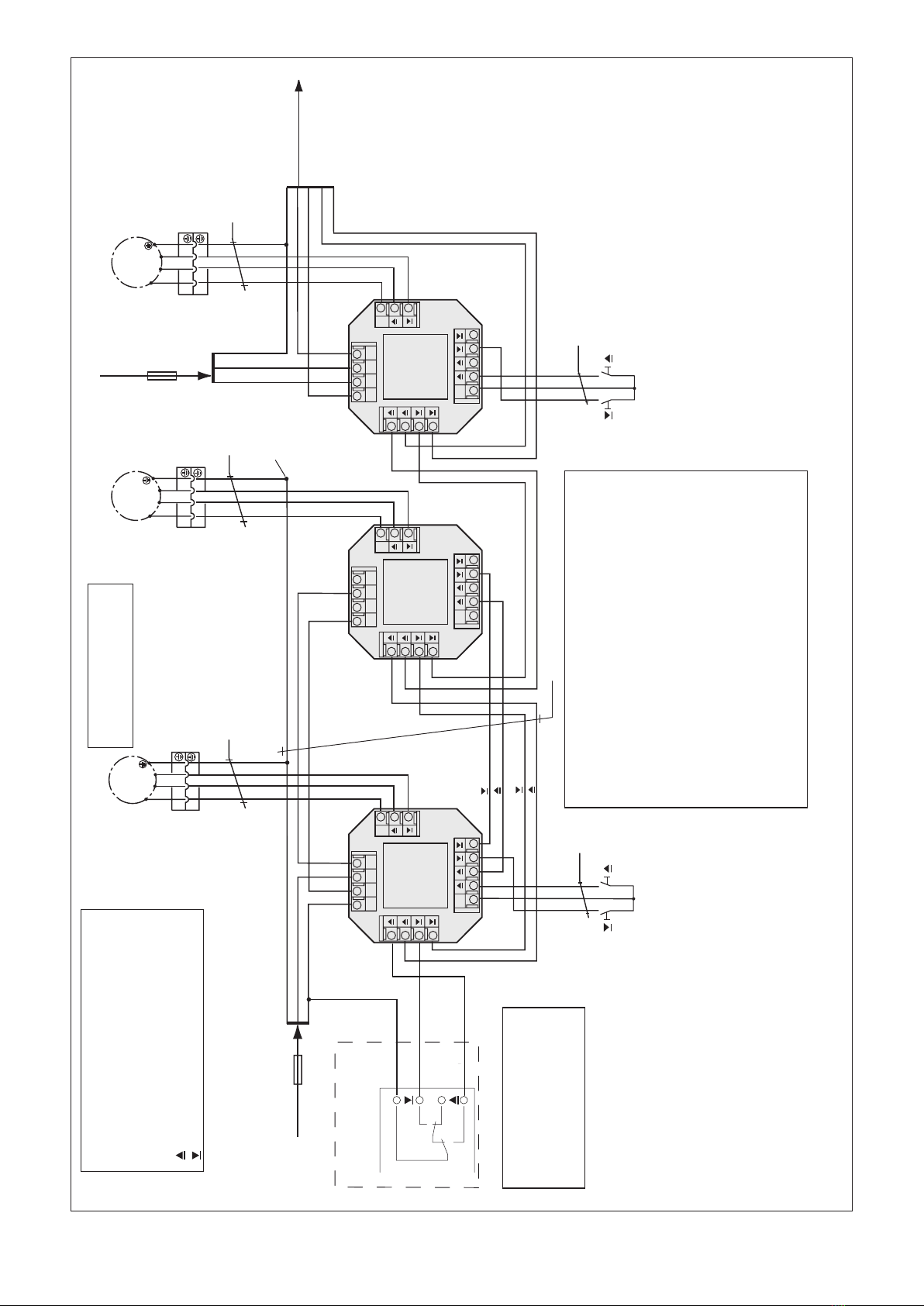
Grouping via the control line
Several MSE can be combined to a group via the shared
control line and operated centrally via an operating ele-
ment. Refer to Fig.5 (wiring diagram).
Multiple outside lines (phases) may be used in a
system if they are fed through a common earth
leakage circuit breaker.
Valid as of
1 September 2022
Keep for future use.
MSE Haustechnik ZL
Operating and installation instructions
warema_890591_alhb_en_v9•2022-09-01We reserve the right to make technical modifications
2
Installation
The MSE Haustechnik ZL (Fig.3) is intended for flush
mounting in a commercially available deep flush-mounted
switch box; installation in a deep flush-mounted junction
box with a diameter of 70mm/56mm is recommended.
Only such lines as are used for the wiring of the motor
control unit should be routed into this box. Alternatively, the
MSE can be supplied in a surface-mounted housing (not
for outdoor use, Fig.4).
Installation must be indoors. The device is not suitable for
use in damp interiors. The electrical connection of the mo-
tor control unit is performed using spring terminals (Fig.2)
according to the wiring diagram on the reverse (see Fig.5).
Handling the spring terminals
Fig. 2 Connecting and disconnecting the line connections
After the wire is stripped, it is pressed into the terminal (1)
until the insulation on the wire enters the terminal and the
line is securely held in the terminal (2). To disconnect the
line, the appropriate unlock button needs to be pressed in
as far as it will go using a screw driver, and the line then
removed from the terminal (3).
Electrical installation
An on-site overload current protection device (fuse) and a
disconnecting and isolating switch to switch off the entire
system must be provided.
Initial operation
After the device is fully mounted and the power supply is
connected, the device is ready for operation.
Maintenance
There are no parts within the device that require mainte-
nance. In the event of a malfunction, the miniature fuses
may only be exchanged by an certified electrician!
Cleaning
Clean the housing with a soft, dry cloth. Do not use deter-
gents, cleaning agents, solvents, abrasive substances or
steam cleaners!
Liability
Failure to comply with the product information in these
instructions and use of the device in a manner that con-
travenes its intended use and purpose may result in the
manufacture refusing to honour warranty claims for prod-
uct damage. In this case, liability for consequential harm
to persons or damage to property will also be excluded.
Follow also the instructions in the operating manual of your
sun shading system. The automatic or manual operation of
the sun shading system when iced over as well as using
the sun shading system during severe weather may cause
damages and must be prevented by the user by taking suit-
able precautions.
Obligations for the disposal of electrical devices
A marking with this symbol indicates the following
obligations under the scope of legal regulations:
 The owner of this electrical device must dispose of it
separately from unsorted municipal waste for further
recycling.
 Used batteries and accumulators that are not enclosed
in the old device, as well as lamps/bulbs that can be
removed from the old device without breaking, must be
disposed of separately.
 Distributors of electrical devices and disposal compa-
nies are obliged to take back the equipment free of
charge.
 The owner must take it upon themselves to delete any
personal data contained in the electrical device prior to
disposal.
3
warema_890591_alhb_en_v9•2022-09-01 We reserve the right to make technical modifications
Technical data
MSE Haustechnik ZL Min. Typ. Max. Unit
Supply 230 V~, 50 Hz
Operating voltage 207 230 253 V AC
Power consumption 1 VA
Drive output
Switching capacity at
230 V∼/cos ϕ = 0.6
700 VA
Input control
Central voltage active 207 230 253 V AC
Central current active 1 1.5 2 mA
Central voltage inactive -0.5 0 4 V AC
Local voltage active 103 115 126 V DC
Local current active 1 1.5 2 mA
Local voltage inactive -0.5 0 4 V DC
Enclosure
Dimensions Installation in flush-mounted
box, see Fig. 3
Surface-mounted housing, see
Fig.4
Degree of protection/safety class
In flush-mounted box
In surface-mounted
housing
IP 20
IP 54
Protection class
(without PE)
II
Connection
All connections Spring terminals
Terminals
Power line,
drive line
0.5...1.5 mm2
Control line,
Push button line
0.5...1.5 mm2
Miscellaneous
Conformity
Viewable at www.warema.de/ce
This device complies with the EMC directives for use in
residential and commercial areas.
Ambient conditions
Operating temperature 0 20 40 °C
Storage temperature 0 20 50 °C
Rel. humidity
(non-condensing)
10 40 85 %RH
Degree of soiling 2
Article numbers
MSE Haustechnik
ZL UP
MSE Haustechnik
ZL AP
1002415
1002422
WAREMA Renkhoff SE
Hans-Wilhelm-Renkhoff-Strasse 2
97828 Marktheidenfeld
Germany
20.4 mm
26.0 mm 48.0 mm
48.0 mm
Fig. 3 MSE Haustechnik ZL for installation in a flush-mounted
box
88
88
53
Fig. 4 Surface-mounted housing of the MSE Haustechnik ZL
warema_890591_alhb_en_v9•2022-09-01We reserve the right to make technical modifications
4
LLNN
X1
N
Motor
230V
X2
P
Lokal
230V
X3
X4
Zentral
230V
Central UP
230 V AC
Central DOWN
230 V AC
Netz
230V
MSE Haus-
technik
ZL
LLNN
X1
N
Motor
230V
X2
P
Lokal
230V
X3
X4
Zentral
230V
Netz
230V
LLNN
X1
N
Motor
230V
X2
P
Lokal
230V
X3
X4
Zentral
230V
Netz
230V
1
1
2
2
3
123
M 1~
1
1
2
2
3
3
123
1
1
2
2
3
3
123
Group
Central
Group
Terminal
PE
L1
N
PE
L2
L2 PE
N
N
Plug-and-socket connection
MSE Haus-
technik
ZL
MSE Haus-
technik
ZL
Central UP
Central DOWN
Supply line (2.Phase)
230V AC 50 Hz / 6 A
(1*)
Motor 1
Legend:
 NYM-J 7 x 1,5
NYM-J 5 x 1,5
 NYM-J 3 x 1,5
 H05RR-F 4 G 0,75
BK, Type WAREMA
DOWN
UP
3
 
M 1~
Motor 2
M 1~

BK BNBL GNYE
Group pushbutton
(Motor 1 + 2)
PP
Single pushbutton
(Motor 3)
Motor 3
Supply line
230 V AC 50 Hz / 6 A
(3*)
F

Supply line
230 V AC
to next MSEs

Connection:
Floating contacts of the
sun shading control system/
GA Compact
E
P/C
For further information, see
documentation to wiring
diagrams "Anschlusspläne"
Art.No:
816 345
Central
L1



- Max. group size of 30 motor control units, see voltage drop diagram.
- Central control line length, see voltage drop diagram.
- The power line length is limited by the total motor current. The
maximum number of drives per circuit depends on their current
consumption and the upstream fuse.
- Max. switching capacity of the MSE: see "Technical data".
- Only pushbuttons may be used.
(1*) When grouping, 7 x 1.5 mm² must be routed between the MSE!
(2*)
The push button may only be connected to "P". The Terminal "P" may
not be looped through. Don’t connect 230 V AC to Terminal "P".
Attention!
The line length to a group push button or single push button is
max. 25 metres.
(3*) Multiple outside lines (phases) may be used within a single system
if they are passed through a shared
earth leakage circuit breaker.
A max. of 5 drives with a rated motor current of 1 A may be
connected to a B6A inline circuit breaker.
Attention!
All circuits must be switched off for maintenance work.
(2*)
(3*)
(2*)
BK BNBL GNYE BK BNBL GNYE
Attention!
Only one drive may be
connected per MSE!
Fig. 5 MSE Haustechnik ZL wiring diagram

Other WAREMA Control Unit manuals

WAREMA GA Kompakt User manual

WAREMA

WAREMA GA Kompakt User manual

WAREMA climatronic WebControl User manual

WAREMA

WAREMA climatronic WebControl User manual

WAREMA MSE Compact 1 UP User manual

WAREMA

WAREMA MSE Compact 1 UP User manual

WAREMA WMS WebControl User manual

WAREMA

WAREMA WMS WebControl User manual

WAREMA Omnexo User manual

WAREMA

WAREMA Omnexo User manual

WAREMA WMS WebControl pro User manual

WAREMA

WAREMA WMS WebControl pro User manual

WAREMA WMS Splitter UP User manual

WAREMA

WAREMA WMS Splitter UP User manual

WAREMA GA Kompakt User manual

WAREMA

WAREMA GA Kompakt User manual

WAREMA Uniswitch ZL User manual

WAREMA

WAREMA Uniswitch ZL User manual

WAREMA Minitronic Dialog User manual

WAREMA

WAREMA Minitronic Dialog User manual

WAREMA MSE Compact 2 REG User manual

WAREMA

WAREMA MSE Compact 2 REG User manual

WAREMA GA Kompakt User manual

WAREMA

WAREMA GA Kompakt User manual

Popular Control Unit manuals by other brands

Nexo GEO S12 EN54 Series System manual

Nexo

Nexo GEO S12 EN54 Series System manual

Rabbit RCM3365 user manual

Rabbit

Rabbit RCM3365 user manual

Keysight Technologies E8257DS Series user guide

Keysight Technologies

Keysight Technologies E8257DS Series user guide

ControlByWeb DAQ Series user manual

ControlByWeb

ControlByWeb DAQ Series user manual

SMC Networks AKP Series Operation manual

SMC Networks

SMC Networks AKP Series Operation manual

Veethree VeeCAN 320 instructions

Veethree

Veethree VeeCAN 320 instructions

Burkert 2657 operating instructions

Burkert

Burkert 2657 operating instructions

Festo VPPL operating instructions

Festo

Festo VPPL operating instructions

A-T Controls Triac TMC-4 Installation and operation manual

A-T Controls

A-T Controls Triac TMC-4 Installation and operation manual

Trenz Electronic TEI0003 Schematics

Trenz Electronic

Trenz Electronic TEI0003 Schematics

Thrane&Thrane SAILOR 630 Series installation guide

Thrane&Thrane

Thrane&Thrane SAILOR 630 Series installation guide

KIESELMANN 5091 Operating	 instruction

KIESELMANN

KIESELMANN 5091 Operating instruction

Meinberg IMS-GNS181-UC Setup guide

Meinberg

Meinberg IMS-GNS181-UC Setup guide

Wilo Stratos PLR Installation and operating instructions

Wilo

Wilo Stratos PLR Installation and operating instructions

Anttron TRM84 user manual

Anttron

Anttron TRM84 user manual

Intel RMS25KB080 Quick start user guide

Intel

Intel RMS25KB080 Quick start user guide

Lamtec ETAMATIC manual

Lamtec

Lamtec ETAMATIC manual

Lauterbach mTrace Setup guide

Lauterbach

Lauterbach mTrace Setup guide

manuals.online logo
manuals.online logoBrands
  • About & Mission
  • Contact us
  • Privacy Policy
  • Terms and Conditions

Copyright 2025 Manuals.Online. All Rights Reserved.