manuals.online logo
Brands
  1. Home
  2. •
  3. Brands
  4. •
  5. WAREMA
  6. •
  7. Control Unit
  8. •
  9. WAREMA GA Kompakt User manual

WAREMA GA Kompakt User manual

1
warema_816835_alhb_en_v4•2022-04-01 We reserve the right to make technical modifications
Operating and installation instructions
GA Kompakt
Valid from
1 April 2022
Keep for future use.
General
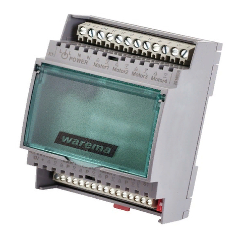
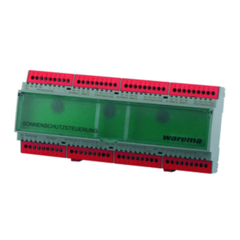
Fig. 1 GA Kompakt REG
The floor distribution control (GA) enables the central
control of the motor control units of a floor. The control
signals from the sun shading control system are forwarded
to all motor control units of a floor. The sunshade drives
of this floor can be distributed to up to four facades via
the GA and controlled separately. In addition, four facade
push buttons can be connected to the GA, which enables
the connected motor control units to be jointly operated for
each facade.
Intended use
The device was developed to control sun shading sys-
tems. The approval of the manufacturer must be obtained
for uses outside of the purposes listed in these instruc-
tions.
Safety instructions
ARNINGW
The electrical installation (assembly)/
dismantling must be performed by a cer-
tified electrician in accordance with the
electrical installation regulations published
by the Association of German Electrical
Engineers (VDE 0100) or the standards
and regulations of the country in which
the device is being installed. The specialist
must observe the installation instructions
included with the electrical device.
ARNINGW
If hazard-free operation cannot be
assumed, the device may not be started or
must be deactivated. This assumption is
justified
 If the housing or the supply lines show signs
of damage,
 The device is no longer working
ARNINGW
It is important to comply with the follow-
ing instructions in the interest of personal
safety!
■Do not allow children to play with the operating elements
of the control or remote control. Store the remote controls
out of range of children.
■Make sure that no persons or objects are in the range of
movement of the driven parts (blinds, window, etc.).
■Disconnect the device from the supply voltage if cleaning
or other maintenance work must be performed.
Function
Move commands from the local facade push buttons are
forwarded to the connected motor control units via the
GA Kompakt. After the button is pressed, the sun shad-
ing system moves in the corresponding direction and
stops after two seconds. If the button is pressed for more
than two seconds, the control will stay activated automati-
cally. The button may then be released. The sun shading
system moves until the fixed run time of three minutes has
expired. In order to clear the locked state and stop the
motor, briefly press the button for the opposite direction of
movement. The move commands from a sun shading con-
trol system have priority over the move commands from
the facade push buttons and are directly forwarded to the
motor control units. Operation via the facade push button
is blocked during a central command.
Installation
The motor control unit is, depending on the selected meth-
od of installation, designed for surface mounting (AP) or
for installation in a distributor (REG).
 AP: Insert a slotted screwdriver
(recommendation: 3.0 - 4.0mm blade) into
the respective cover opening (see Fig. 4)
and carefully pry the folding cover open.
Repeat the procedure for the second
opening of the cover. The cover can be
folded up when both catches have been
released. The second cover can be opened
in the same manner. Alternatively, the
surface-mounted variant can be mounted
on a DIN rail (TH 35-15).
warema_816835_alhb_en_v4•2022-04-01We reserve the right to make technical modifications
2
 REG: When installing the device in a distributor,
clip it onto a symmetrical DIN rail (TH35-
15). To ease connecting the device, the ter-
minal covers can be removed (see Fig. 2).
One of the terminal covers can be removed
to connect the network.
Remove the terminal covers:
Insert a suitable screwdriver
into the notch.
Fig. 2 Removing the terminal covers (REG variant)
 The electrical connection of the motor
control unit is established according to the
wiring diagram on the back (see Fig. 6).
Electrical installation
An on-site overload current protection device (fuse) and a
disconnecting and isolating switch to switch off the entire
system must be provided.
The device meets the EMC directives for use in residential
and commercial areas.
Commissioning
The device is operational after the installation has been
completed and the supply voltage applied.
Maintenance
There are no parts within the device that require mainte-
nance.
Cleaning
Clean the housing with a soft, dry cloth. Do not use deter-
gents, cleaning agents, solvents, abrasive substances or
steam cleaners!
Liability
The liability for consequential damage to persons or
property is excluded if the device is used for any purpose
other than those described in these instructions. Observe
the information in the operating instructions for your sun
shading system. Liability is also excluded for damage to
the sun shading system resulting from operation under icy
conditions.
Obligations for the disposal of electrical devices
A marking with this symbol indicates the following
obligations under the scope of legal regulations:
 The owner of this electrical device must dispose of it
separately from unsorted municipal waste for further
recycling.
 Used batteries and accumulators that are not enclosed
in the old device, as well as lamps/bulbs that can be
removed from the old device without breaking, must be
disposed of separately.
 Distributors of electrical devices and disposal compa-
nies are obliged to take back the equipment free of
charge
.
 The owner must take it upon themselves to delete any
personal data contained in the electrical device prior to
disposal.
Technical data
GA Kompakt Min. Typ. Max. Unit
Supply 230 V AC
Operating voltage 198 230 253 V AC
Current consumption,
primary 12 14 16 mA
Floating output
DC switching voltage per
facade 24 36 V DC
AC switching voltage per
facade 230 253 V AC
Switching capacity per fa-
cade 230 V AC/cos ϕ =0.6
700 VA
Switching capacity per
facade 72 W
Control per facade
Central voltage active 8 24 36 V DC
Central current active 0.2 1 1.5 mA
Central voltage inactive –0.5 0 1.5 V DC
Local voltage active 8 24 36 V DC
Local current active 1 1.5 2 mA
Local voltage inactive -0.5 0 1.5 V DC
Run time, up/down 3 min
Enclosure
Dimensions See Fig. 3, 4
Degree of protection/safety class
Degree of protection
(REG/AP housing) IP30
Safety class I
Ambient conditions
Operating temperature -5 20 40 °C
Storage temperature -20 20 80 °C
Humidity
(not condensing) 10 40 85 %RH
Degree of soiling 2
Connection
All connections Screwed terminals
Terminals
All terminals 0.5 ... 2.5 mm2
Miscellaneous
Conformity
Available at www.warema.de/ce
This device complies with the EMC directives for use in
residential and commercial areas.
Article number
GA Kompakt in AP hous-
ing 1002 743
GA Kompakt in REG
housing 1002 628
WAREMA Renkhoff SE
Hans-Wilhelm-Renkhoff-Strasse 2
D-97828 Marktheidenfeld
3
warema_816835_alhb_en_v4•2022-04-01 We reserve the right to make technical modifications
210 mm**
158 mm
180 mm
60 mm
119 mm
184 mm*
132 mm
-
* 4M: 132mm
6M: 184mm
**4M: 158mm
6M: 210mm
Fig. 3 AP housing
60 mm
95 mm
90 mm
210 mm / 12 MW
60 mm
Fig. 4 REG housing
warema_816835_alhb_en_v4•2022-04-01We reserve the right to make technical modifications
4
PE
0V
0V
+
+
Fassade 1
Fassade 1
Fassade 2
Fassade 2
Fassade 3
Fassade 3
Fassade 4
Fassade 4
Facade 1
Facade 1
Facade 2
Facade 2
Facade 3
Facade 3
Facade 4
Facade 4
P
PE
Facade1 Central
PE NLL
91 876543912 8765439128765439128765432
192345678 1923467198234678 123465
X1
X7
N
N
L
PE
L
N
Power line provided
by customer
230V AC / 50Hz/16A
3x1,5mm
2
Power line provided
by customer
230V AC / 50Hz/16A
3x1,5mm
2
To next
GA Kompakt
Push button facade 1
To next
GA Kompakt
To next
MSE Kompakt
GA
Kompakt
Attention! Connectioon „0“ and „+“ of
terminal strip X7 must be looped through
to each GA.
PE
- Facade 1 --2Facade-Network
X3
- Single
operation-
-- 0V - terminals --
X5
0V 0V 0V 0V 0V 0V
X6
All push button lines
JY(St)Y 2x2x0,8 mm ø
Loop cable
Central control
JY(St)Y 8x2x0,8 mm ø
21
P
0
21
P
0
21
P
0
PE PE
- Facade 3 --Facade 4 -
PE
+24V
0V
To next
MSE Kompakt I
JY(St)Y 4x2x0,8 mmø
Power line provided
by customer
230V AC / 50Hz/10A
3x1,5mm
2
0V +P
X8
0V +P
X9
0V +P
X10
0V
+
PE
N
L1
00++ P
NPE NN L1
0V +24V
MSE
Kompakt I
3,15 AT
PE
N
L1
+24V
Power line provided
by customer
230V AC / 50Hz/16A
3x1,5mm
2
To next
MSE Standard
To next
MSE Standard
JY(St)Y 4x2x0,8 mmø
E
0
PE
N
L1
00 EE P
NPE NN L1
MSE
Standard
Power supply
unit Universal
3,15 AT
PE
N
L1
E
L1
N
1243
4312
L1
N
L1
N
PE PE
control
Facade 2 Central
control
- Single
operation-
Facade 3 Central
control
- Single
operation-
Facade 4 Central - Single
operation-
Push button facade 2 Push button facade 3 + 4
Fig. 5 Connection example of the floor distribution control with MSE Kompakt I and MSE Standard. For additional wiring diagrams, see
"Wiring diagrams for MSE, power supply units and GA", art. no. 816345.

Other WAREMA Control Unit manuals

WAREMA Omnexo User manual

WAREMA

WAREMA Omnexo User manual

WAREMA WMS Splitter UP User manual

WAREMA

WAREMA WMS Splitter UP User manual

WAREMA MSE Compact 1 UP User manual

WAREMA

WAREMA MSE Compact 1 UP User manual

WAREMA GA Kompakt User manual

WAREMA

WAREMA GA Kompakt User manual

WAREMA GA Kompakt User manual

WAREMA

WAREMA GA Kompakt User manual

WAREMA MSE Compact 2 REG User manual

WAREMA

WAREMA MSE Compact 2 REG User manual

WAREMA WMS WebControl pro User manual

WAREMA

WAREMA WMS WebControl pro User manual

WAREMA Minitronic Dialog User manual

WAREMA

WAREMA Minitronic Dialog User manual

WAREMA Uniswitch ZL User manual

WAREMA

WAREMA Uniswitch ZL User manual

WAREMA WMS WebControl User manual

WAREMA

WAREMA WMS WebControl User manual

WAREMA MSE Haustechnik ZL User manual

WAREMA

WAREMA MSE Haustechnik ZL User manual

WAREMA climatronic WebControl User manual

WAREMA

WAREMA climatronic WebControl User manual

Popular Control Unit manuals by other brands

Vision Audio Visual TECHCONNECT TC3 HDMITP2 owner's manual

Vision Audio Visual

Vision Audio Visual TECHCONNECT TC3 HDMITP2 owner's manual

Stone STWI070WT-01 Equipment manual

Stone

Stone STWI070WT-01 Equipment manual

EMAC SoM-210ES user manual

EMAC

EMAC SoM-210ES user manual

Solaria PowerXT-395R-PM Safety, installation, and operation manual

Solaria

Solaria PowerXT-395R-PM Safety, installation, and operation manual

PROPOINT 8688848 quick start guide

PROPOINT

PROPOINT 8688848 quick start guide

ETAS XETK-V2.0 Series user guide

ETAS

ETAS XETK-V2.0 Series user guide

Bosch Rextroth Indramat RECO R-IB IL CNT Applications manual

Bosch

Bosch Rextroth Indramat RECO R-IB IL CNT Applications manual

IBASE Technology ET930 user manual

IBASE Technology

IBASE Technology ET930 user manual

Emerson Fisher Design GX Series instruction manual

Emerson

Emerson Fisher Design GX Series instruction manual

Linn AKTIV Crossover owner's manual

Linn

Linn AKTIV Crossover owner's manual

CCS PJ Series Instruction guide

CCS

CCS PJ Series Instruction guide

Ricoh Shepherd-P1 Technical bulletin

Ricoh

Ricoh Shepherd-P1 Technical bulletin

Arbor Technology Qseven EmQ-i230J user manual

Arbor Technology

Arbor Technology Qseven EmQ-i230J user manual

Wilo Control EC-Fire Installation and operating instructions

Wilo

Wilo Control EC-Fire Installation and operating instructions

quiko QK-CE24BAT user manual

quiko

quiko QK-CE24BAT user manual

Watts 757 Series Installation, maintenance & repair

Watts

Watts 757 Series Installation, maintenance & repair

Seneca Z-PC SERIES installation manual

Seneca

Seneca Z-PC SERIES installation manual

ADLINK Technology cPCI-R6100 user manual

ADLINK Technology

ADLINK Technology cPCI-R6100 user manual

manuals.online logo
manuals.online logoBrands
  • About & Mission
  • Contact us
  • Privacy Policy
  • Terms and Conditions

Copyright 2025 Manuals.Online. All Rights Reserved.