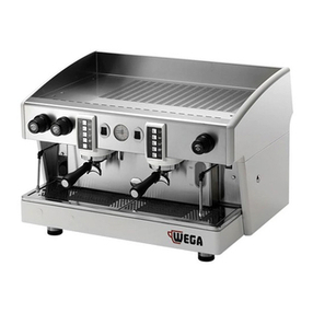
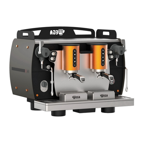
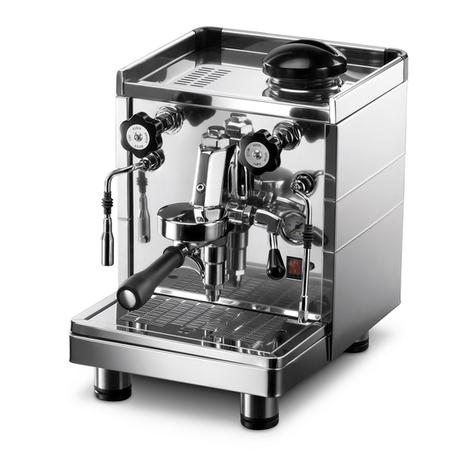
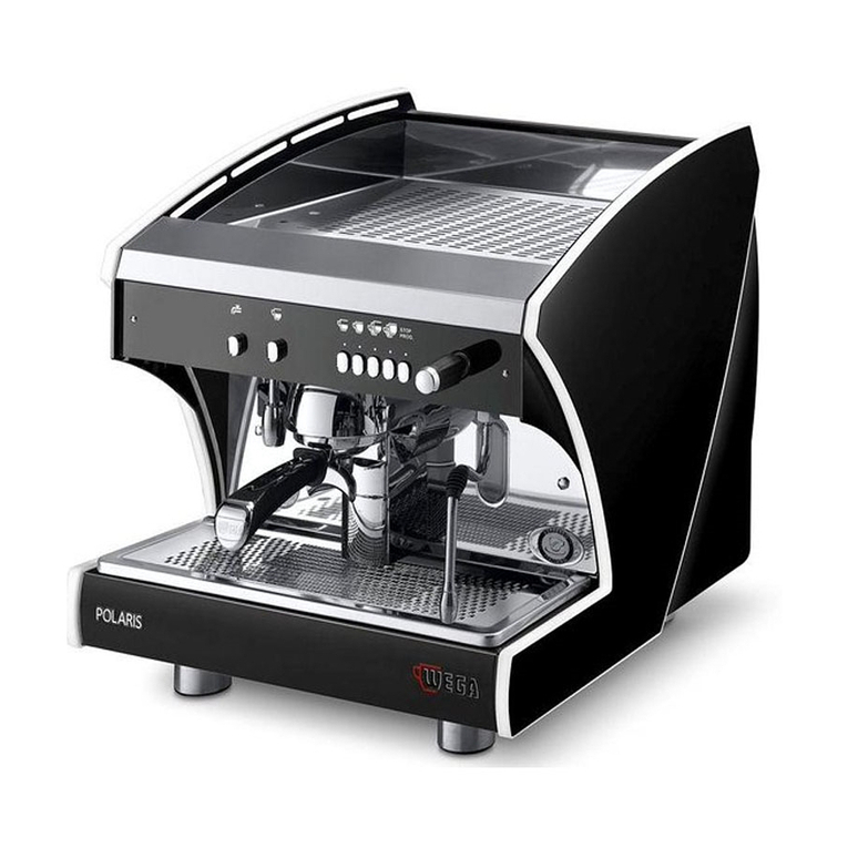
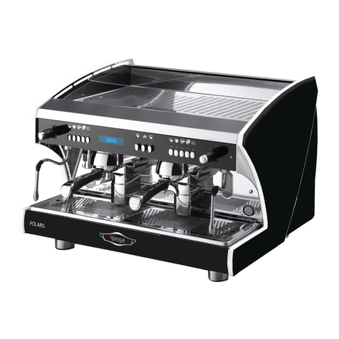
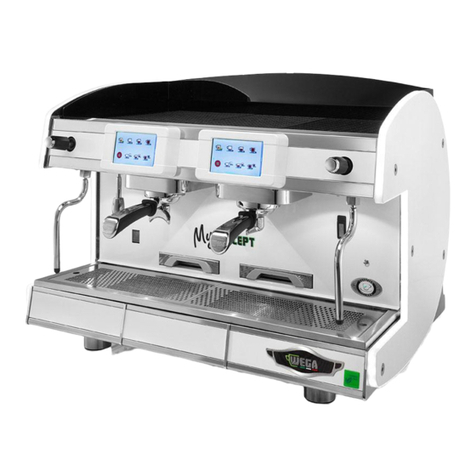
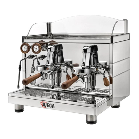
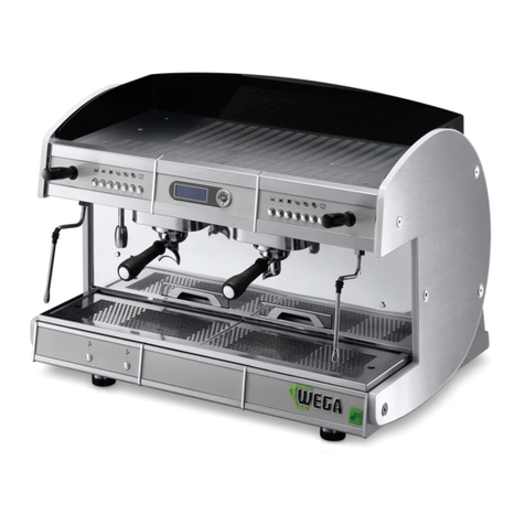
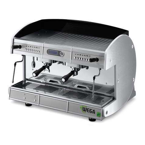
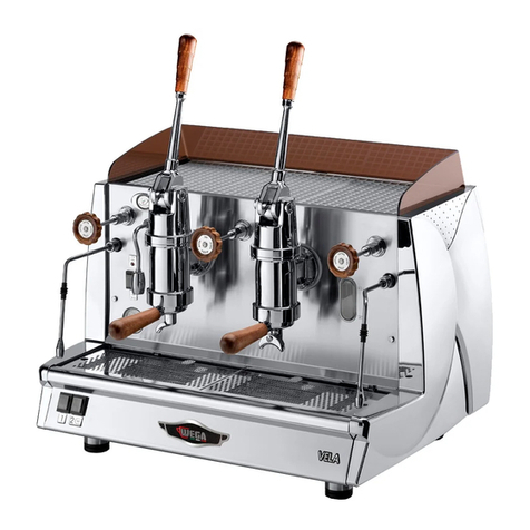
Wega ALE Series User manual

WEGA MACCHINE PER CAFFÈ S.r.l.
Via Condotti Bardini, 1 - 31058 SUSEGANA (TV) - ITALY - Tel. +39.0438.1799700 - Fax +39.0438.1884890 - www.wega.it - info@wega.it
2006/42/CE Machinery Directive
ALE
EMA
EPU
EVD
DISPLAY
ESPRESSO COFFEE MACHINE
Use and maintenance manual. TECHNICIANS instructions. EN

IMPORTANT: Read carefully before use - Store for future reference
Content rights The partial reproduction and dissemination of the contents in this document without the prior written consent
of the Manufacturer is forbidden. The Company logo is owned by the Manufacturer of the Machine.
Responsibility We are constantly striving to improve the accuracy of the information published in each Manual, but there
may be some inaccuracies. We assume no responsibility for any errors or omissions, or for damages resulting from the use of
this document.

ESPRESSO COFFEE MACHINE
Use and maintenance manual. TECHNICIANS instructions.
English
Summary
1. INTRODUCTION.................................................................4
1.1 Guidelines for reading the Manual........................................ 4
1.2 Storing the Manual ............................................................... 4
1.3 Method for updating the Instruction Manual........................ 5
1.4 Recipients ............................................................................. 5
1.5 Glossary and Pictograms....................................................... 5
1.6 Guarantee ............................................................................. 6
1.7 Customer service................................................................... 6
2. IDENTIFICATION OFTHE MACHINE...........................................7
2.1 Make and model designation................................................ 7
2.2 General description............................................................... 7
2.3 Intended use......................................................................... 7
2.4 Machine description ............................................................. 8
2.5 Internal components............................................................. 9
2.6 Data and CE marking........................................................... 10
3. TRANSPORT AND HANDLING ................................................18
3.1 Safety precautions .............................................................. 18
3.2 DPI characteristics............................................................... 18
3.3 Weight................................................................................ 18
3.4 Handling the packed machine............................................. 18
3.5 Unpacking the machine ...................................................... 18
4. STORAGE ..............................................................................19
4.1 Overview............................................................................. 19
4.2 Storing the machine after the operation............................. 19
5. INSTALLATION ......................................................................19
5.1 Safety precautions .............................................................. 19
5.2 DPI characteristics............................................................... 20
5.3 Environmental conditions ................................................... 20
5.4 Installation space and operating space ............................... 20
5.5 Support base....................................................................... 20
5.6 Drilling the support base..................................................... 22
5.7 Hydraulic connection .......................................................... 23
5.8 Electrical connection........................................................... 24
5.9 Gas connection (if included)................................................ 25
6. COMMISSIONING..................................................................29
6.1 Safety precautions .............................................................. 29
6.2 External motor pump adjustment....................................... 29
6.3 Filter holder preparation..................................................... 29
6.4 Coee grinding ................................................................... 30
6.5 Cup raising grilles (if included)............................................ 30
6.6 Lighting (if included) .......................................................... 30
6.7 Cup heater (if included)....................................................... 30
6.8 Autosteamer (if included)................................................... 30
6.9 Machine rst startup........................................................... 31
6.10 Turning o the machine...................................................... 32
6.11 Water replacement.............................................................. 32
7. PROGRAMMING....................................................................33
8. MAINTENANCE AND CLEANING.............................................33
8.1 Safety precautions .............................................................. 33
8.2 DPI characteristics............................................................... 33
8.3 Maintenance....................................................................... 34
8.4 Malfunctions and relative solutions .................................... 37
8.5 Cleaning operations............................................................ 40
9. SPARE PARTS........................................................................42
10. DISPLAY INDICATIONS...........................................................42
11. DECOMMISSIONING..............................................................43
12. DISMANTLING ......................................................................43
13. DISPOSAL.............................................................................43
13.1 Information for disposal...................................................... 43
13.2 Environmental information................................................. 43
14. ELECTRICAL DIAGRAMS ........................................................44
14.1 ELECTRICAL connection....................................................... 44
14.2 MACHINE supply.................................................................. 45
14.3 ALE - EMA version ............................................................... 46
14.4 Single-phase VELA EMA version U.L. ................................... 47
14.5 230-400VVELA EMA version ............................................... 48
14.6 EPU version......................................................................... 49
14.7 EVD-DISPLAY version........................................................... 50
15. HYDRAULIC DIAGRAMS.........................................................63
15.1 LEVER GROUP hydraulic diagram ........................................ 63
15.2 EMA - EPU DISPENSING GROUP hydraulic diagram.............. 64
15.3 EVD - DISPLAY DISPENSING GROUP hydraulic diagram........ 65
16. ALPHABETICAL INDEX OF TOPICS ..........................................66
4of 68 TECHNICIANS manual
1. INTRODUCTION
Read this manual carefully. It provides important
information on the safety to the Technician during the
operations indicated in this document.
Keep this Manual in a safe place. If you lose it, you can
ask the Manufacturer for another copy.
The Manufacturer of the equipment cannot be held
responsible for damage caused by failure to oblige to
the requirements listed in this manual.
Before using the machine, read the instructions contained in this
publication and followthe guidelines carefully.Keepthis manual
and all publications attached in an accessible and secure place.
This document assumes that in the locations where
the machine is installed, the relevant safety standards
and work hygiene are observed.
The instructions, drawings and documentation con-
tained in this manual are technical and condential,
the sole property of the Manufacturer, and may not be
reproduced in any way, either in full, or in part.
The Manufacturer reserves the right to make any
improvements and/or modications to the product. We
guarantee that this Manual reects the technical state
of the appliance at the time it is marketed.
We encourage the Qualied Technicians to make any
proposals for improvement of the product or the Manual
.
1.1 Guidelines for reading the Manual
The Manual is divided into separate chapters. The
sequence of chapters responds to the temporal logic of
the life of the machine.
Terms, abbreviations and pictograms are used to
facilitate the immediate understanding of the text.
This Manual is constituted by a cover, an index and a
series of chapters. Each chapter is numbered in sequence.
The page number is in the footer.
The nameplate of the machine and the CE Declaration
of Conformity show the machine identication data, the
last page shows the date and revision of the Instructions
Manual.
ABBREVIATIONS
Sect. = Section
Chap. = Chapter
Par. = Paragraph
P. = Page
Fig. = Figure
Tab. = Table
MEASUREMENT UNIT
The measurement units are those provided by the
International System (SI).
PICTOGRAMS
Descriptions preceded by these symbols contain
information/very important requirements, particularly
as regards safety. Failure to comply may result in:
t dangers for the safety of those operating the machine;
t injury, also serious (in some cases even death);
t loss of the guarantee;
t manufacturer's liability waiver.
DANGERsymbolusedincaseofdangerof permanentseriousinjury
that requires hospitalization, or causes death in extreme cases.
CAUTION symbol used in case of risk of minor injury that requires
medical attention.
WARNING symbol used in case of danger of minor injury that can
be treated with rst aid or the like.
NOTE symbol used to provide important information related to
the topic.
1.2 Storing the Manual
The Instructions Manual must be stored carefully.
Storage should be favoured by handling it with care,
with clean hands and not depositing it on dirty surfaces.
The Manual must be stored in an environment protected
from moisture and heat.
Do not remove, torn or arbitrarily modify any of its
parts.
At the request of the QualiedTechnician, the manu-
facturer can provide additional copies of the Instructions
Manual of the machine.

5of 68
TECHNICIANS manual
ENGLISH
1.3 Method for updating the Instruction
Manual
The Manufacturer reserves the right to modify and
make improvements to the machine without notifying
it and without updating the Manual already delivered.
Moreover, in case of substantial changes to the al-
ready installed machine involving the modication of
one or more chapters of the Instruction Manual, the
Manufacturer will send the Qualied Technicians the
chapters aected by the changes or the revision of the
entire manual.
It is the Qualied Technicians' responsibility, to re-
place the old document with the new revision.
The manufacturer is responsible for the Italian
descriptions; the translations cannot be fully veried;
therefore, in case of inconsistency, users must pay at-
tention to the Italian version and possibly contact the
Manufacturer, who will make the appropriate changes.
Ifthemanual shouldbecomeillegibleorotherwisehardtoconsult,
the Qualied Technicians is obliged to request a new copy from
the Manufacturer before carrying out any work on the machine.
ItisabsolutelyforbiddentoremoveorrewritepartsoftheManual.
The instructions, drawings and documentation contained in this
manualarecondentialandthesolepropertyoftheManufacturer,
and may not be reproduced in any way, either in full, or in part
without prior authorization.
Qualied Technicians are responsible for the compliance with the
instructions contained in this Manual.
For any incident that should occur as a result of incorrect use of
these recommendations, the Manufacturer declines any liability.
1.4 Recipients
This Manual is intended for the Manufacturer's Quali-
ed Technicians, to whom the following operations per-
taining to the machine are assigned:
t Transport and handling;
t Storage;
t Installation;
t Commissioning;
t Maintenance;
t Cleaning;
t Spare part replacement;
t Emergency operations and faults;
t Decommissioning;
t Dismantling;
t Disposal.
QUALIFICATION OF RECIPIENTS
The machine is intended for professional and not
generalized use, so it can be used by Qualied Techni-
cians, in particular who:
t Have attended the training courses organized by the
Manufacturer relating to the type of machine;
t Have reached the age of majority;
t Are physically and mentally t for using the machine;
t Are able to understand and interpret the Instruction
Manual and the safety requirements;
t Know the safety procedures and their implementa-
tion;
t Possess the ability to use of the machine;
t Understand the procedures of use dened by the
machine manufacturer.
1.5 Glossary and Pictograms
This paragraph lists uncommon terms or terms with
dierent meaning from the ordinary.
Below is an explanation of the abbreviations used and
the meaning of the pictograms to indicate the operator
qualication and the machine status; their use allows to
quickly and uniquely provide the necessary information
for proper use of the machine in safe conditions.
1.5.1 GLOSSARY
User
The person in charge of the periodic maintenance
and cleaning of the machine indicated in the User's
Manual.
Manufacturer's Qualied Technician
A specialist, specially trained and qualied to make
the connection, installation and assembly of the ma-
chine; use special equipment (hoists, forklifts, etc.);
perform routine or unscheduled maintenance which
is particularly complicated or potentially dangerous if
performed by the User.
Qualication of the User or Qualied Technician
Minimum level of skills an operator must have to carry
out the operation described.
Danger
A potential source of injury or damage to health.
Dangerous area
Any area in the vicinity of the machine where the
presence of a person constitutes a risk to the safety and
health of that person.
Risk
Combination of the probability and severity of an
injury or damage to health that can arise in a hazardous
situation.

6of 68 TECHNICIANS manual
Guard
Machine component used specifically to provide
protection by means of a physical barrier.
Personal protective equipment (PPE)
Equipment worn or held by individuals for health or
safety protection.
Intended use
The use of the machine in accordance with the infor-
mation provided in the instructions for use.
Machine status
The machine status includes the mode of operation
and the condition of the safety devices on the machine.
Residual risk
Risks that remain despite adopting the protective
measures integrated into the machine design and de-
spite the guards and complementary protective meas-
ures adopted.
Safety component
- required to perform a safety function;
- whose failure and/or malfunction endangers the
safety of persons.
1.5.2 PICTOGRAMS
PICTOGRAM DESCRIPTION
Electrical hazard
Equipotential hazard
Danger of high temperature
Hand crush hazard
Prohibition of maintenance with moving parts
Mandatory use of protective gloves
Mandatory use of eye protection
Mandatory use of protective shoes
Obligation to read the documentation
1.6 Guarantee
The machine is covered by a 12-month guarantee on
all components, except electrical and electronic compo-
nents and expendable pieces.
Any action taken on the electronics of the machine
when the machine is still supplied with electrical power
automatically invalidates any guarantee.
1.7 Customer service
WEGA MACCHINE PER CAFFÈ S.r.l.
Via Condotti Bardini, 1 - 31058 SUSEGANA (TV) - ITALY
Tel. +39.0438.1799700 - Fax +39.0438.1884890

7of 68
TECHNICIANS manual
ENGLISH
2. IDENTIFICATION OF THE MACHINE
2.1 Make and model designation
The identication and the model of the machine are
found on the NAMEPLATE and in the EC DECLARATION
OF CONFORMITY provided with the machine.
Below are some of the machine identication data.
2.2 General description
The machine object of this Manual consists of me-
chanical, electrical, and electronic components whose
combined action allows to make milk, coee and water-
based beverages.
This product is manufactured in compliance with EU
Directives, Regulations and Standards indicated in the
EC DECLARATION OF CONFORMITY provided with the
machine.
This machine is designed and constructed to operate
only after being properly connected to a hydraulic and
electrical network and placed so as to be sheltered from
atmospheric agents.
2.3 Intended use
The espresso coffee machine is designed for the
professional preparation of hot drinks such as tea, cap-
puccino and weak, strong and espresso coee, etc.
The device is not intended for home use.
The machine can be used in all operational conditions
contained or described in the User's Manual and in this
document; any other conditions must be considered
dangerous.
PERMITTED USES
All uses compatible with the technical characteris-
tics, operations and applications described in the User's
Manual and in this document that do not endanger the
safety of the User or Technician, or cause damage to the
machine or the environment.
All uses not specically mentioned in the User's and Technician's
Manual are prohibited and must be expressly authorized by the
Manufacturer.
INTENDED USES
The machine is designed exclusively for professional
use.
The use of products/materials other than those speci-
ed by the Manufacturer, which can cause damage to
the machine and dangerous situations for the operator
and/or those close to the Machine, is considered incor-
rect or improper.
CONTRAINDICATIONS OF USE
The machine must not be used:
t For uses other than those listed in par. 2.3 , or for uses
not mentioned in this Manual;
t With materials other than those listed in this Manual;
t With disabled or not working safety devices.
INCORRECT USE OFTHE MACHINE
The type of use and performance this machine is
designed for, imposes a number of operations and
procedures that cannot be changed, unless previously
agreed with the Manufacturer. All allowed practices are
contained in this document, any operation not listed
and described in this document is to be considered not
possible and therefore dangerous.
IMPROPER USE
The only permitted uses are described in the Manual,
any other use is to be considered not possible and there-
fore dangerous.
GENERAL SAFETY
The Qualied Technician must be aware of the risk of
accidents, the devices designed for safety, and the gen-
eral rules on the safety provided by EU directives and by
the legislation of the country where the line is installed.
Qualied Technicians should be aware of all machine
devices operation.
They must also have fully read this manual.
The maintenance work must be performed after
specially preparing the machine.
Tampering or unauthorized substitution of one or
more parts of the machine, the use of accessories that
modify the use and the employment of materials other
than those recommended in this Manual, may become
a cause of accidents.

8of 68 TECHNICIANS manual
2.4 Machine description
18 1 3 20
5
6
7
8
9
10
241626 25 15 12 423
20 21 22
ALE version EMA - EPU - EVD version
DISPLAY Version
18
17
1 2 3 4
5
6
7
8
9
10
11
1416 15 1213
2 18
17
1 19 3 20 19
5
6
7
8
9
10
11
1416 15 1213
20 4
1. Cup heater surface.
2. Lever groups.
3. Optical boiler water level (**).
4. Pressure gauge.
5. Steam knob.
6. Burn protection.
7. Steam nozzle.
8. 2-Cup lter holder.
9. Adjustable foot.
10. Hot water nozzle.
11. Gas burner inspection window (*).
12. 1-Cup lter holder.
13. Gas safety (*).
14. Gas ignition push button (*).
15. Cup-rest grid.
16. ON switch.
17. Machine on indicator light.
18. Hot water knob.
19. Manual dispensing push-buttons (EPU).
20. Push button panel (EVD).
21. Display.
22. Manual and water dispensing push buttons (DISPLAY).
23. Autosteamer push-button panel (*).
24. Autosteamer nozzle (*).
25. Machine/cup heater lights.
26. Cup heater switch.
(*) Optional device.
(*) In some versions the optical level is replaced by a green light.

9of 68
TECHNICIANS manual
ENGLISH
2.5 Internal components
1. Boiler.
2. Dispensing group.
3. Internal motor pump (*).
4. Boiler/motor pump pressure gauge.
5. Boiler level-check window.
6. Internal pump water attachment connection (*).
7. Manual water pump.
8. External pump water attachment connection.
9. Drain pad.
10. Volumetric dosing device (EVD-DISPLAY).
11. Machine power switch.
12. Gas system (*).
13. Electric heating element.
14. Pressure switch.
15. Transformer.
16. Work surface LED light.
17. Boiler thermostat.
18. Boiler pressure switch.
(*) Optional device.
1
14
13
2 3
4
5
6
7
8
101112 9

10 of 68 TECHNICIANS manual
2.6 Data and CE marking
The technical data of the machine is shown in the
following table:
TECHNICAL DATA TABLE JUN 1GR COMPACT 2GR 3GR 4GR
Voltage 120/230
400V
120/230
240/400V
120/230
240/400V
120/230
240/400V
120/230
240/400V
230/240
400V
Frequency 50/60 Hz 50/60 Hz 50/60 Hz 50/60 Hz 50/60 Hz 50/60 Hz
Max power 2.3 kW 2.3/3.0 kW 3.0 kW 3.7/3.9 kW 5.3 kW 6.3 kW
Boiler 3.5 l 5 l 7 l 12 l 17 l 22 l
Safety valve calibration
(bar) 1.9 bar
Boiler operating
pressure 0.8 - 1.4 bar
Feedwater pressure 1,5 - 5 bar MAX
Coee dispensing
pressure 8 - 9 bar
Operation mode
temperature 5 - 40°C 95° MAX R.U.
Sound pressure level < 70 dB
According to the Directive 2006/42/EC, the machine is
marked with the CE marking, by which the manufacturer
declares, under its own responsibility, that the machine
is safe for people and things.
The CE nameplate is axed to the base of the frame
under the drain pan on which the identication data is
reported. Below is an example of the nameplate:
Via C. Bardini
,
1 SUSEGANA
(
TV
)
- ITALY
Tel. +39.0438.1799700 Fax +39.0438.1884890
MADE IN ITALY
W
S/N: Mod.
Hz
Y
V
WEGA MACCHINE PER CAFFÈ S.r.l.
MARCHIO COMMERCIALE
For any communication with the Manufacturer,
always note the following information:
t S/N - machine serial number;
t Mod. - machine model;
t Y - year of manufacture.
The data of the appliance can be seen also on the
label located on the package of the machine.
It is forbidden to remove or damage the nameplate. If it needs
replacing urgently, always exclusively contact the Manufacturer.
The CE nameplate is xed on
the base of the frame under
the drain pan.

11 of 68
TECHNICIANS manual
ENGLISH
2.6.1 Boiler
The boiler is constructed in copper sheet metal (1), to
which the heat exchangers are assembled which in turn
are connected to the dispensing group. Water for coee
dispensing is taken directly from the heat exchanger.
During dispensing, cold water is sent to the inside of the
exchanger by means of the motor pump. Inside the heat
exchanger, cold water and the pre-existing hot water
are mixed, thus obtaining optimal water temperature
for coee infusion.
2
1
ELECTRIC HEATING
The water is heated in the boiler by means of an electrical
heating element that is immerged in the water (2).
GAS HEATING
Gas heating is obtained by supplying the ame of the
burner located under the boiler
ELECTRIC + GAS HEATING
In machines equipped with both systems, it is possible
to combine the heating types.
2.6.2 Overow device
The cover installed on the pressure relief valve makes
it possible to collect any water and steam which may leak
from the boiler due to malfunction and channel it to the
drain pad, by means of a special hose.
2.6.3 Pressure relief safety valve
The pressure relief safety valve has a
calibration of 1.9 bar in order to ensure
that the pressure in the boiler services does
not exceed the value of 2.1 bar. In case of
malfunction, the valve can eliminate all the
excess pressure from the boiler.
The safety valve should be checked regularly as indicated in
Chapter "8.3 Maintenance" on page 34 ".
On all machines with 4 groups, two safety valves are installed.
2.6.4 Expansion + non-return valve
This is a valve consisting of an expansion valve and
a non-return valve.
t expansion valve (A):
the cold water sent from the exchanger pump to the
exchangers is heated.This heating causes an increase
in the volume of water. To limit
pressure increases in the hydraulic
circuit, the valve limits the maxi-
mum internal pressure of the cir-
cuit to 12 Bar.
t non-return valve (B):
its function is that of preventing
the backflow of water from the
exchangers in the hydraulic circuit.
2.6.5 Negative pressure valve
The purpose of the negative pressure valve
is to prevent the backow of liquids through the
steam nozzle when they are being heated. Fur-
thermore, the excess air is eliminated inside the
boiler during the heating phase of the machine.
2.6.6 Pressure switch
The pressure switch makes it possible to
control boiler pressure by activating or
bypassing the heating element in the boiler.
Any calibration of the pressure switch which
may be required can be carried out with the
machine in operation by means of the screw
(6) located on the body of the component.
A
B
6

12 of 68 TECHNICIANS manual
2.6.7 LEVER groups
Lever groups us the boiler pressure and water. This
system does not require heat exchangers.
When the lever (1) is lowered, the spring (2) inside
the group is compressed: the piston (3) raises, allowing
water to enter the pre-infusion jacket.
When the lever is released, the piston compresses the
water to 8-10 bar, allowing dispensing of espresso coee.
The non-return ball valve (4) keeps water from owing
back into the boiler (5).
1
45
2
3
PHASE 1
Lowering the
lever
PHASE 2
Pre-infusion for
3-5 seconds
PHASE 3
Release of lever
and dispensing of
the coee
2.6.8 TOGGLE groups
For the toggle group is used a system similar to the
one shown for the Dispensing Group see par. "2.6.9
DISPENSING group" on page 13.
In this case the dispensing is controlled by a spring
system. The opening and closing of the valve for the
water ow is done by pressing a lever on the side of the
group that, in turn, moves a camme within the group,
allowing or not allowing the passage of water:

13 of 68
TECHNICIANS manual
ENGLISH
2.6.9 DISPENSING group
In this system, the dispensing group (1) is heated
by a thermosiphonic circuit (2) connected to the heat
exchanger (3). The same water is used for the coee
dispensing, thus ensuring the same temperature for all
coee servings:
t activation of the solenoid valve and of the pump
allow cold water to enter the exchanger (3) through
the injector (4);
t from the exchanger (3) the boiler water is carried to
the group (4) for dispensing;
t the pump allows the increase of the pressure of the
water ow up to 8-9 bar for dispensing.
The injector (4) and the ow reducer (5) are important
components for the operation of the dispensing group.
To increase the coee extraction temperature, remove
the ow reducer (5) or replace it with one of a larger
diameter. To decrease the temperature, replace it with
one of a smaller diameter.
Water
inlet
Coee
dispensing
DISPENSING IN PROGRESS
5
3
4
2
1
3
IDLE

14 of 68 TECHNICIANS manual
2.6.10 Safety thermostat
The thermostat allows you to avoid damage to the
electrical resistance in case of lack of water in the boiler.
The thermostat bulb (7) is located inside a sheath (8)
placed at the center of resistance. The contacts of the
thermostat (9) are connected to the electrical resist-
ance (10). If the electrical resistance is exposed due to
failure to load water to the boiler, the temperature of
the resistance increases dramatically. At this point, the
thermostat interrupts the power supply to the resistance
thus preventing damage.
10
911
7
8
To reset the thermostat, press the center button (11). However,
before trying to operate the machine, verify the causes of the
blockade of the water feeding the boiler.
2.6.11 Motor pump
This is a component that feeds
the machine, raising the water
pressure to 8 - 9 bar for coffee
dispensing and automatic lling
of the boiler.
2.6.12 Electronic control unit
The electronic control unit is installed
on EVD and DISPLAY versions.
Its purpose is to electronically control
the coee dose by means of the water
owing through the dosing device and to
check the lling of the water in the boiler.
Some versions of the control unit are
set up to be connected to the dispensing accounting
systems by means of a specic interface device.
2.6.13 Automatic Water Entry
The Automatic Water Entry system is for checking the
boiler level. It is composed of:
t probe inserted in the boiler (1) composed of a stain-
less steel rod;
t standard control unit (2) on EVD-DISPLAY versions,
electronic level regulator on the other versions (3);
t hydraulic circuit with a solenoid valve controlled by
the regulator.
The electronic control unit controls the level of water
in the boiler. When the level of water in the boiler drops,
the contact with the probe is interrupted. The control
unit sends and impulse to the entry solenoid valve and
to the motor pump, which act to restore the normal level
of water in the boiler.
To avoid possible ooding due to machine malfunc-
tions or leaks in the hydraulic circuit, the electronic
control unit includes a “Time-out” feature that cuts o
automatic lling after a certain time (2 minutes). The LED
(4) located on the front of the machine body comes on to
indicate activation of this system. During the installation
of machines with three or four groups the initial water
lling time may exceed the established time limit. In this
event, just switch the machine o and then back on to
restore normal operating conditions.
1
2
4
3

15 of 68
TECHNICIANS manual
ENGLISH
2.6.14 Volumetric dispensing
The volumetric dispens-
er installed on EVD-DISPLAY
versions serves the purpose
of measuring the quantity
of water sent to the group
for coee dispensing.
The dispenser generates
electrical impulses which
are sent to the electronic control unit.
These impulses are read by the control unit and
counted during the programming of the dose.
The ashing LED light (4) indicates that the electrical
impulse has been sent from the dosing device to the
control unit.
2.6.15 Electronic push button panels
The electronic push button panels on EVD-DISPLAY
versions allow selection and programming of the coee
doses. They are connected to the electronic control unit.
For use and programming see the user manual.
2.6.16 Cup heater
The cup heating device is for heating cups before
they are used.
In some versions it is possible to adjust the tempera-
ture by following the instructions on the user manual.
4
2.6.17 Hot water nozzle
The hot water nozzle is connected to a suction pipe
of the boiler. Depending on the model, hot water can be
supplied in two ways:
t Manually: by turning the adjustment knob on the
front of the machine;
t Automatically: by selecting a button connected to a
solenoid valve.
2.6.18 Steam nozzle
The steam nozzle is connected to the top of the boiler.
Depending on the model, steam can be supplied in two
ways:
t Rotary knob: by turning the adjustment knob on the
front of the machine;
t Lever knob: the steam is supplied through the hori-
zontal or vertical movement of the knob.
OFF
Automatic
return
Automatic
return
Shutdown
Shutdown
2.6.19 Cappuccino maker (optional)
The cappuccino maker is installed on
a steam nozzle. This device allows to both
heat and foam the milk.
For adjusting and cleaning, follow the
provisions in the user's manual.

16 of 68 TECHNICIANS manual
2.6.20 Autosteamer (optional)
The "Autosteamer" system, supplied with certain ver-
sions with display, can be used for automatically heating
and foaming milk at the programmed temperature. Be-
low is listed the operating principle of the autosteamer:
t Press the appropriate button (1) placed on the base
to the left of the machine;
t opening of the solenoid valve (2) with consequent
ow of steam from the boiler to the autosteamer
nozzle;
t simultaneously, the system activates the air pump
(6) which is controlled by the control unit (3) and
powered by a processor (8). The regulation of milk
foaming can be made by changing the amount of air
intake operating the valve (5);
t after passing through the non-return valve (4), the air
mixes with the steam in the "Mixing interface" (11)
;
t leakage of steam from the nozzle (9);
t the probe (10) connected to the electronic unit of the
machine detects the temperature of the heating milk;
t Once the set temperature of the milk has been
reached, the electronic system blocks the ow of air
and steam.
2
910
3
11
42
6
8
7
1
To adjust the temperatureandthemilkfoaming,see par.6.8.1 on
page 30 and par. 6.8.2 on page 30.

17 of 68
TECHNICIANS manual
ENGLISH
2.6.21 Water lter
Mains water contains insoluble salts, which cause the
build-up of lime scale deposits in the boiler and other
parts of the machine.
Drinking water can also contain traces of heavy met-
als and substances, such as chlorine, harmful to health.
The lter makes it possible to eliminate or substan-
tially reduce the presence of these mineral salts.
The cartridge contained in the water lter must be
replaced at the frequency specied by the manufacturer.
For the water lter use and maintenance, follow the indications
by the manufacturer.
2.6.22 Softener
The resin softener can be used as an alternative to
the water lter.
This component has the property of retaining the
calcium contained in the water. For this reason, the res-
ins become saturated after a certain period and must
be regenerated with coarse kitchen salt (NaCl, sodium
chloride) or special water softening salt. It is very impor-
tant to regenerate the softener within the established
times. The regeneration is to be done regularly every 15
days. However, in locations with very hard water, it will
be necessary to regenerate more frequently. The same
is true of places in which there is a large consumption
of hot water for tea or other uses.
For the softener use and regeneration, follow the indications by
the manufacturer.

18 of 68 TECHNICIANS manual
3.
TRANSPORT AND HANDLING
3.1 Safety precautions
Handling operations must always and exclusively be performed
by qualied personnel and in compliance with applicable safety
and health regulations.
Before starting transport and/or handling, verify the route,
dimensions needed, safety distances, places suitable for
placement, and appropriate means to the operation.
Handling operations must be carried out by at least 2 people, or
with the help of special lifting accessories.
In view of the substantial weight of the equipment, exercise
caution and care in handling operations.
The manufacturer is not responsible for any injury or damage
caused by attires, lifting equipment and personal equipment not
suitableforthetypeofinterventionthattheoperatormustcarry.
The packaging material must not be left within the reach of
children, since it is a potential source of danger.
The following residual risks are present during the
handling of the machine and cannot be eliminated:
Hand crush hazard
3.2 DPI characteristics
During transport of the machine, the following PPE
are required:
Mandatory use of protective gloves
Mandatory use of protective shoes
3.3 Weight
MODEL: 1 GR 2 GR 3 GR 4 GR
Max gross
weight 77 kg 104 kg 113 kg 130 kg
3.4 Handling the packed machine
Upon arrival, the machine must be unloaded and
handled with care, carefully following the instructions
on the packaging, or those contained in this Manual.
If there is an external motor pump (optional), the mo-
tor and the pump are provided in a separate package.
It is very important to verify that the maximum load of the
individual lifting equipment, at least corresponds to the loads to
be lifted, plus the safety margins required by current standards.
3.5 Unpacking the machine
Remove the machine from its packaging only at the
moment of installation to prevent accidental collisions
that can damage it:
t Open the packaging,
taking care not to dam-
age the machine;
t remove and take out
the protections of the
machine and equipment
contained in the pack-
age;
t take the machine out;
t dispose of the packag-
ing in compliance with
waste regulations.
After uninstalling the machine, check that there are no damaged
parts due to transport or missing parts. Otherwise, immediately
(no later than 7 days after dispensing) contact the TRANSPORTER
and MANUFACTURER communicating the machine data and
photographic documentation:
It is advisable to keep the packaging until after the guarantee
has expired.
Wood, nails, staples, cardboard: non-polluting material but to be
recycled properly.
Plastic: polluting material neither to be burned (danger of toxic
fumes), nor dispersed in the environment; to be disposed of
according to current regulations.

19 of 68
TECHNICIANS manual
ENGLISH
4. STORAGE
4.1 Overview
In the waiting period prior to installation, the ma-
chine must be stored by the Manufacturer or Authorized
Distributor.
4.2 Storing the machine after the
operation
If the machine is no longer used after a certain period
of operation, store in the following conditions:
t Unplug the machine from the water and power mains;
t Empty all the internal circuits of the water.
Store the machine taking the following precautions:
t Store closed;
t Protect from shocks and stresses;
t Avoid contact with corrosive substances.
The machine was designed and built to operate in
environments with the following characteristics:
t Room temperature: +5 + 40 °C
t Max relative humidity: 50% (at 40°C)
Any variation in these characteristics may decrease
the average life of some components of the machine.
Typical examples:
t ambient temperature: premature degrading of the
engines.
t RH: premature degrading of seals and electronics.
If the environmental characteristics are signicantly dierent
fromthoselisted,contacttheMANUFACTURERbeforetheybecome
a source of problems.
After storage, before starting up the machine it is necessary to
fully inspect the equipment.
5.
INSTALLATION
5.1 Safety precautions
Installationmust alwaysandexclusivelybeperformedbyqualied
personnel and in compliance with applicable safety and health
regulations.
This appliance is to be considered completely safe only when it is
connected to an ecient earthing system which is in compliance
with safety standards.
The electric system must be equipped with a suitable GFCI (circuit
breaker).Itis important tohavetheserequirementschecked.Ifin
doubt, have the system carefully checked by qualied personnel.
The manufacturer cannot be considered responsible for any
damage caused by an inadequate electric system.
Makesure thatthesupplypowerisenough tosupplythenecessary
energy for the operation of the machine.
Performtheinstallationwiththemachinedisconnectedfromthe
power supply through the main switch.
Where required, the gas system must be installed with caution
and in strict compliance with local regulations.
Payspecialattentiontothe correctinjectordependingonthetype
of gas used. Check for gas leaks.
In case of problems during the installation and/or malfunction,
turn o the machine and contact the Manufacturer.
The components used during installation must ensure that
the hygiene and safety requirements initially provided for the
appliance are still met. These are met by using original spare
parts only.
The following residual risks are present during the
installation of the machine and cannot be eliminated:
Electrical hazard
Equipotential hazard
Danger of high temperature
Explosion hazard
Prohibition to operate with moving parts

20 of 68 TECHNICIANS manual
Useofthemachinewithoutalltheinstallationoperationscarried
out by Qualied Technical Personnel can result in serious damage
to the equipment and people.
Any action taken on the electronics of the machine when the
machine is still supplied with electrical power automatically
invalidates any guarantee.
5.2 DPI characteristics
During installation of the machine, the following PPE
are required:
Mandatory use of protective gloves
Mandatory use of eye protection
Mandatory use of protective shoes
5.3 Environmental conditions
5.3.1 Room temperature
The electrical and electronic equipment mounted
on the machine, has been designed and made to func-
tion properly in environments where the temperature is
between +5 and +40 °C.
5.3.2 Relative humidity
The electrical and electronic equipment mounted on
the machine, has been designed and made to function
properly in environments where relative humidity does
not exceed 50% at a temperature of 40 °C, or 90% at a
temperature of 20 °C.
5.4 Installation space and operating space
Before the arrival of the machine, a suitable environ-
ment must be prepared:
t Location suited to the intended use and adequate
space for comfortable use of the machine;
t adequate lighting, in accordance with applicable
standards;
t earthing system
compliant with applicable standards
;
t electrical system compliant with applicable standards;
t for machines with gas system, the equipment must
not be installed in environments with volume less
than 12 m3, as provided by current standards.
5.5 Support base
To ensure a sucient degree of ergonomics and safety
to the machine, it is necessary to provide a support base
with the following characteristics:
t Make sure that there is sucient space for placing
and correctly using the machine;
t the base should be comfortable and suitable for sup-
porting the weight of the machine(1) and a height of
about 90 cm (19);
t the base must be perfectly level and without irregu-
larities;
t the base must be in close proximity to the terminals
for the connection to the water mains (15), to the
power supply (9), and, if needed, to the gas main;
t if the machine is positioned next to a wall, ensure a
minimum distance of 20 cm between the machine
and the wall (3);
t equip the working base of the machine with a drawer
(17) for used coee grounds, preferably with a rubber
device (18) for tapping the lter holder;
t place the motor pump close to the support base,
ensuring the area is free of moisture and away from
accidental contact with the operator.
For correct operation and to ensure safety, the machine must rest
on a perfectly horizontal surface.
Any alignment of the machine must be done by adjusting the
feet (8).
Incaseofinstallationofthemachinewithinmovingenvironments
(trains,ships,etc.)itisnecessary tousespecialanchorpins,which
can be bought from the manufacturer, to the base.
This manual suits for next models
23
Table of contents
Other Wega Coffee Maker manuals

Wega
Wega Mininova User manual

Wega
Wega LavAzza BLUE LB 4722 User manual

Wega
Wega WEGACONCEPT Series User manual

Wega
Wega Polaris 1GR User guide

Wega
Wega EMA User manual

Wega
Wega AIRY 1 User manual

Wega
Wega ALE User manual

Wega
Wega LB 4712 Operating instructions

Wega
Wega MININIVA CLASSIC DUO User manual

Wega
Wega LB 4100 User manual

Wega
Wega MyConcept EVDP 2GR User manual

Wega
Wega URBAN EVDP User manual

Wega
Wega WBAR EVD User manual

Wega
Wega MININOVA CLASSIC DUO 2GR User manual

Wega
Wega LB 4200 CAFFE'-CAFFE' User manual

Wega
Wega URBAN EVDP User manual

Wega
Wega Mininova User manual

Wega
Wega LB 4700 User manual

Wega
Wega Concept User manual

Wega
Wega Mininova User manual