manuals.online logo
Brands
  1. Home
  2. •
  3. Brands
  4. •
  5. Weslo
  6. •
  7. Elliptical Trainer
  8. •
  9. Weslo Elliptical Glider 2.0 User manual

Weslo Elliptical Glider 2.0 User manual

Other manuals for Elliptical Glider 2.0

4

This manual suits for next models

1

Other Weslo Elliptical Trainer manuals
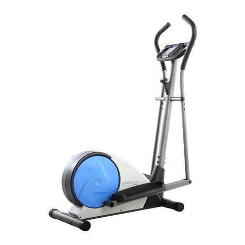
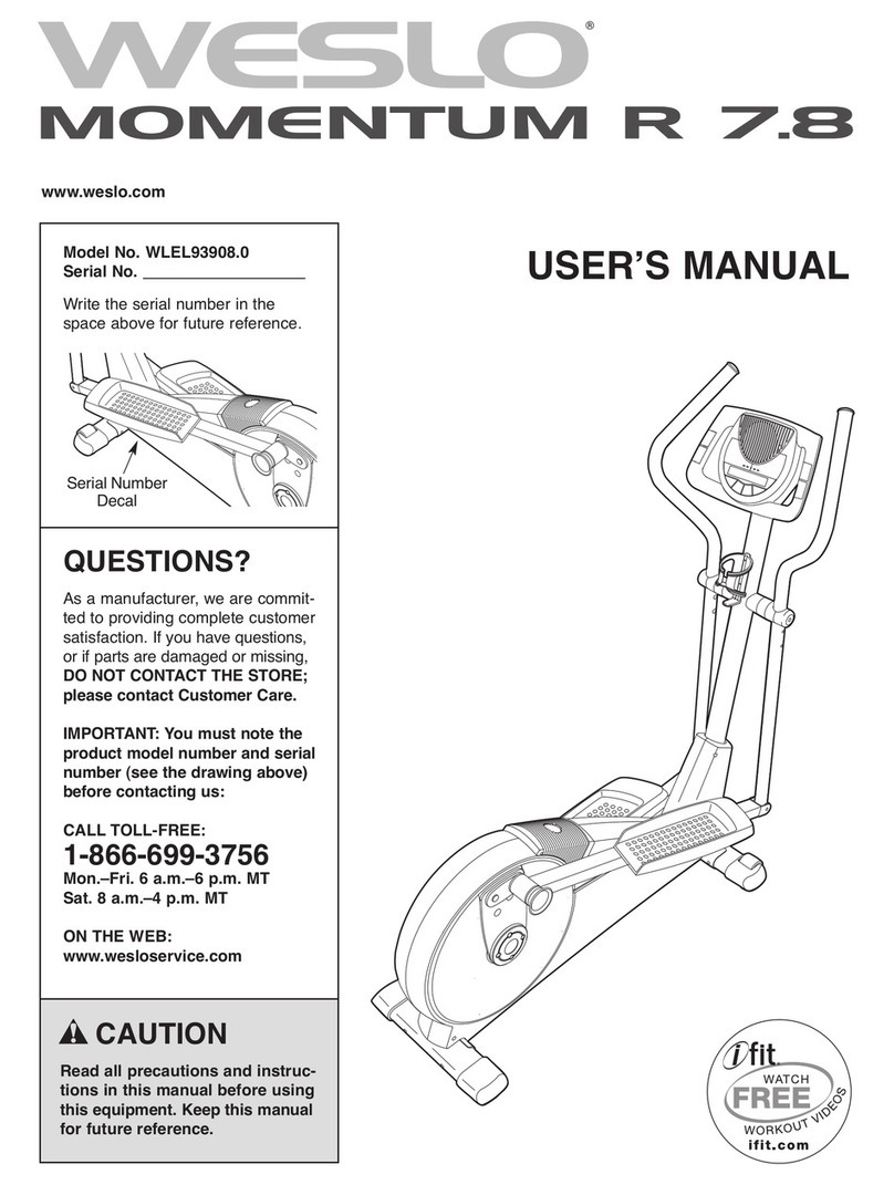
Weslo Eclipse 2 WLEMEL45071 User manual

Weslo

Weslo Eclipse 2 WLEMEL45071 User manual

Weslo Momentum 850 Elliptical User manual

Weslo

Weslo Momentum 850 Elliptical User manual

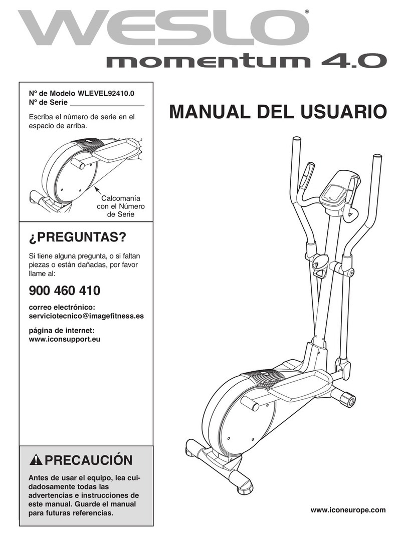
Weslo Momentum 4.0 Elliptical User manual

Weslo

Weslo Momentum 4.0 Elliptical User manual

Weslo Momentum G 3.8 Elliptical User manual

Weslo

Weslo Momentum G 3.8 Elliptical User manual

Weslo WLEL19021 User manual

Weslo

Weslo WLEL19021 User manual

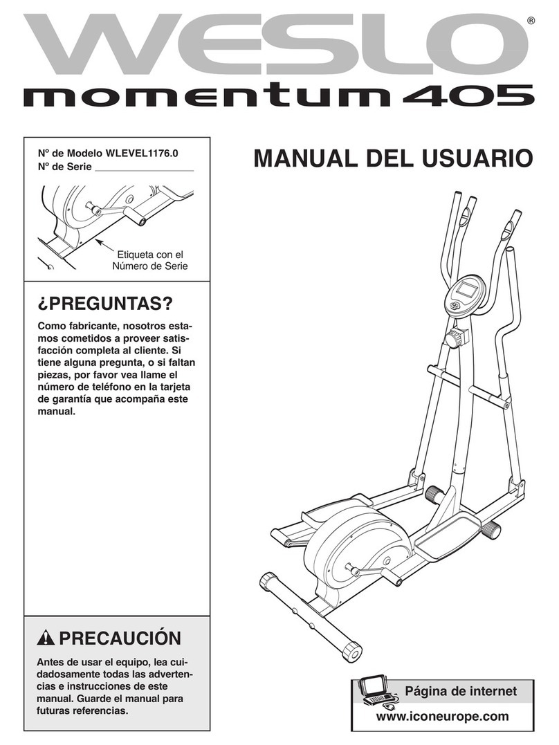
Weslo Momentum 405 Elliptical User manual

Weslo

Weslo Momentum 405 Elliptical User manual

Weslo Momentum 605 Elliptical User manual

Weslo

Weslo Momentum 605 Elliptical User manual

Weslo Momentum5.9 Elliptical User manual

Weslo

Weslo Momentum5.9 Elliptical User manual

Weslo Momentum 220x Elliptical User manual

Weslo

Weslo Momentum 220x Elliptical User manual

Weslo Elliptical Glider 2.0 User manual

Weslo

Weslo Elliptical Glider 2.0 User manual

Weslo ALTA User manual

Weslo

Weslo ALTA User manual

Weslo WLEX31212.0 User manual

Weslo

Weslo WLEX31212.0 User manual

Weslo Elliptical Glider 2.0 Operating and maintenance manual

Weslo

Weslo Elliptical Glider 2.0 Operating and maintenance manual

Weslo Momentum 4.8 Elliptical User manual

Weslo

Weslo Momentum 4.8 Elliptical User manual

Weslo Momentum 4.0 Elliptical Quick start guide

Weslo

Weslo Momentum 4.0 Elliptical Quick start guide

Weslo Momentum 220X WLEL2006.0 User manual

Weslo

Weslo Momentum 220X WLEL2006.0 User manual

Weslo Momentum 850 Elliptical User manual

Weslo

Weslo Momentum 850 Elliptical User manual

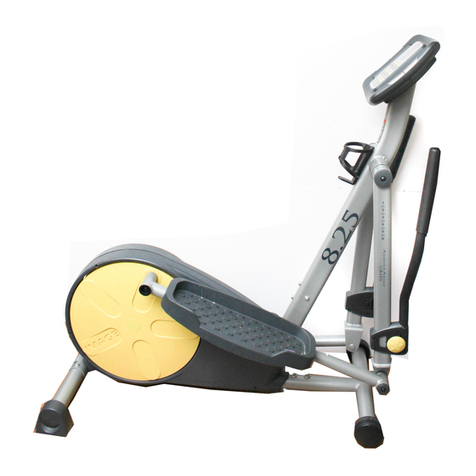
Weslo 8.25 Elliptical User manual

Weslo

Weslo 8.25 Elliptical User manual

Weslo Body Shop 2 User manual

Weslo

Weslo Body Shop 2 User manual

Weslo Momentum 410 Elliptical System manual

Weslo

Weslo Momentum 410 Elliptical System manual

Weslo Elliptical Glider 2.0 User guide

Weslo

Weslo Elliptical Glider 2.0 User guide

Weslo Momentum 4.0 Elliptical Operating and maintenance manual
Weslo

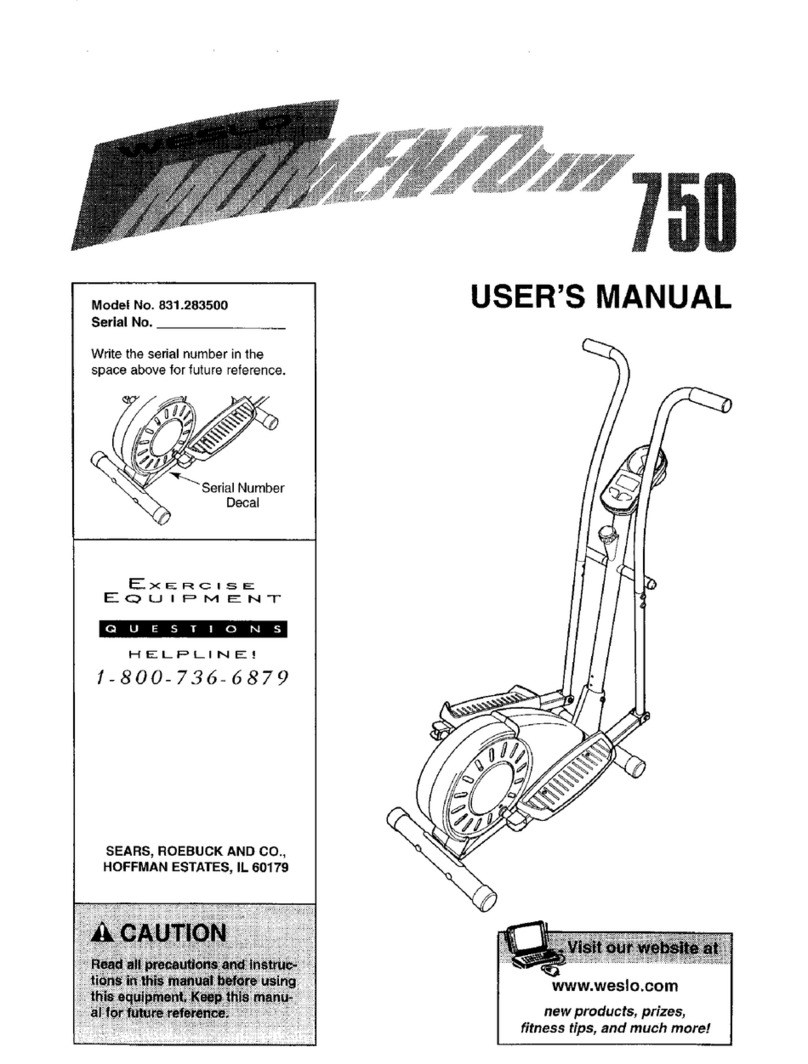
Weslo Momentum 4.0 Elliptical Operating and maintenance manual
Weslo Momentum 4.0 Elliptical User manual

Weslo

Weslo Momentum 4.0 Elliptical User manual

Weslo Momentum 615 Elliptical User manual

Weslo

Weslo Momentum 615 Elliptical User manual

Popular Elliptical Trainer manuals by other brands
NordicTrack AudioStrider 990 PRO NTEL09811.2 user manual

NordicTrack

NordicTrack AudioStrider 990 PRO NTEL09811.2 user manual

Progear Fitness Air elliptical pro 1307 owner's manual

Progear Fitness

Progear Fitness Air elliptical pro 1307 owner's manual

Torque Fitness XPLLP owner's manual

Torque Fitness

Torque Fitness XPLLP owner's manual

Octane Fitness PRO3700C Operation manual

Octane Fitness

Octane Fitness PRO3700C Operation manual

Xterra FS5.8e owner's manual

Xterra

Xterra FS5.8e owner's manual

Bodyguard E-40 user manual

Bodyguard

Bodyguard E-40 user manual

Vision Fitness X6600iNetTV Assembly guide

Vision Fitness

Vision Fitness X6600iNetTV Assembly guide

NordicTrack E 7.2 Elliptical null

NordicTrack

NordicTrack E 7.2 Elliptical null

NordicTrack E4.1 Elliptical null

NordicTrack

NordicTrack E4.1 Elliptical null

NordicTrack E4.1 Elliptical null

NordicTrack

NordicTrack E4.1 Elliptical null

Pro-Form 690 Hr Elliptical null

Pro-Form

Pro-Form 690 Hr Elliptical null

Pro-Form 800 Hr Heart Rate Control Elliptical null

Pro-Form

Pro-Form 800 Hr Heart Rate Control Elliptical null

Bonn Germany Concept 2.2 user manual

Bonn Germany

Bonn Germany Concept 2.2 user manual

Precor Resolute RSL 620 Assembly guide
Precor

Precor Resolute RSL 620 Assembly guide

NordicTrack E 9.2 Elliptical HASZNALATI UTASITAS

NordicTrack

NordicTrack E 9.2 Elliptical HASZNALATI UTASITAS

Sears FREE SPIRIT C249 30737 0 owner's manual
Sears

Sears FREE SPIRIT C249 30737 0 owner's manual

True FS-64 Assembly manual

True

True FS-64 Assembly manual

Sport-thieme ST 310 manual

Sport-thieme

Sport-thieme ST 310 manual

manuals.online logo
manuals.online logoBrands
  • About & Mission
  • Contact us
  • Privacy Policy
  • Terms and Conditions

Copyright 2025 Manuals.Online. All Rights Reserved.

USER’S
MANUAL
CAUTION
Read all precautions and
instructions in this manual
before usin this equipment.
Keep this manual for future
reference.
Model No. WLEMEL09910
Serial No.
Serial
Number
Decal
QUESTIONS?
As a manufacturer, we are
committed to providin com-
plete customer satisfaction. If
you have questions, or if there
are missin or dama ed parts,
please call:
Or write:
ICON Health & Fitness, Ltd.
Unit 4,
Revie Road Industrial Estate
Revie Road
Beeston
Leeds, LS118JG
UK
email: [email protected]
www.weslo.com
Visit our website at
08457 089 009
2
TABLE OF CONTENTS
IMPORTANT PRECAUTIONS . . . . . . . . . . . . . . . . . . . . . . . . . . . . . . . . . . . . . . . . . . . . . . . . . . . . . . . . . . . . .3
BEFORE YOU BEGIN . . . . . . . . . . . . . . . . . . . . . . . . . . . . . . . . . . . . . . . . . . . . . . . . . . . . . . . . . . . . . . . . . . .4
PART IDENTIFICATION CHART . . . . . . . . . . . . . . . . . . . . . . . . . . . . . . . . . . . . . . . . . . . . . . . . . . . . . . . . . . .
ASSEMBLY . . . . . . . . . . . . . . . . . . . . . . . . . . . . . . . . . . . . . . . . . . . . . . . . . . . . . . . . . . . . . . . . . . . . . . . . . . .6
HOW TO USE THE ELLIPTICAL GLIDER . . . . . . . . . . . . . . . . . . . . . . . . . . . . . . . . . . . . . . . . . . . . . . . . . . . .9
MAINTENANCE . . . . . . . . . . . . . . . . . . . . . . . . . . . . . . . . . . . . . . . . . . . . . . . . . . . . . . . . . . . . . . . . . . . . . . .11
CONDITIONING GUIDELINES . . . . . . . . . . . . . . . . . . . . . . . . . . . . . . . . . . . . . . . . . . . . . . . . . . . . . . . . . . . .12
PART LIST . . . . . . . . . . . . . . . . . . . . . . . . . . . . . . . . . . . . . . . . . . . . . . . . . . . . . . . . . . . . . . . . . . . . . . . . . . .14
EXPLODED DRAWING . . . . . . . . . . . . . . . . . . . . . . . . . . . . . . . . . . . . . . . . . . . . . . . . . . . . . . . . . . . . . . . . .1
HOW TO ORDER REPLACEMENT PARTS . . . . . . . . . . . . . . . . . . . . . . . . . . . . . . . . . . . . . . . . . . .Back Cover
WESLO is a registered trademark of ICON Health & Fitness, Inc.
3
1. Read all instructions in this manual before
usin the elliptical lider.
2. Use the elliptical lider only as described in
this manual.
3. It is the responsibility of the owner to
ensure that all users of the elliptical lider
are adequately informed of all precautions.
4. Place the elliptical lider on a level surface,
with a mat beneath it to protect the floor or
carpet. Keep the elliptical lider indoors,
away from moisture and dust.
5. Inspect and ti hten all parts re ularly.
Replace any worn parts immediately.
6. Keep children under the a e of 12 and pets
away from the elliptical lider at all times.
7. The elliptical lider should not be used by
persons wei hin more than 114 k (250
lbs.).
8. Wear appropriate clothin when usin the
elliptical lider. Always wear athletic shoes
for foot protection.
9. When mountin and dismountin the ellipti-
cal lider, always hold the handlebars and
step onto and off the pedal that is in the
lowest position.
10. Each time you stop exercisin on the
elliptical lider, allow the pedals to come to
a complete stop before dismountin .
11. Always keep your back strai ht when usin
the elliptical lider. Do not arch your back.
12. If you feel pain or dizziness at any time
whilst exercisin , stop immediately and
be in coolin down.
13. The elliptical lider is intended for in-home
use only. Do not use the elliptical lider in a
commercial, rental, or institutional settin .
14. The decal shown below has been placed on
the exercise cycle. If the decal is missin , or
if it is not le ible, please call our Customer
Service Department at 08457 089 009 to
order a free replacement decal. Apply the
decal in the location shown.
IMPORTANT PRECAUTIONS
WARNING: To reduce the risk of serious injury, read the followin important precau-
tions before usin the WESLO®2.0 elliptical lider.
WARNING: Before be innin this or any exercise pro ram, consult your physician.
This is especially important for persons over the a e of 35 or persons with pre-existin health
problems. Read all instructions before usin . ICON assumes no responsibility for personal injury
or property dama e sustained by or throu h the use of this product.
• Misuse of this product may result in serious
injury.
• Read user’s manual and follow all warnin s
and operatin instructions prior to use.
• Do not allow children on or around machine.
• Replace label if dama ed, ille ible, or removed.
WARNING
!
4
BEFORE YOU BEGIN
Congratulations for selecting the WESLO®2.0 elliptical
glider. The 2.0 is an incredibly smooth exerciser that
moves your feet in a natural elliptical path, minimising
the impact on your knees and ankles. And the unique
2.0 features adjustable resistance, upper-body handle-
bars, and a multi-mode exercise monitor to help you
get the most from your exercise. Welcome to a whole
new world of natural, elliptical-motion exercise from
WESLO.
For your benefit, read this manual carefully before
you use the elliptical lider. If you have additional
questions, please call our Customer Service Depart-
ment at 08457 089 009. To help us assist you, please
mention the product model number and serial number
when calling. The model number is WLEMEL09910.
The serial number can be found on a decal attached
to the elliptical glider (see the front cover of this man-
ual for the location of the decal).
Before reading further, please look at the drawing
below and familiarise yourself with the parts that are
labelled.
Resistance Knob
FRONT
BACK
LEFT SIDE
Pedal Arm
Side Shield
Pedal
Remote Holder
Upright
Water Bottle Holder
(Bottle not included)
Handlebar
5
PART IDENTIFICATION CHART
Use the chart below to identify the small parts used in
assembly. The number in parenthesis below each part
refers to the key number of the part, from the PART
LIST on page 14. The number after the dash indicates
the quantity needed for assembly. Note: Some parts
may have been pre-attached for shippin . If a part
is not in the parts ba , check to see if it has been
pre-attached.
M8 x 19mm
Button Screw (10)–2
M8 x 63mm Carriage Bolt (49)–4
M x 30mm
Button Bolt ( 1)–4
M8 x 38mm Button Bolt ( 3)–2
M4 x 12mm
Button Screw ( 7)–4
M Nylon
Locknut ( 2)–4
M8 Nylon
Locknut ( 0)–8
1/2” Nylon
Locknut (3 )–2
M8 x 60mm Bolt ( 6)–2
Pivot Washer ( 4)–2 Pedal Washer (32)–2
M4 x 19mm Flange
Screw ( )–6
Note: Extra parts may be included.
6
ASSEMBLY
Assembly requires two people. Place all parts of the elliptical glider in a cleared area and remove the packing
materials. Do not dispose of the packing materials until assembly is completed.
Assembly requires that you have two adjustable spanner , a rubber mallet , and
the included allen wrench .
1. Identify the Front Stabiliser (18), which is the nar-
rowest Stabiliser. If there are no Stabiliser Endcaps
(20) on the Front Stabiliser, push one onto each end.
Attach the Front Stabiliser (18) to the front of the
Frame (1) with two M8 x 63mm Carriage Bolts (49)
and two M8 Nylon Locknuts ( 0).
2. If there are no Stabiliser Endcaps (20) on the Rear
Stabiliser (19), push one onto each end.
Attach the Rear Stabiliser (19) to the Frame (1) with
two M8 x 63mm Carriage Bolts (49) and two M8
Nylon Locknuts ( 0).
3. Whilst a second person holds the Upright (2) near
the Frame (1), connect the Extension Wire (47) to
the Reed Switch Wire (41).
Insert the Upright (2) into the Frame (1), being care-
ful to avoid damaging the wires. Make sure that the
Frame Bushings (3) are inserted fully into the
Frame. Adjust the Upright (2) so that a bolt can be
inserted through the centre hole in each side.
Secure the Upright with two M8 x 38mm Button
Bolts ( 3) and two M8 Nylon Locknuts ( 0).
20
2
3
1
18
49
20
0
19
20
0
49
2
3
3
0
41
47 0
3
1
1
0
0
1
20
7
. Identify the Left Pivot Arm (6), which is marked with a
sticker that has an “L” on it. Make sure that there are
two Pivot Bushings (9) in the Left Pivot Arm. Slide the
Left Pivot Arm onto the Pivot Axle (11), making sure
that it is oriented as shown. Put a Pivot Washer ( 4)
onto an M8 x 19mm Button Screw (10) and tighten
the Button Screw into the Pivot Axle.
6. Insert a Handlebar (12) into the Right Pivot Arm (7).
Slide the Foam Grip (13) up to expose the mounting
holes. Secure the Handlebar with two M x 30mm
Button Bolts ( 1) and two M Nylon Locknuts ( 2).
Slide the Foam Grip down over the Button Bolts and
Nylon Locknuts.
Attach the other Handlebar to the Left Pivot Arm (6) in
the same manner.
9
10
4
9
6
13
1
2
6
7
6
11
12
4. Make sure that the two Upright Bushings (8) are
inserted into the Upright (2). Apply a thin film of the
included grease to the length of the Pivot Axle (11).
Insert the Pivot Axle into the Upright Bushings and
the Upright.
Identify the Right Pivot Arm (7), which is marked with
a sticker that has an “R” on it. Make sure that there
are two Pivot Bushings (9) in the Right Pivot Arm.
Slide the Right Pivot Arm onto the Pivot Axle (11),
making sure that it is oriented as shown. Put a Pivot
Washer ( 4) onto an M8 x 19mm Button Screw (10)
and tighten the Button Screw into the Pivot Axle.
4
9
8
8
2
7
11
Grease
10
9
4
8
10. Make sure that all parts of the elliptical lider are properly ti htened. Place a mat under the elliptical glider
to protect the floor or carpet from damage.
9
7
47
Console
Wire
28
29
2
9. The Console ( ) requires two 1, V “AA” batteries (not
included). Alkaline batteries are recommended.
To install batteries, look under the Console and locate
the battery compartment. Insert two batteries into the
battery compartment; make sure that the batteries
are turned so the ne ative ends (marked “–”) are
touchin the sprin s in the battery compartment.
Connect the console wire to the Extension Wire (47).
Attach the Console ( ) to the Upright (2) with four M4
x 12mm Button Screws ( 7).
Push the Resistance Knob (28) firmly onto the
Resistance Cable (29).
8. Identify the Left Pedal Arm (14), which is marked with
a sticker that has an “L” on it. Make sure that there are
two Pedal Arm Bushing (33) in the Left Pedal Arm.
Apply a thin film of the included grease to a Pedal
Axle (34). Insert the Pedal Axle into the Left Pedal
Arm, and slide a Pedal Washer (32) onto the Pedal
Axle. Firmly tighten the Pedal Axle into the Crank (30).
Tighten a 1/2” Nylon Locknut (3 ) onto the end of the
Pedal Axle protruding from the Crank.
Make sure that there are two Small Pivot Bushing
(42) in the Left Pivot Arm (6). Apply a thin film of the
included grease to an M8 x 60mm Bolt ( 6). Attach
the Left Pivot Arm to the Left Pedal Arm (14) with the
Bolt and an M8 Nylon Locknut ( 0).
Attach the Right Pedal Arm (not shown) in the same
manner.
8
7. Identify the Left Pedal Arm (14), which is marked with
a sticker that has an “L” on it. Next, identify the Left
Pedal (16), which has an “L” molded into the bottom.
Attach the Left Pedal to the Left Pedal Arm with three
M4 x 19mm Flange Screws ( ).
Attach the Right Pedal to the Right Pedal Arm (not
shown) in the same manner.
7
34
33
33
3
42
42
0
6
14
14
16
32 30
6
Batteries
Grease
9
HOW TO USE THE ELLIPTICAL GLIDER
HOW TO EXERCISE ON THE ELLIPTICAL GLIDER
To mount the elliptical glider, firmly hold the handle-
bars and carefully step onto the pedal that is in the
lowest position. Next, step onto the other pedal. Push
the pedals until they begin to move with a continuous
motion. Note: The pedals can turn in either direc-
tion. It is recommended that you turn the pedals
in the direction shown below; however, to ive
variety to your exercise, you may choose to turn
the pedals in the opposite direction.
To dismount the elliptical glider, allow the pedals to
come to a complete stop. CAUTION: The elliptical
lider does not have a free wheel; the pedals will
continue to move until the flywheel stops. When
the pedals are stationary, step off the highest pedal
first. Then, step off the lowest pedal.
HOW TO ADJUST THE RESISTANCE OF THE
PEDALS
As you exercise,
you can adjust the
resistance of the
pedals with the
resistance knob.
To increase the
resistance, turn
the knob clock-
wise; to decrease
the resistance,
turn the knob
counterclockwise.
Pedal
Resistance
Knob
10
DESCRIPTION OF THE CONSOLE
The innovative console features five modes that dis-
play instant exercise feedback. The modes are
described below:
Speed—This mode shows your exercise pace, in rev-
olutions per minute.
Revolutions—This mode shows the total number of rev-
olutions you have pedalled.
Calories—This mode shows the approximate number
of calories you have burned.
Time—This mode will show the elapsed time. Note:
When you stop exercising, the time will flash when it
is displayed.
Scan—This mode displays the other four modes, for
five seconds each, in a repeating cycle.
BATTERY INSTALLATION
Before the console can be operated, two 1, V “AA”
batteries must be installed. If you have not installed
batteries, see assembly step 9 on page 8. Note: It will
be necessary to remove the console to install batteries.
HOW TO OPERATE THE CONSOLE
1. To turn on the power, press the on/reset button or
simply begin pedalling. When the power is turned
on, the entire display will appear for two seconds.
The console will then be ready for operation.
2. Select one of the five modes:
Scan mode—
When the
power is
turned on, the
scan mode will
automatically
be selected.
One mode
indicator will show that the scan mode is selected,
and a flashing mode indicator will show which
mode is currently displayed. Note: If a different
mode is selected, you can select the scan mode
again by repeatedly pressing the display button.
Speed, time,
revolutions, or
calories
mode—To
select one of
these modes
for continuous
display,
repeatedly press the display button. The mode indi-
cators will show which mode is selected. (Make
sure that the scan mode is not selected.)
3. To reset the display, press the on/reset button.
4. To turn off the power, simply wait for about four
minutes. Note: The console has an “auto-off”
feature. If the pedals are not moved and the
console buttons are not pressed for four min-
utes, the power will turn off automatically in
order to conserve the batteries.
Mode Indicators
Mode Indicator