Westin 58-41045 User manual

1
Westin Automotive Products, Inc.
320 W. Covina Blvd
San Dimas, Ca. 91773
Thank you for choosing Westin products
for additional installation assistance please call
Customer Service (800) 793-7846
www.westinautomotive.com
P.N.: 75-5841045-RevA ECO #: W18-153 DATE: 06/25/19
INSTALLATION INSTRUCTIONS
ITEM QUANTITY DESCRIPTION TOOLS NEEDED
1 1 CENTER SECTION 10MM SOCKET
2 1 DRIVER SIDE POD 17MM SOCKET
3 1 PASSENGER SIDE POD 19MM SOCKET
4 1 DRIVER MOUNTING BRACKET ALLEN WRENCH
5 1 PASSENGER MOUNTING BRACKET CUTTING TOOL
6 1 DRIVER SUPPORT BRACKET RULER
7 1 PASSENGER SUPPORT BRACKET MARKER
8 2 LED LIGHT BRACKET TAPE
9 12 M6 BUTTON HEAD BOLT (BLACK ZINC) PRYING TOOL
10 24 M6 FLAT WASHER (BLACK ZINC) RATCHET
11 12 M6 SERRATED FLANGE NUT (BLACK ZINC) TORQUE WRENCH
12 12 M6 LOCK WASHER (BLACK ZINC)
13 4 M10 BUTTON HEAD BOLT (BLACK ZINC)
14 4 M10 SPLIT LOCK WASHER (BLACK ZINC)
15 8 M10 FLAT WASHER (BLACK ZINC)
16 4 M10 HEX NUT (BLACK ZINC)
17 14 M12 FLAT WASHER (YELLOW ZINC)
18 4 M10 SERRATED FLANGE NUT (YELLOW ZINC)
19 8 M10 FLAT WASHER (YELLOW ZINC)
20 4 M10 HEX HEAD BOLT (YELLOW ZINC)
21 4 M12 SERRATED FLANGE NUT (YELLOW ZINC)
22 4 M12 HEX BOLT (YELLOW ZINC)
23 4 M12 LOCK WASHER (YELLOW ZINC)
24 1 DRIVER MESH POD COVER
25 1 PASSENGER MESH POD COVER
ANTI-SEIZE LUBRICANT MUST BE USED ON ALL STAINLESS STEEL FASTENERS TO PREVENT THREAD DAMAGE AND GALLING
CONTENT
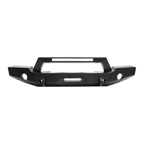
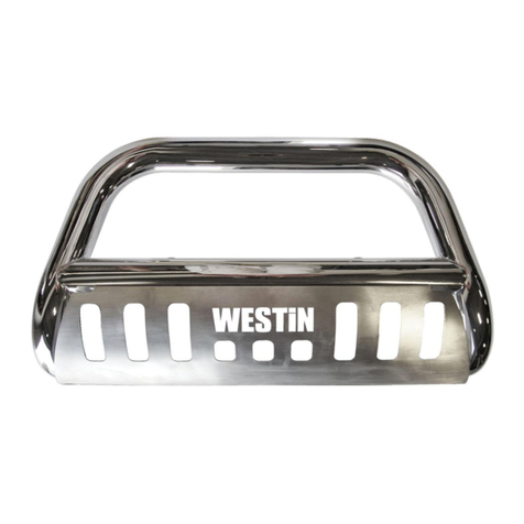
PRO MOD BUMPER
APPLICATION:
2016-2019 Toyota Tacoma
PART NUMBER:
58-41045
PROCEDURE
1. Remove contents from box, verify if all parts listed are present and free from damage.
Carefully read and understand all instructions before attempting installation.
Failure to identify damage before installation could lead to a rejection of any claim.

2
Westin Automotive Products, Inc.
320 W. Covina Blvd
San Dimas, Ca. 91773
Thank you for choosing Westin products
for additional installation assistance please call
Customer Service (800) 793-7846
www.westinautomotive.com
P.N.: 75-5841045-RevA ECO #: W18-153 DATE: 06/25/19
2. To remove front bumper, first remove the grill, fender flares and valance. To remove grill, remove two screws and push pins
fastening it to the radiator area. See Figure 1 and 2. Once all fasteners have been removed, firmly pull radiator from top
towards the front of the vehicle.
Figure 1
Figure 2
ITEM 2 (Driver) ITEM 3 (Passenger) ITEM 24 (Driver)
ITEM 25 (Passenger) ITEM 1
ITEM 8 ITEM 4 ITEM 6

3
Westin Automotive Products, Inc.
320 W. Covina Blvd
San Dimas, Ca. 91773
Thank you for choosing Westin products
for additional installation assistance please call
Customer Service (800) 793-7846
www.westinautomotive.com
P.N.: 75-5841045-RevA ECO #: W18-153 DATE: 06/25/19
3. Next, remove fender flares by removing screws around the wheel well area; once all visible fasteners have been re-
moved, firmly and carefully pull to unclip push pins. Save fender flares for later. They will be installed back and
trimmed. See Figure 3
Figure 3 Figure 4
4. Remove valance by removing all fasteners holding it
to the bottom of the bumper and wheel well liners.
See Figures 4 and 5.
Figure 5
5. Remove all push pins fastening the bumper to the
vehicle around the grille area and around head
lights. Also, make sure to disconnect all wires and
fog lights attached to the bumper.
Figure 6

4
Westin Automotive Products, Inc.
320 W. Covina Blvd
San Dimas, Ca. 91773
Thank you for choosing Westin products
for additional installation assistance please call
Customer Service (800) 793-7846
www.westinautomotive.com
P.N.: 75-5841045-RevA ECO #: W18-153 DATE: 06/25/19
Figure 7
6. To remove bumper, it is recommended to seek assistance from a second person. Begin by pushing back wheel well
plastic to expose a red push pin holding the bumper to a black plastic piece bolted to the metallic fender. See Figure
7 and 8.
Figure 8
PUSH
7. Push red pin to allow black plastic piece to be sepa-
rated from metallic fender See Figure 8, then us-
ing a pry tool, insert under tab to separate from
bumper. Carefully separate the three tabs on each
side of the truck. See Figure 9. When you com-
pletely detach one side, have someone hold the
bumper for you to avoid damage on the other side.
It is not necessary to unbolt black plastic piece
from the fender. The bumper will be installed
back again later after trimming.
Figure 9

5
Westin Automotive Products, Inc.
320 W. Covina Blvd
San Dimas, Ca. 91773
Thank you for choosing Westin products
for additional installation assistance please call
Customer Service (800) 793-7846
www.westinautomotive.com
P.N.: 75-5841045-RevA ECO #: W18-153 DATE: 06/25/19
9. Lay the OEM bumper assembly on a flat table. You will need a ruler, tape, and a marker.
a. Starting at the driver side of the bumper. Measure from the top corner down 1.75”. Mark a dash at that point. See Figure
11-12
8. Next, remove the aluminum bar attached to the frame of the vehicle using a 14MM socket or wrench. Remove by pulling
firmly both sides at the same time. Save these nuts, they will be reused. See Figure 10.
Figure 10
TRIMMING INSTRUCTIONS
Measure here
Fig. 11 Fig. 12
1.75”

6
Westin Automotive Products, Inc.
320 W. Covina Blvd
San Dimas, Ca. 91773
Thank you for choosing Westin products
for additional installation assistance please call
Customer Service (800) 793-7846
www.westinautomotive.com
P.N.: 75-5841045-RevA ECO #: W18-153 DATE: 06/25/19
B. Align a ruler with the edge of the bumper as shown in Fig. 13. Then, extend a line collinear to the edge of the bumper until it intersects
the next edge on the bumper; mark a point on that intersection. Shown as a star on Fig. 14.
Then, measure 1” down that star following the edge of the bumper and mark a point. Shown as a triangle.
c. Using the ruler as a straightedge, connect the triangle to the dot as seen in Figure 15. Then extend the line towards the fog
lamp pocket all the way to the end. This will be the trim line. But first, complete the next step to double check your line is
correct.
d. Measure from the intersection of your trim line and the edge of the fog lamp pocket to the upper edge of that bumper face.
Verify that this measurement is 3.5”. If it is not, then check your measurements and redraw the lines. If the measurement is
correct, then you are ready to cut. See Figure 15
e. Cut across the plastic as straight as possible, carefully using a very sharp knife or cutting tool.
f. Repeat the process on the passenger side.
g. Re-install the OEM bumper assembly and fender flares after trimming is complete. See Figure 16 for example of
trimmed bumper.
Fig. 13 Fig. 14
Fig. 15
Passenger Side Shown
3.5”
1”

7
Westin Automotive Products, Inc.
320 W. Covina Blvd
San Dimas, Ca. 91773
Thank you for choosing Westin products
for additional installation assistance please call
Customer Service (800) 793-7846
www.westinautomotive.com
P.N.: 75-5841045-RevA ECO #: W18-153 DATE: 06/25/19
h. Using the re–installed bumper as reference, lay a strip of tape parallel with the cut line on to the fender flare. Cut along
this line. Repeat on passenger side. See Figure 17.
i. Trimming Procedure complete.
Fig. 16
Fig. 17

8
Westin Automotive Products, Inc.
320 W. Covina Blvd
San Dimas, Ca. 91773
Thank you for choosing Westin products
for additional installation assistance please call
Customer Service (800) 793-7846
www.westinautomotive.com
P.N.: 75-5841045-RevA ECO #: W18-153 DATE: 06/25/19
10. 9. Install items 4-5 to frame studs exposed on step 8. Install OEM nuts removed on step 8 but do not tighten. See Figure
18.
Figure 18
11. Loosely install the center section and side pods to the main brackets using the supplied M12 Hardware. See Figure 19.
22
23
17 17 21
1
4
2
Fig. 19

9
Westin Automotive Products, Inc.
320 W. Covina Blvd
San Dimas, Ca. 91773
Thank you for choosing Westin products
for additional installation assistance please call
Customer Service (800) 793-7846
www.westinautomotive.com
P.N.: 75-5841045-RevA ECO #: W18-153 DATE: 06/25/19
12. Loosely assemble the side support straps (6-7) on to the bumper using the supplied M10 hardware. See Figure 20.
6
4
2
Fig. 20
13. Attach the Mesh Side Covers (24-25) to the Bumper using the supplied M6 Hardware. See Figures 21 & 22.
Driver Side Shown
12
10
9
Fig. 21
24
2

10
Westin Automotive Products, Inc.
320 W. Covina Blvd
San Dimas, Ca. 91773
Thank you for choosing Westin products
for additional installation assistance please call
Customer Service (800) 793-7846
www.westinautomotive.com
P.N.: 75-5841045-RevA ECO #: W18-153 DATE: 06/25/19
14. Align bumper as desired and torque all hardware as specified: M6 to 7 ft-lbs, M10 to 38 ft-lbs, M12 to 60 ft-lbs.
Fig. 22
11
2

11
Westin Automotive Products, Inc.
320 W. Covina Blvd
San Dimas, Ca. 91773
Thank you for choosing Westin products
for additional installation assistance please call
Customer Service (800) 793-7846
www.westinautomotive.com
P.N.: 75-5841045-RevA ECO #: W18-153 DATE: 06/25/19
CARE INSTRUCTIONS
REGULAR WAXING IS RECOMMENDED. DO NOT USE ANY TYPE OF POLISH OR WAX THAT MAY CONTAIN ABRASIVES.
STAINLESS STEEL PRODUCTS CAN BE CLEANED WITH MILD SOAP AND WATER. STAINLESS STEEL POLISH SHOULD BE USED TO POLISH SMALL SCRATCHES.
GLOSS BLACK FINISHES SHOULD BE CLEANED WITH MILD SOAP AND WATER.
INSTALL COMPLETE

12
Westin Automotive Products, Inc.
320 W. Covina Blvd
San Dimas, Ca. 91773
Thank you for choosing Westin products
for additional installation assistance please call
Customer Service (800) 793-7846
www.westinautomotive.com
P.N.: 75-5841045-RevA ECO #: W18-153 DATE: 06/25/19
Failure to follow these instructions could lead to death, personal injury, and / or property damage.
WARNING
Failure to follow these instructions could lead to death, personal injury, and / or property damage.
FASTENERS:
All Westin supplied fasteners must be utilized and installed in accordance with the installation in-
structions and apply torque to the specifications as defined. DOUBLE CHECK ALL FASTENERS
BEFORE INITIAL USE, AND PERIODICALLY IN THE FUTURE TO ENSURE PROPER FUNCTION
AND SAFETY.
DRILLING:
Most Westin products do not require drilling for installation. If drilling is defined as required, use
caution when drilling a vehicle. FAILURE TO REVIEW AN AREA TO BE DRILLED MAY RESULT IN
PERSONAL INJURY AND/OR INJURY TO OTHERS AS WELL AS VEHICLE DAMAGE.
EYE PROTECTION:
ALWAYS WEAR SAFETY GLASSES OR GOGGLES DURING THE INSTALLATION PROCESS TO
AVOID PERSONAL INJURY.
MAXIMUM TOWING/CARRYING CAPACITY: (if applicable)
The Westin Receiver Hitches will have a visible tow rating label affixed directly on the product.
User should never exceed the vehicle manufacturers maximum tow and weight rating regardless
of the capacity of the hitch. FAILURE TO FOLLOW THESE GUIDELINES WILL VOID THE WESTIN
WARRANTY AND MAY RESULT IN PERSONAL INJURY AND/OR INJURY TO OTHERS AS WELL
AS VEHICLE DAMAGE.
FOR CALIFORNIA RESIDENTS ONLY-PROP 65 WARNING:
Some products may contain chemicals such as DEHP, which can cause cancer, birth defects or
other reproductive harm. For more info go to www.p65warnings.ca.gov
Table of contents
Other Westin Automobile Accessories manuals

Westin
Westin 27-1165 User manual

Westin
Westin PRO TRAXX 6 User manual

Westin
Westin 59-8202 User manual

Westin
Westin 25-3360 User manual

Westin
Westin PRO TRAXX 4 Series User manual

Westin
Westin E Series User manual

Westin
Westin Pro Series User manual

Westin
Westin 32-2360 User manual

Westin
Westin SPORTSMAN 40-1125 User manual

Westin
Westin 40-2055 User manual

Westin
Westin 30-0020 User manual
Westin
Westin 57-6025 User manual

Westin
Westin 22-1815 User manual

Westin
Westin 21-2310 User manual

Westin
Westin HDX RUNNING BOARDS User manual

Westin
Westin 57-9003 User manual

Westin
Westin 27-1255 User manual
Westin
Westin 46-24025 User manual

Westin
Westin 22-1555 User manual

Westin
Westin 21-1680 User manual