WHILL C2 User manual

WHILL Model C2/Ci2
Operating Guide
This Operating Guide is intended to provide instructions on basic usage of the device.
To operate the device safely, please ensure to carefully read this guide before use.
It is recommended to keep this guide on hand at all time for your reference.

Avoid rail road crossings and take a safer route whenever possible.
If you must pass a rail road crossing, ensure you understand how to manually
release the brakes (p4) and ask a caretaker to accompany you.
Do not drive the device in areas with soft surfaces such as sand, mud, snow or
frozen paths. There is a risk that accidents may occur.
1
1. Major precautions for use
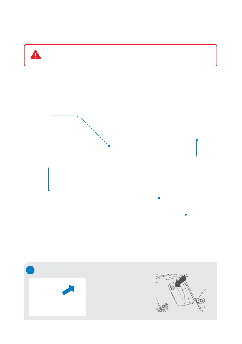
When crossing railroad crossings or
tram tracks, approach and cross
perpendicular to the tracks.
Ensure the device does not get stuck
in the groove of the tracks.
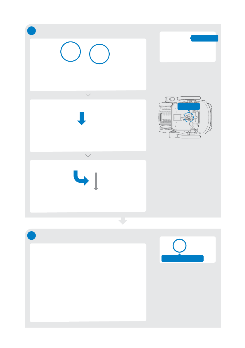
Do not drive at
places where the
device may lean
significantly.
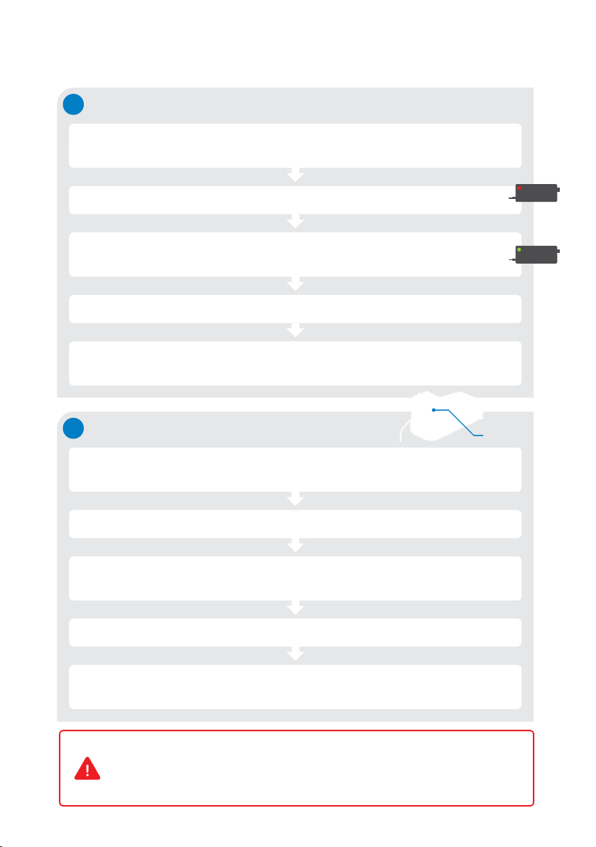
The WHILL Model C2/Ci2 is a mobility vehicle. Persons who find it difficult to use a
powered wheelchair should refrain from using the device.
·
The maximum load weight for this device is 300 lb (approx. 136 kg). It includes both
the occupant and any luggage. Ensure the the load weight does not exceed the
maximum during use.
·
Turn off the device power when getting in and out of the device.
·
Keep your feet on the foot rest while driving to avoid feet or clothing getting
caught in moving components.
·
Avoid traffic and narrow space, and follow the traffic rules to drive safely.
Dress appropriately for driving.
·
There is a risk that clothing such as long scarves, loose pants, skirts and rain
coats may be caught in tires or other parts of the device, resulting in injury.
·
When wearing gloves, be careful to avoid getting them caught in the device,
such as in the control components.
Drive carefully in the following areas.

2
2. Basic operations
Get in the
device Confirm the device power is off before getting into the device.
1
Set speed Adjust the speed setting from 1 to 4 by using speed select buttons.
3
Turn on
the power Press the power button and confirm the display turns on.
2
Move and
turn around Move the joystick slowly in the desired direction.
4
Stop Release the joystick.
5
Turn off
the power Press the power button and confirm the display turns off.
6
Get out of
the device Confirm the display is off, and then get out of the device.
7
Battery charge level
Battery level is displayed
from 0% to 100%.
Speed select buttons
+ : Increase the
maximum speed.
- : Decrease the
maximum speed.
Power button
Control pad
Sound button
Let people know you
are there.
Ensure to turn off the device power when getting in and out of the device.

Basic operations
2.Driving tips
1
How to stop
Release the joystick to stop. Releasing the joystick automatically applies the
brakes and stops the device even on an uphill or downhill slope.
2
How to hold the joystick
Place fingers on the joystick.
3
How to move the joystick
Adjusting the speed
The device speed can be
controlled by the tilting
degree of movement of
the joystick.
In the beginning, ensure
to operate the joystick
gently and drive slowly.
Climbing over a step
When climbing over a
step, approach at a right
angle to the step.
Tilting a little = slow
Stop when the front
wheels bump into
the step.
Slow down after
the front wheels have
climbed over the step.
Do the same for
the rear wheels to get
the device over the step.
Tilting more = fast
3

Turn off the device power.
Push down both of the two
brake release levers below
the seat.
Raise both brake release
levers to re-engage the
brakes afterwards.
4
3. Releasing the brakes
Certain situations may require control of the device without powering on and using
the joystick—known as freewheel mode. This can be accomplished using the two
red brake release levers.
4. Using the smart key
The smart key can be used to lock and unlock
the device.
LED Lock button
Unlock button
Levers to engage or
release the brakes
Do not release the brakes on a slope. Be sure to release the brakes only when on a
flat surface and in emergencies after turning off the power. After moving the
device manually with the brakes released, be sure to raise the two brake release
levers to re-engage the brakes.
Press the smart key lock button.
The icon indicating the locked status
will appear on the controller’s display
and make a locking sound. When
attempting to turn on the device when
the device is locked, the icon indicating
the locked status will appear on the
display. The device cannot be turned on.
Press the smart key unlock button.
The smart key LED will illuminate, and
the icon indicating unlocked status will
appear on the display and make a
unlocking sound. The device will be
unlocked.
Locked Unlocked
Sold separately. Equipped with standard items depending on the areas/countries.

This device can be disassembled into the following five components.
※Remove the battery before disassembling.
5. Disassembly procedure
When assembling or disassembling the device, grab only the handles and parts
as described in the instructions, and do not hold the device by any other areas.
1
Press the battery’s
lock release button.
Grasp the handle and
pull to remove the
battery.
Removing the battery
5
Seat
assembly
Front drive base
Battery
Rear drive base
Storage basket
Lock release
button

3
Remove items from storage basket, then lift the storage basket straight up by holding
its handles and remove it from the front drive base.
Removing the storage basket
4Disconnecting the front drive base
Raise the base release handle. Grab the handle near the center of the
front drive base and disconnect Bar B
on one end of the front drive base from
the hook of the rear drive base.
2
※Lift the seat assembly slowly so that it does not damage other parts.
※When placing the seat assembly on the floor, place it with the cushion facing up.
Removing the seat assembly
Pull up the seat release lever toward you. Lift up the seat assembly by the arm rests.
6
Base release handle
Seat release lever
Bar B
Handle
When lifting the seat assembly, the magnetism of the magnetic connectors
located at the connection between the seat assembly and rear drive base
may have an adverse effect on electrical medical devices. Persons who
have an implanted pacemaker, implanted defibrillator, or other electrical
medical devices in their bodies, must leave a minimum of 8 inches (20 cm)
between themselves and the magnetic connectors.
Base release
handle
* When disassembling, support the rear drive base with your hand
to prevent it from falling over.

6. Assembly procedure
7
2Installing the storage basket Align the hooks on the
bottom of the storage
basket with the frame of
the front drive base, then
push the storage basket
straight down. Push the
flat part at the bottom of
the basket until it clicks.
1Assembling the front drive base and rear drive base
Grab the handle near the
center of the front drive
base while tilting up the
rear drive base. Then
align Bar B with the hook
on the rear drive base.
Slowly tilt the rear drive
base forward and connect
it to the front drive base.
The base release handle
of the rear drive base
latches onto Bar A of the
front drive base. A click
will be heard when the
two parts are connected
properly.
Click
Handle
Bar A
Bar B
If the device does not start properly even though a charged battery is inserted
to the device and the device is turned on, remove the battery, then re-insert the
battery after 10 seconds.

8
3Installing the seat assembly
Remove the seat cushion,
grab the arm rests, and
lift the seat assembly.
Use the view hole to align
and position the seat
assembly onto the seat
post.
Push down the seat
release lever into the
vertical position, and
attach the cushion back to
a seat base.
Seat cushion
4Installing the battery
Ensure that the battery
lock release button is not
pressed. Grab the battery
handle and insert the
battery into the battery
compartment.
If experiencing difficulty,
push the battery with
more force.
Lock release button
View hole

7. Charging the battery
1Charging with the battery installed in the device
Move the device close to the outlet and turn off the device power.
Connect the charger and AC connector cord.
Charging is completed when the charger indicator turns solid green.
Remove the battery charging port cap and connect the DC connector to the battery
charging port. The charger indicator begins flashing green and charging starts.
Disconnect the DC connector from the battery, then disconnect the plug from the
power outlet. Close the cap of the battery charging port.
2Charging with the battery removed
Connect the charger and AC connector cord. Plug the charger into the power outlet.
Charging is completed when the charger indicator and battery LED turns solid green.
Remove the cap of the battery charging port and connect the DC connector to it.
The charger indicator begins flashing green, and charging starts.
Disconnect the DC connector from the battery, and then
the plug from the power outlet.
Check the device power is off and press the battery lock release button.
Grasp the handle and pull to remove the battery.
9
·
Do not touch the battery and charger during charging to prevent burns.
·
Ensure charging the battery indoors.
·
The battery and charger are for the WHILL Model C2 only.
·
Only use the designated battery and charger for the device.
Battery
charging
port
Plug the charger into the power outlet. The charger indicator illuminates red.

10
8. Troubleshooting
In the event of certain issues with the device, an error code will appear on the display.
If an unlisted error is displayed or the issue persists even though a problem was handled in
line with troubleshooting, contact your distributor or customer support.
The maximum
speed recovers.
The icon shown
on the right
appears.
The maximum
speed
decreases.
The charger was connected
while the power was on, or the
device was turned on while
being connected to the charger.
The battery charge level is
low.
The battery temperature
dropped significantly.
The battery temperature
rose above 0°C (32°F).
The smart key battery level
is low.
The device may be on a steep
uphill slope.
Disconnect the charger from
the battery.
Recharge the battery.
Store the battery in room
temperature or at least in an
ambient temperature of
above 0°C (32°F) until the
battery temperature rises
above 0°C (32°F).
Replace the smart key
battery.
The device may be on a slope
unsafe to operate. Move
slowly to a place where the
slope is gentle while
checking your safety. Once
warning sound is made, it
will not be made again for
about 2 minutes.
The icon shown
on the right
appears.
Operation of control pad
attempted while arm is
rotated upward.
The joystick was not in the
neutral position when the
power was turned on.
The brake levers are
disengaged.
Lower the arm and turn the
power on again.
Power back on without
touching the joystick.
Lock the brakes and turn the
power on again.
Behavior of
the device Error code Cause Resolution
The icon shown
on the right
appears.
When the device does not turn on, check the battery level and if it is inserted fully
into the compartment. If the device does not start properly, remove the battery,
then re-insert the battery after 10 seconds and turn on the device after 5 seconds.

32-10037-0 Rev 1
How to pair your smartphone app
App allows users to check total mileage, distance traveled, battery level,
full charge cycles and to use the remote control function. Users can also
lock and unlock the unit.
*The two codes are printed on the paper slip placed in the indent of the seat of the device.
Note: Depending on your region and smartphone type, the app may not be offered, or some
functions may not be available.
Model C2
1. You need to install the app beforehand. To install, go to the
App Store and search for “WHILL”. Click the blue WHILL logo
icon for the WHILL Model C2/Ci2 app.
(The grey logo icon is for WHILL Model C.)
2. To pair your device, launch the WHILL Model C2 app and
enter the following codes* on the screen.
11-digit alphanumeric code
password
Other manuals for C2
1
This manual suits for next models
1
Table of contents
Other WHILL Wheelchair manuals